2007 MITSUBISHI LANCER EVOLUTION low oil pressure
[x] Cancel search: low oil pressurePage 96 of 1449

HOW TO READ THE WIRING DIAGRAMS -Abbreviation SymbolsA-10
ABBREVIATION SYMBOLS
The abbreviation symbols used in wiring diagrams are defined below.
1. Abbreviation symbols used for system name
Abbreviation
symbolsMeaningAbbreviation
symbolsMeaning
A/CAir conditionerEGRExhaust gas recirculation
ABSAnti-skid braking systemETACSElectronic time alarm control system
ACDActive center differentialSRSSupplemental restraint system
AY CActive yaw control
2. Abbreviation symbols used for combination meters
Abbreviation
symbolsMeaningAbbreviation
symbolsMeaning
ABSAnti-skid braking system warning lampSNOWActive center differential mode indicator
lamp
BEAMHigh beam indicator lampSPEEDSpeedmeter
BRAKEBrake warning lampSRSSupplemental restraint system warning
lamp
CHECK
ENGINECheck engine warning lampTARMACActive center differential mode indicator
lamp
CHGCharging warning lampT/GAEngine coolant temperature gauge
DOORDoor-ajar warning lampTACHOTachometer
F/GAFuel gaugeTAILTail, position and licence plate indicator
lamp
FRONT FOGFront fog indicator lamp
lamp
FUELLow fuel warning lampTRIPTripmeter
GRAVELActive center differential mode indicator
lampTURN (LH)Turn signal indicator lamp (LH)
ODOOdometerTURN (RH)Trun signal indicator lamp (RH)
OILOil pressure warning lampWATER
SPRAY
Intercooler water spray indicator lamp
REAR FOGRear fog indicator lamp
SPRAY
3. Abbreviation symbols used for switched and relay
Name of switches and
relaysAbbreviation
symbolsOperation
Blower switchLOBlower operates at low speed
MLBlower operates at medium low speed
MHBlower operates at medium high speed
HIBlower operates at high speed
Page 109 of 1449

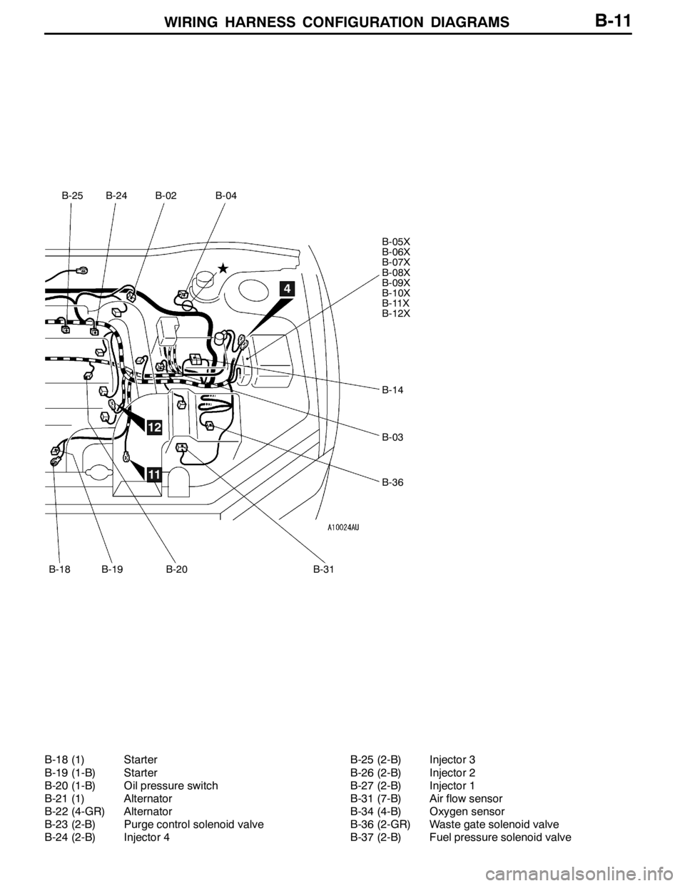
WIRING HARNESS CONFIGURATION DIAGRAMS
B-25
B-18
B-24B-02B-04
B-05X
B-06X
B-07X
B-08X
B-09X
B-10X
B-11X
B-12X
B-14
B-03
B-36
B-19B-20B-31
4
11
12
B-11
B-18 (1) Starter
B-19 (1-B) Starter
B-20 (1-B) Oil pressure switch
B-21 (1) Alternator
B-22 (4-GR) Alternator
B-23 (2-B) Purge control solenoid valve
B-24 (2-B) Injector 4B-25 (2-B) Injector 3
B-26 (2-B) Injector 2
B-27 (2-B) Injector 1
B-31 (7-B) Air flow sensor
B-34 (4-B) Oxygen sensor
B-36 (2-GR) Waste gate solenoid valve
B-37 (2-B) Fuel pressure solenoid valve
Page 113 of 1449

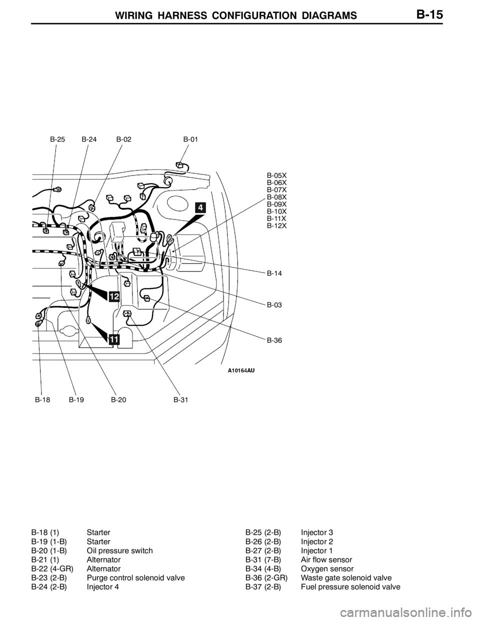
WIRING HARNESS CONFIGURATION DIAGRAMS
B-25
B-18
B-24B-02B-01
B-05X
B-06X
B-07X
B-08X
B-09X
B-10X
B-11X
B-12X
B-14
B-03
B-36
B-19B-20B-31
4
11
12
B-15
B-18 (1) Starter
B-19 (1-B) Starter
B-20 (1-B) Oil pressure switch
B-21 (1) Alternator
B-22 (4-GR) Alternator
B-23 (2-B) Purge control solenoid valve
B-24 (2-B) Injector 4B-25 (2-B) Injector 3
B-26 (2-B) Injector 2
B-27 (2-B) Injector 1
B-31 (7-B) Air flow sensor
B-34 (4-B) Oxygen sensor
B-36 (2-GR) Waste gate solenoid valve
B-37 (2-B) Fuel pressure solenoid valve
Page 253 of 1449

CIRCUIT DIAGRAMSB-155
FUEL WARNING LAMP (See P.B-156.)
OIL PRESSURE WARNING LAMP (See P.B-157.)
BRAKE WARNING LAMP (See P.B-157.)
OPERATION
DWhen the ignition switch is at the “ON” position,
the fuel gauge unit resistance is small when
the fuel level is high, and the fuel gauge unit
resistance is large when the fuel level is low.
When this resistance rises above a specified
value, the fuel warning lamp illuminates to notify
the driver that the fuel level is low.
DWhen the lubrication system fails after engine
starting, resulting in the oil pressure failing to
build up, the oil pressure switch turns on
causing the oil pressure warning lamp to
illuminate.
DWhen the brake fluid level goes down below
a predetermined level with the ignition switch
in the “ON” position, the brake fluid level switch
is activated or the parking brake switch is turned
on, causing the brake warning lamp to
illuminate.TROUBLESHOOTING HINTS
1. No warning lamps illuminate.
DCheck multi-purpose fuse No.(2).
2. Some warning lamps do not illuminate.
DCheck lamp valve.
DCheck the switches and the gauge unit.
Page 358 of 1449

INDEX - In order of connector No.C-2
Wiring diagram
page Circuit diagram page Parts name Connector
No.
AA-45Condenser fan motorB-177,183B-7,9
A-46Condenser fan motorB-177,183B-7,9
A-47A/C compressorB-178,184B-7,9
A-48Power steering oil pressure switchB-90,98B-7,9
BB-01Windshield wiper motorB-186,190B-10,14
B-02Throttle position sensorB-89,97,215,223,231,241B-10,14
B-03Vehicle speed sensorB-92,100,150,154,197B-10,14
B-04Brake fluid level switchB-157B-10,14
B-05XEngine speed detection connectorB-73,82,83,90,98B-10,14
B-06XNo connectionB-73B-10,14
B-07XNo connectionB-73B-10,14
B-08XNo connectionB-73B-10,14
B-09XIgnition coil relay
connection
B-10XNo connectionB-73B-10,14
B-11XEngine control relayB-73,86,94,252,254B-10,14
B-12XA/C compressor relayB-73,178,184B-10,14
B-14Control wiring harness and battery
wiring harness combinationB-79,84,91,99,157B-10,14
B-18StarterB-79B-11,15
B-19StarterB-79B-11,15
B-20Oil pressure switchB-157B-11,15
B-21AlternatorB-84B-11,15
B-22AlternatorB-84B-11,15
B-23Purge control solenoid valveB-91,99B-11,15
B-24Injector 4B-89,97B-11,15
B-25Injector 3B-89,97B-11,15
B-26Injector 2B-89,97B-11,15
B-27Injector 1B-89,97B-11,15
B-31Air flow sensorB-90,98B-11,15
B-34Oxygen sensorB-88,96B-11,15
B-36Waste gate solenoid valveB-91,99B-11,15
B-37Fuel pressure solenoid valveB-90,98B-11,15
Page 397 of 1449

GENERAL -Precautions Before ServiceGENERAL -Precautions Before Service00-19
SERVICING THE ELECTRICAL SYSTEM
Before replacing a component related to the electrical system
and before undertaking any repair procedures involving the
electrical system, be sure to first disconnect the negative
( - ) cable from the battery in order to avoid damage caused
by short-circuiting.
Caution
Before connecting or disconnecting the negative ( - ) cable,
be sure to turn off the ignition switch and the lighting
switch.
(If this is not done, there is the possibility of
semiconductor parts being damaged.)
APPLICATION OF ANTI-CORROSION AGENTS
AND UNDERCOATS
If oil or grease gets onto the oxygen sensor, it will cause
a drop in the performance of the sensor.
Cover the oxygen sensor with a protective cover when applying
anti-corrosion agents and undercoats.
PRE-INSPECTION CONDITION
“Pre-inspection condition” refers to the condition that the
vehicle must be in before proper engine inspection can be
carried out. If you see the words “Set the vehicle to the
pre-inspection condition”. in this manual, it means to set the
vehicle to the following condition.
DEngine coolant temperature: 80 to 90_C
DLamps, electric cooling fan and all accessories: OFF
DM/T: Neutral
DA/T: P range
VEHICLE WASHING
If high-pressure car-washing equipment or steam car-washing
equipment is used to wash the vehicle, be sure to note the
following information in order to avoid damage to plastic
components, etc.
DSpray nozzle distance: Approx. 40 cm or more
DSpray pressure: 3,900 kPa or less
DSpray temperature: 82_C or less
DTime of concentrated spray to one point: within 30 sec.
Approx.
40 cm
Page 416 of 1449

ENGINE -On-vehicle ServiceENGINE -On-vehicle Service11A-10
Standard value: 5_BTDC±3_
5. Run the engine at idle for 2 minutes.
6. Check the idle speed. Select item No. 22 and take a
reading of the idle speed.
Curb idle speed: 850±100 r/min
NOTE
The idle speed is controlled automatically by the idle speed
control (ISC) system.
7. If the idle speed is outside the standard value, check
the MPI components by referring to GROUP 13A -
Troubleshooting.
8. Remove the timing light.
9. Turn the ignition switch to the “LOCK” (OFF) position
and then remove the MUT-II.
IDLE MIXTURE CHECK
1. Before inspection, set the vehicle to the pre-inspection
condition.
2. Turn the ignition switch to the “LOCK” (OFF) position,
and then connect the MUT-IIto the diagnosis connector.
3. Set the timing light.
4. Check that the basic ignition timing is within the standard
value.
Standard value: 5_BTDC±3_
5. Run the engine at 2,500 r/min for 2 minutes.
6. Set the CO, HC tester.
7. Check the CO contents and the HC contents at idle.
Standard value
CO contents: 0.1% or less
HC contents: 100 ppm or less
8. If there is a deviation from the standard value, check the
following items:
DDiagnosis output
DClosed-loop control (When the closed-loop control
is normal, the output signal of the oxygen sensor
changes between 0 - 400 mV and 600 - 1,000 mV
at idle.)
DFuel pressure
DInjector
DIgnition coil, spark plug cable, spark plug
DEvaporative emission control system
DCompression pressure
NOTE
Replace the three way catalyst when the CO and HC
contents are not within the standard value, even though
the result of the inspection is normal on all items.
9. Remove the timing light.
MUT-II
Page 417 of 1449

ENGINE -On-vehicle ServiceENGINE -On-vehicle ServiceENGINE -On-vehicle Service11A-11
10. Turn the ignition switch to the “LOCK” (OFF) position
and then remove the MUT-II.
COMPRESSION PRESSURE CHECK
1. Before inspection, check that the engine oil, starter and
battery are normal. In addition, set the vehicle to the
pre-inspection condition.
2. Remove the ignition coils and spark plug cables.
3. Remove all of the spark plugs.
4. Disconnect the crank angle sensor connector.
NOTE
Doing this will prevent the engine-ECU from carrying out
ignition and fuel injection.
5. Cover the spark plug hole with a shop towel etc., and
after the engine has been cranked, check that no foreign
material is adhering to the shop towel.
Caution
(1) Keep away from the spark plug hole when
cranking.
(2) If compression is measured with water, oil, fuel,
etc., that has come from cracks inside the cylinder,
these materials will become heated and will gush
out from the spark plug hole, which is dangerous.
6. Set compression gauge to one of the spark plug holes.
7. Crank the engine with the throttle valve fully open and
measure the compression pressure.
Standard value (at engine speed of 250 r/min):
1,128 kPa
Limit (at engine speed of 250 r/min):
Min. 951 kPa
8. Measure the compression pressure for all the cylinders,
and check that the pressure differences of the cylinders are
below the limit.
Limit: Max. 98 kPa
9. If there is a cylinder with compression or a compression
difference that is outside the limit, pour a small amount
of engine oil through the spark plug hole, and repeat
the operations in steps 7 and 8.
(1) If the compression increases after oil is added, the
cause of the malfunction is a worn or damaged piston
ring and/or cylinder inner surface.
(2) If the compression does not rise after oil is added,
the cause is a burnt or defective valve seat, or pressure
is leaking from the gasket.
10. Connect the crank angle sensor connector.
11. Install the spark plugs.
Crank angle sensor
connector