2007 MITSUBISHI LANCER EVOLUTION transmission fluid
[x] Cancel search: transmission fluidPage 108 of 1449

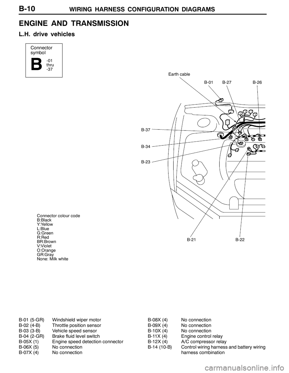
WIRING HARNESS CONFIGURATION DIAGRAMS
Connector
symbol
-01
thru
-37
B
B-37
B-34
B-23
B-01B-27B-26
Earth cable
B-21B-22
Connector colour code
B:Black
Y:Yellow
L:Blue
G:Green
R:Red
BR:Brown
V:Violet
O:Orange
GR:Gray
None: Milk white
B-10
ENGINE AND TRANSMISSION
L.H. drive vehicles
B-01 (5-GR) Windshield wiper motor
B-02 (4-B) Throttle position sensor
B-03 (3-B) Vehicle speed sensor
B-04 (2-GR) Brake fluid level switch
B-05X (1) Engine speed detection connector
B-06X (5) No connection
B-07X (4) No connectionB-08X (4) No connection
B-09X (4) No connection
B-10X (4) No connection
B-11X (4) Engine control relay
B-12X (4) A/C compressor relay
B-14 (10-B) Control wiring harness and battery wiring
harness combination
Page 112 of 1449

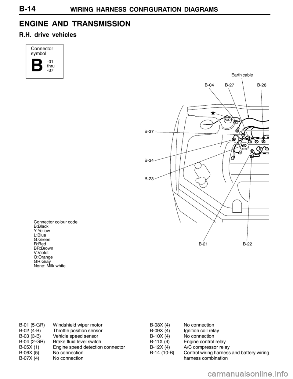
WIRING HARNESS CONFIGURATION DIAGRAMS
Connector
symbol
-01
thru
-37
B
Earth cable
B-27B-26B-04
B-22B-21
B-37
B-34
B-23
Connector colour code
B:Black
Y:Yellow
L:Blue
G:Green
R:Red
BR:Brown
V:Violet
O:Orange
GR:Gray
None: Milk white
B-14
ENGINE AND TRANSMISSION
R.H. drive vehicles
B-01 (5-GR) Windshield wiper motor
B-02 (4-B) Throttle position sensor
B-03 (3-B) Vehicle speed sensor
B-04 (2-GR) Brake fluid level switch
B-05X (1) Engine speed detection connector
B-06X (5) No connection
B-07X (4) No connectionB-08X (4) No connection
B-09X (4) Ignition coil relay
B-10X (4) No connection
B-11X (4) Engine control relay
B-12X (4) A/C compressor relay
B-14 (10-B) Control wiring harness and battery wiring
harness combination
Page 382 of 1449

GENERAL -How to Use This Manual00-4
EXPLANATION OF MANUAL CONTENTS
Indicates procedures to be performed
before the work in that section is started,
and procedures to be performed after
the work in that section is finished.
Indicates (by symbols) where lubrica-
tion is necessary.
Maintenance and Servicing Procedures
The numbers provided within the diagram indi-
cate the sequence for maintenance and servic-
ing procedures.
DRemoval steps:
The part designation number corresponds
to the number in the illustration to indicate
removal steps.
DDisassembly steps:
The part designation number corresponds
to the number in the illustration to indicate
disassembly steps.DInstallation steps:
Specified in case installation is impossible
in reverse order of removal steps. Omitted
if installation is possible in reverse order of
removal steps.
DReassembly steps:
Specified in case reassembly is impossible
in reverse order of disassembly steps.
Omitted if reassembly is possible in reverse
order of disassembly steps.
Classifications of Major Maintenance/Service Points
When there are major points relative to maintenance and servicing procedures
(such as essential maintenance and service points, maintenance and service stan-
dard values, information regarding the use of special tools, etc.), these are ar-
ranged together as major maintenance and service points and explained in detail.
AA": Indicates that there are essential points for removal or disassembly.
"AA: Indicates that there are essential points for installation or reassembly.
Symbols for Lubrication, Sealants and Adhesives
Information concerning the locations for lubrica-
tion and for application of sealants and adhe-
sives is provided, by using symbols, in the dia-
gram of component parts or on the page follow-
ing the component parts page, and explained.: Grease
(multipurpose grease unless there is
a brand or type specified)
: Sealant or adhesive
: Brake fluid or automatic transmission fluid
: Engine oil, gear oil or air conditioner
compressor oil
: Adhesive tape or butyl rubber tape
Component Diagram
A diagram of the component parts is
provided near the front of each section
in order to give a reader a better under-
standing of the installed condition of
component parts.
Page 636 of 1449

MPI -Troubleshooting13A-104
Item
No.Reference
page Inspection
procedure
No. Normal condition Inspection contents Inspection
item
25Barometric
pressure
Ignition switch: ONAltitude: 0 m101 kPaCode No.
P0105
13A-15
pressure
sensor
Altitude: 0 m95 kPa
P0105
Altitude: 0 m88 kPa
Altitude: 0 m81 kPa
27Power
steering
fluidEngine: Idle operationSteering wheel
stationaryOFFCode No.
P055113A-46
fluid
pressure
switchSteering wheel turningON
28A/C switchEngine: Idle operation
(When A/C switch isA/C switch: OFFOFFProcedure
No. 2613A-92
(WhenA/Cswitchis
ON, A/C compressor
should be operating.)A/C switch: ONON
No.26
34Air flow
sensorEngine: After
warm-upIdle operationONCode No.
P010013A-13
sensor
reset
signal
warm up
3,000 r/minOFF
P0100
37Volumetric
efficiency
DEngine coolant
temperature:
Idle operation15 - 35%--
efficiencytemperature:
85 - 95_C
DLightningand
2,500 r/min15 - 35%
DLightning and
accessories:
OFFExcessive
accellerationAccording to ac-
celeration, volu-
metric efficiency
is increased.
41Injectors*1Engine: CrankingWhen engine coolant
temperature is 0_C
(injection is carried out
for all cylinders simulta-
neously)25 - 37 ms--
When engine coolant
temperature is 20_C15 - 22 ms
When engine coolant
temperature is 80_C4.2 - 6.3 ms
Injectors*2DEngine coolant
temperature:
80–95_C
Engine: Idle operation1.5 - 2.7 ms--
80–95_C
DLamps, electric
cooling fan and
allaccessories:
2,500 r/min1.2 - 2.4 ms
allaccessories:
OFF
DTransmission:
Neutral
When engine is sud-
denly racedIncreases
Page 810 of 1449

22A-2
MANUAL
TRANSMISSION
CONTENTS
GENERAL 3.................................
Outline of Changes 3...........................
GENERAL INFORMATION 3..................
SERVICE SPECIFICATION 3..................
LUBRICANTS 3..............................
SPECIAL TOOLS 4...........................
TROUBLESHOOTING
ON-VEHICLE SERVICE 40....................
Transmission Oil Check 40......................
Transmission Oil Replacement 40................
Transfer Oil Check 40..........................
Transfer Oil Replacement 40....................
Fluid Check
Bleeding
Hydraulic Pressure Check
Wheel Speed Sensor Output Voltage
Measurement
TRANSMISSION CONTROL* 46...............
TRANSFER ASSEMBLY 49...................
TRANSMISSION ASSEMBLY 52...............
4WD-ECU
SENSOR, SWITCH AND RELAY
AYC> 56.....................................
HYDRAULIC UNIT Refer to GROUP27B.......
WARNING REGARDING SERVICING OF SUPPLEMENTAL RESTRAINT SYSTEM (SRS) EQUIPPED VEHICLES
WARNING!
(1) Improper service or maintenance of any component of the SRS, or any SRS-related component, can lead to personal
injury or death to service personnel (from inadvertent firing of the air bag) or to driver and passenger (from rendering
the SRS inoperative).
(2) Service or maintenance of any SRS component or SRS-related component must be performed only at an authorized
MITSUBISHI dealer.
(3) MITSUBISHI dealer personnel must thoroughly review this manual, and especially its GROUP 52B - Supplemental
Restraint System (SRS) before beginning any service or maintenance of any component of the SRS or any SRS-related
component.
NOTE
The SRS includes the following components: SRS-ECU, SRS warning lamp, air bag module, clock spring, and interconnecting
wiring. Other SRS-related components (that may have to be removed/installed in connection with SRS service or maintenance) are
indicated in the table of contents by an asterisk (*).
Page 811 of 1449

MANUAL TRANSMISSION -General/General Information/
Service Specification/Lubricants22A-3
GENERAL
OUTLINE OF CHANGE
With the addition of the EVOLUTION-VII, the W5M51 transmission service adjustment procedure has
been set as follows.
GENERAL INFORMATION
ItemsSpecifications
GradeRS, RS IIRS, RS II (With super cross gear)
Transmission modelW5M51
Engine model4G63-DOHC-T/C
Type5-speed, floor-shift
Gear ratio1st2.7852.785
2nd1.9501.950
3rd1.4071.444
4th1.0311.096
5th0.7200.825
Reverse3.4163.416
Final reduction ratio
(Differential gear ratio)4.5294.529
Front limited-slip differential
(Helical-gear type)Not providedProvided
TransferReduction ratio3.3073.307
Limited-slipdifferentialVCU or hydraulic multi plate
clutch (ACD)VCU or hydraulic multi plate
clutch (ACD)
SERVICE SPECIFICATION
ItemStandard value
Hydraulic unit generation oil pressureMPa1.0 - 1.6
LUBRICANTS
ItemSpecified lubricantQuantity L
Transmission oilGear oil SAE 75W-90 or 75W-85W conforming to API GL-42.8
Transfer
oilVehicles without ACD or ve-
hicles without ACD and AYCMITSUBISHI Genuine Gear Oil Part No.8149630 EX,
CASTROL HYPOY LS (GL-5, SAE 90), SHELL-LSD
(GL 5SAE80W90)orequivalent
0.55
Vehicles with ACD or vehicles
with ACD and AYC(GL-5, SAE 80W - 90) or equivalent0.6
FluidPiping between ACD and
hydraulic unitDIA QUEEN ATF SP III0.9
Pipes between ACD and hy-
draulic unit and between AYC
and hydraulic unit1.0
Page 838 of 1449

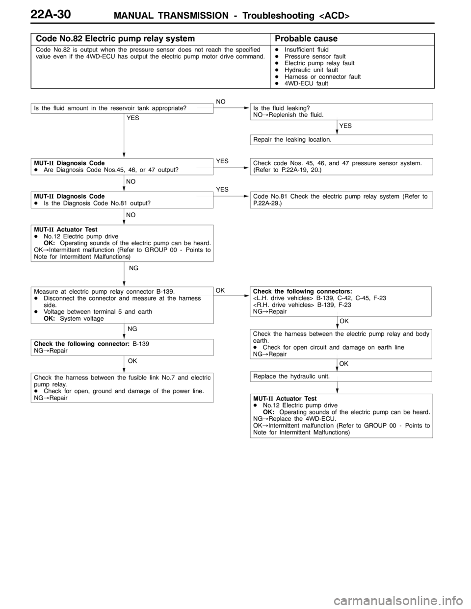
MANUAL TRANSMISSION - Troubleshooting
Code No.82 Electric pump relay systemProbable cause
Code No.82 is output when the pressure sensor does not reach the specified
value even if the 4WD-ECU has output the electric pump motor drive command.DInsufficient fluid
DPressure sensor fault
DElectric pump relay fault
DHydraulic unit fault
DHarness or connector fault
D4WD-ECU fault
OK
OK
NG
NG
MUT-IIActuator Test
DNo.12 Electric pump drive
OK:Operating sounds of the electric pump can be heard.
OK→Intermittent malfunction (Refer to GROUP 00 - Points to
Note for Intermittent Malfunctions)
Check the following connectors:
NG→Repair
OK
Check the following connector:B-139
NG→Repair
Check the harness between the fusible link No.7 and electric
pump relay.
DCheck for open, ground and damage of the power line.
NG→Repair
Measure at electric pump relay connector B-139.
DDisconnect the connector and measure at the harness
side.
DVoltage between terminal 5 and earth
OK:System voltage
MUT-IIActuator Test
DNo.12 Electric pump drive
OK:Operating sounds of the electric pump can be heard.
NG→Replace the 4WD-ECU.
OK→Intermittent malfunction (Refer to GROUP 00 - Points to
Note for Intermittent Malfunctions)
YES
NOIs the fluid amount in the reservoir tank appropriate?
YES
Is the fluid leaking?
NO→Replenish the fluid.
Repair the leaking location.
YES
NO
MUT-IIDiagnosis Code
DAre Diagnosis Code Nos.45, 46, or 47 output?Check code Nos. 45, 46, and 47 pressure sensor system.
(Refer to P.22A-19, 20.)
YESCode No.81 Check the electric pump relay system (Refer to
P.22A-29.)
NO
MUT-IIDiagnosis Code
DIs the Diagnosis Code No.81 output?
OK
Check the harness between the electric pump relay and body
earth.
DCheck for open circuit and damage on earth line
NG→Repair
Replace the hydraulic unit.
Page 842 of 1449

MANUAL TRANSMISSION - Troubleshooting
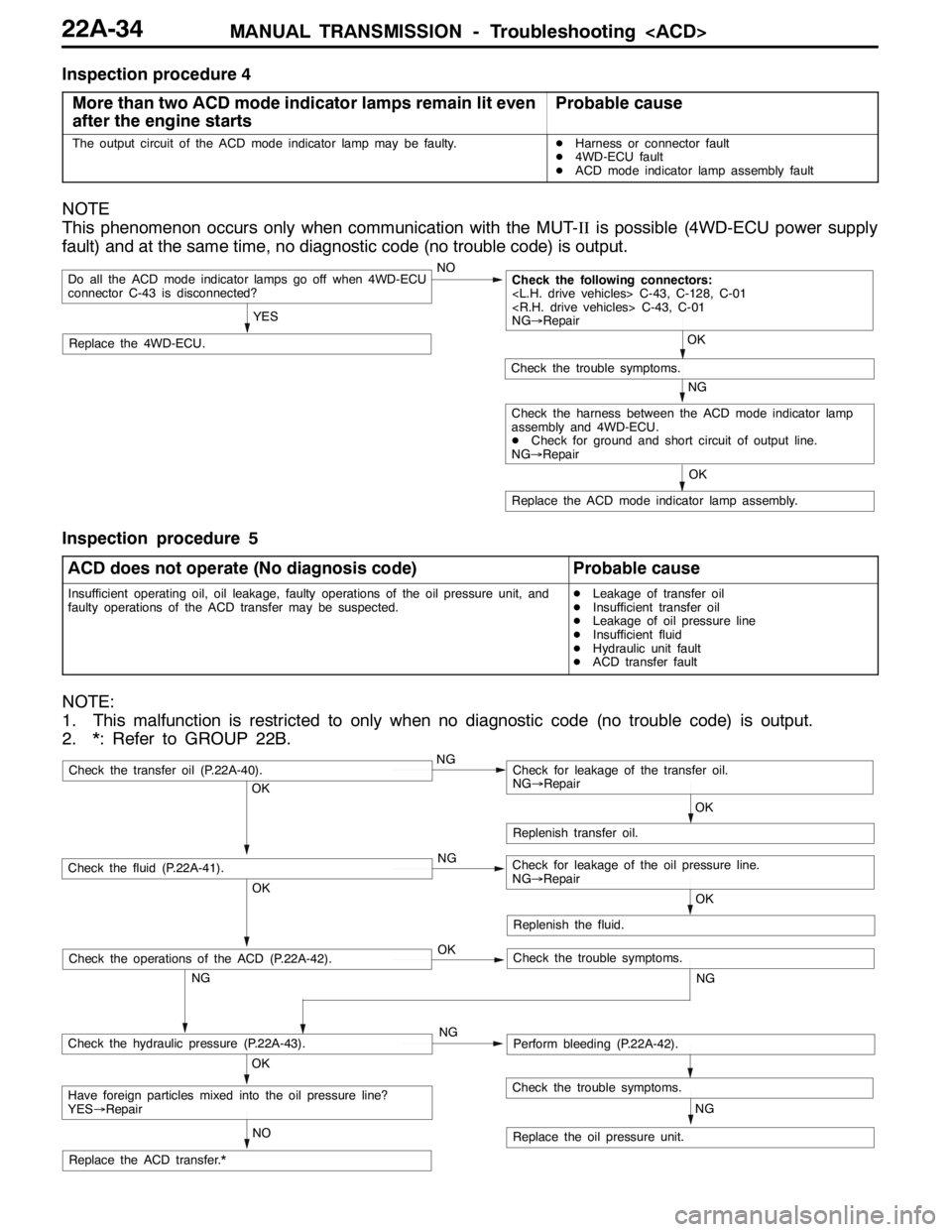
Inspection procedure 4
More than two ACD mode indicator lamps remain lit even
after the engine starts
Probable cause
The output circuit of the ACD mode indicator lamp may be faulty.DHarness or connector fault
D4WD-ECU fault
DACD mode indicator lamp assembly fault
NOTE
This phenomenon occurs only when communication with the MUT-IIis possible (4WD-ECU power supply
fault) and at the same time, no diagnostic code (no trouble code) is output.
NO
Replace the 4WD-ECU.
Do all the ACD mode indicator lamps go off when 4WD-ECU
connector C-43 is disconnected?
YES
Replace the ACD mode indicator lamp assembly.OK
NG
Check the trouble symptoms.
Check the following connectors:
NG→Repair
OK
Check the harness between the ACD mode indicator lamp
assembly and 4WD-ECU.
DCheck for ground and short circuit of output line.
NG→Repair
Inspection procedure 5
ACD does not operate (No diagnosis code)
Probable cause
Insufficient operating oil, oil leakage, faulty operations of the oil pressure unit, and
faulty operations of the ACD transfer may be suspected.DLeakage of transfer oil
DInsufficient transfer oil
DLeakage of oil pressure line
DInsufficient fluid
DHydraulic unit fault
DACD transfer fault
NOTE:
1. This malfunction is restricted to only when no diagnostic code (no trouble code) is output.
2. *: Refer to GROUP 22B.
OK
NG OKNG OKNG
NG
NO
NG
OK
Replenish transfer oil.
Replace the oil pressure unit.
Have foreign particles mixed into the oil pressure line?
YES→Repair
Check the hydraulic pressure (P.22A-43).Perform bleeding (P.22A-42).
Check the fluid (P.22A-41).Check for leakage of the oil pressure line.
NG→Repair
Check the transfer oil (P.22A-40).Check for leakage of the transfer oil.
NG→Repair
Check the trouble symptoms.
Replace the ACD transfer.*OK
Replenish the fluid.
OK
NG
Check the operations of the ACD (P.22A-42).Check the trouble symptoms.