Page 28 of 1449

BODY DIMENSIONS -Body Dimensions and Measurement MethodsB-2
BODY DIMENSIONS AND
MEASUREMENT METHODS
1. Type A (projected dimensions)
Indicates the dimension when a measurement location
is projected onto a plane.
The difference in height of the measurement points should
be taken into consideration when measuring.
2. Type B (actual-measurement dimensions)
Indicates the actual distance between the measurement
points.
Measure using a tracking gauge or a measuring tape,
etc.
NOTE
DMake the lengths of the tracking gauge probes the
same (A=A’).
DDo not bend or twist the measuring tape.
3. Insert the tracking gauge probes securely into the
measurement holes
4. When the standard dimensions in the illustration are
enclosed by, this indicates that the symmetrical left and
right positions have the same dimensions.
5. When using a notch for dimension measurement, set
the measuring point at the centre of the notch.
6. When measuring the suspension mounting arm, or link
mounting position, use the suspension mounting bolt,
etc..
7. The body centre points are shown for the purpose of
checking the position of the left and right symmetry
locations.Height
Probe
Projecteddimension
A’
Actually-measured
dimension
A
Centre
of hole
Bolt
Measuring point
Page 395 of 1449
GENERAL -Major Specifications00-17
MAJOR SPECIFICATIONS
1
234
5
6 78
9
ItemsCT9A
SNDFZL/RSNGFZL/R
Vehicle
di i
Front track11,500, 1,515*1
dimensions
mmOverall width21,770mm
Front overhang3895
Wheel base42,625
Rear overhang5935
Overall length64,455
Ground clearance
(unladen)7140
Overall height (unladen)81,450
Rear track91,500, 1,515*1
Vehicle
ihtk
Kerb weight1,3201,380
weight kgMax. gross vehicle weight1,6551,695
Max. axle weight
rating-front950970
Max. axle weight
rating-rear705725
Seating capacity5
EngineModel No.4G63g
Total displacement mL1,997
Transmis-
i
Model No.W5M51
sionType5-speed manual
Fuel systemFuel supply systemMPI
NOTE
*1: Vehicles with 17 inch wheels.
Page 404 of 1449

GENERAL -Support Locations for Lifting and Jacking00-26
PLATE TYPE LIFT
To avoid damaging the side sill garnish, put a wooden block between the side sill and a lift.
NOTE
The wooden block should be 100 mm wide and 50 mm high.
SUPPORT POSITIONS AND SUPPORT METHOD
FOR AN H-BAR LIFT
Caution
When service procedures require removing the rear
suspension, fuel tank, spare tyre and rear bumper, place
additional weight on rear end of vehicle or anchor vehicle
to hoist to prevent tipping of centre of gravity changes.
When H-bar lift is used to lift up vehicles, use of metallic
attachment attached to the H-bar lift may cause damage
to the suspension arm etc. Therefore, lift up the vehicle by
the following procedure.
1. Place the vehicle on the H-bar lift (same direction).
2. Place attachments on the H-bar lift at the designated
chassis-support positions. When making the attachments,
refer to the section concerning making them.
Caution
If support is at any location other than the designated
positions, the body or suspension might be deformed
or otherwise damaged, so care should be taken to
support only at the correct (designated) positions.
3. Raise the H-bar lift to the height at which the vehicle
is slightly raised and check to be sure that the vehicle
is correctly and sufficiently secured; then raise the vehicle.
H-bar lift
H-bar lift
A
Chassis-sup-
port position
(side sill)
Attachment
H-bar liftSection A - A
Side sill
AttachmentH-bar lift
A
Page 457 of 1449

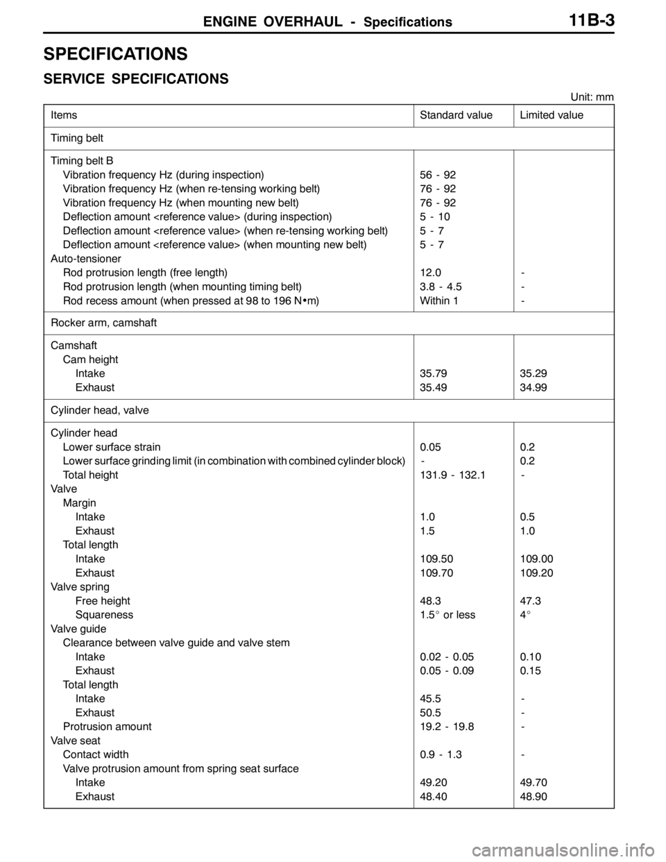
ENGINE OVERHAUL -Specifications11B-3
SPECIFICATIONS
SERVICE SPECIFICATIONS
Unit: mm
Items
Standard valueLimited value
Timing belt
Timing belt B
Vibration frequency Hz (during inspection)
Vibration frequency Hz (when re-tensing working belt)
Vibration frequency Hz (when mounting new belt)
Deflection amount (during inspection)
Deflection amount (when re-tensing working belt)
Deflection amount (when mounting new belt)
Auto-tensioner
Rod protrusion length (free length)
Rod protrusion length (when mounting timing belt)
Rod recess amount (when pressed at 98 to 196 N•m)
56 - 92
76 - 92
76 - 92
5-10
5-7
5-7
12.0
3.8 - 4.5
Within 1
-
-
-
Rocker arm, camshaft
Camshaft
Cam height
Intake
Exhaust
35.79
35.4935.29
34.99
Cylinder head, valve
Cylinder head
Lower surface strain
Lower surface grinding limit (in combination with combined cylinder block)
Total height
Valve
Margin
Intake
Exhaust
Total length
Intake
Exhaust
Valve spring
Free height
Squareness
Valve guide
Clearance between valve guide and valve stem
Intake
Exhaust
Total length
Intake
Exhaust
Protrusion amount
Valve seat
Contact width
Valve protrusion amount from spring seat surface
Intake
Exhaust
0.05
-
131.9 - 132.1
1.0
1.5
109.50
109.70
48.3
1.5_or less
0.02 - 0.05
0.05 - 0.09
45.5
50.5
19.2 - 19.8
0.9 - 1.3
49.20
48.400.2
0.2
-
0.5
1.0
109.00
109.20
47.3
4_
0.10
0.15
-
-
-
-
49.70
48.90
Page 491 of 1449
ENGINE OVERHAUL -Rocker Arm and Camshaft11B-37
INSPECTION
1. CAMSHAFT
Measure the cam height (length). Replace if it exceeds
the limit value.
Standard value:
Intake 35.79 mm
Exhaust 35.49 mm
Limit value:
Intake 35.29 mm
Exhaust 34.99 mm
2. LASH ADJUSTER
Caution
(1) The lash adjuster is a sophisticated part, so make
sure that foreign matter, such as dirt, does not
enter it.
(2) Do not disassemble the lash adjuster.
(3) When cleaning the lash adjuster, use clean diesel
oil.
(1) Prepare three vats and approx. five litres of diesel
oil.
Fill the vats with diesel oil so that the lash adjuster
will be submerged when placed standing in the vat.
(2) Submerge the lash adjuster in vat A, and clean the
outside.
NOTE
Use a nylon brush if the lash adjuster is heavily
contaminated.
For
preliminary
cleaningFor
cleaningFor
filling
diesel oil
ABC
Diesel oil
Page 497 of 1449

ENGINE OVERHAUL -Cylinder Head and Valve11B-43
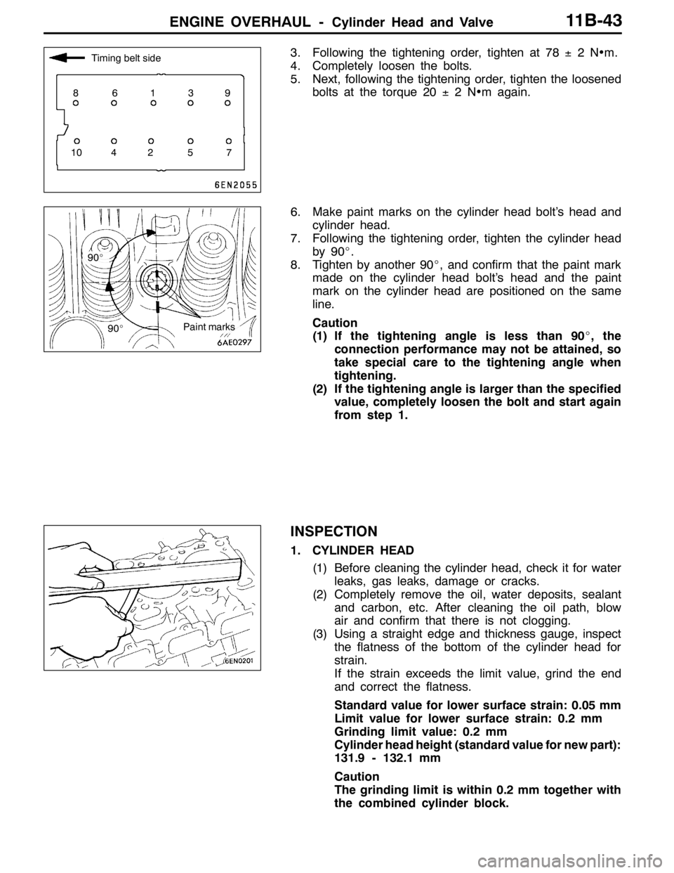
3. Following the tightening order, tighten at 78±2N•m.
4. Completely loosen the bolts.
5. Next, following the tightening order, tighten the loosened
bolts at the torque 20±2N•m again.
6. Make paint marks on the cylinder head bolt’s head and
cylinder head.
7. Following the tightening order, tighten the cylinder head
by 90_.
8. Tighten by another 90_, and confirm that the paint mark
made on the cylinder head bolt’s head and the paint
mark on the cylinder head are positioned on the same
line.
Caution
(1) If the tightening angle is less than 90_, the
connection performance may not be attained, so
take special care to the tightening angle when
tightening.
(2) If the tightening angle is larger than the specified
value, completely loosen the bolt and start again
from step 1.
INSPECTION
1. CYLINDER HEAD
(1) Before cleaning the cylinder head, check it for water
leaks, gas leaks, damage or cracks.
(2) Completely remove the oil, water deposits, sealant
and carbon, etc. After cleaning the oil path, blow
air and confirm that there is not clogging.
(3) Using a straight edge and thickness gauge, inspect
the flatness of the bottom of the cylinder head for
strain.
If the strain exceeds the limit value, grind the end
and correct the flatness.
Standard value for lower surface strain: 0.05 mm
Limit value for lower surface strain: 0.2 mm
Grinding limit value: 0.2 mm
Cylinder head height (standard value for new part):
131.9 - 132.1 mm
Caution
The grinding limit is within 0.2 mm together with
the combined cylinder block.
Timing belt side
86139
10 4 2 5 7
90_
90_
Paint marks
Page 498 of 1449

ENGINE OVERHAUL -Cylinder Head and Valve11B-44
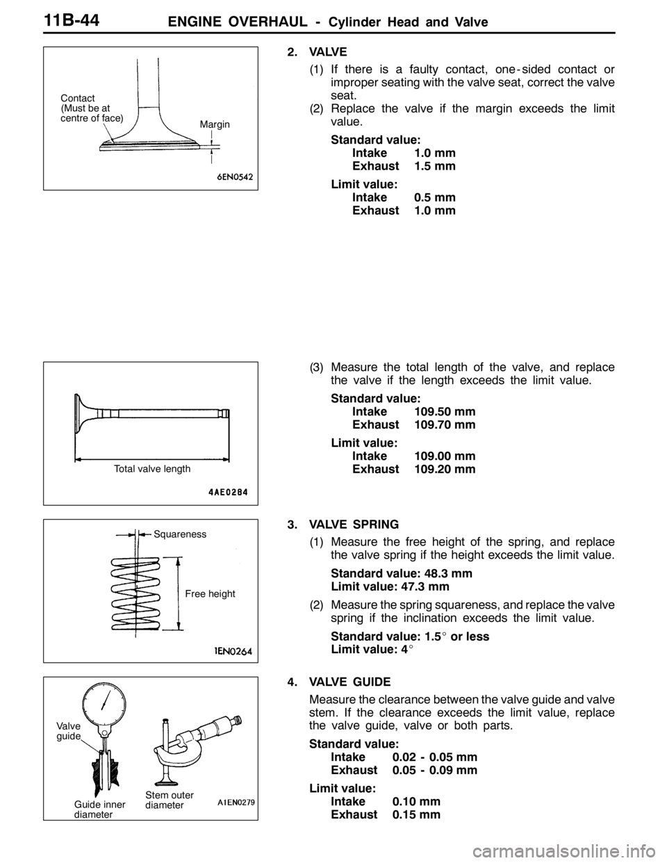
2. VALVE
(1) If there is a faulty contact, one - sided contact or
improper seating with the valve seat, correct the valve
seat.
(2) Replace the valve if the margin exceeds the limit
value.
Standard value:
Intake 1.0 mm
Exhaust 1.5 mm
Limit value:
Intake 0.5 mm
Exhaust 1.0 mm
(3) Measure the total length of the valve, and replace
the valve if the length exceeds the limit value.
Standard value:
Intake 109.50 mm
Exhaust 109.70 mm
Limit value:
Intake 109.00 mm
Exhaust 109.20 mm
3. VALVE SPRING
(1) Measure the free height of the spring, and replace
the valve spring if the height exceeds the limit value.
Standard value: 48.3 mm
Limit value: 47.3 mm
(2) Measure the spring squareness, and replace the valve
spring if the inclination exceeds the limit value.
Standard value: 1.5_or less
Limit value: 4_
4. VALVE GUIDE
Measure the clearance between the valve guide and valve
stem. If the clearance exceeds the limit value, replace
the valve guide, valve or both parts.
Standard value:
Intake 0.02 - 0.05 mm
Exhaust 0.05 - 0.09 mm
Limit value:
Intake 0.10 mm
Exhaust 0.15 mm
Contact
(Must be at
centre of face)
Margin
Total valve length
Squareness
Free height
Valve
guide
Stem outer
diameter Guide inner
diameter
Page 499 of 1449

ENGINE OVERHAUL -Cylinder Head and Valve11B-45
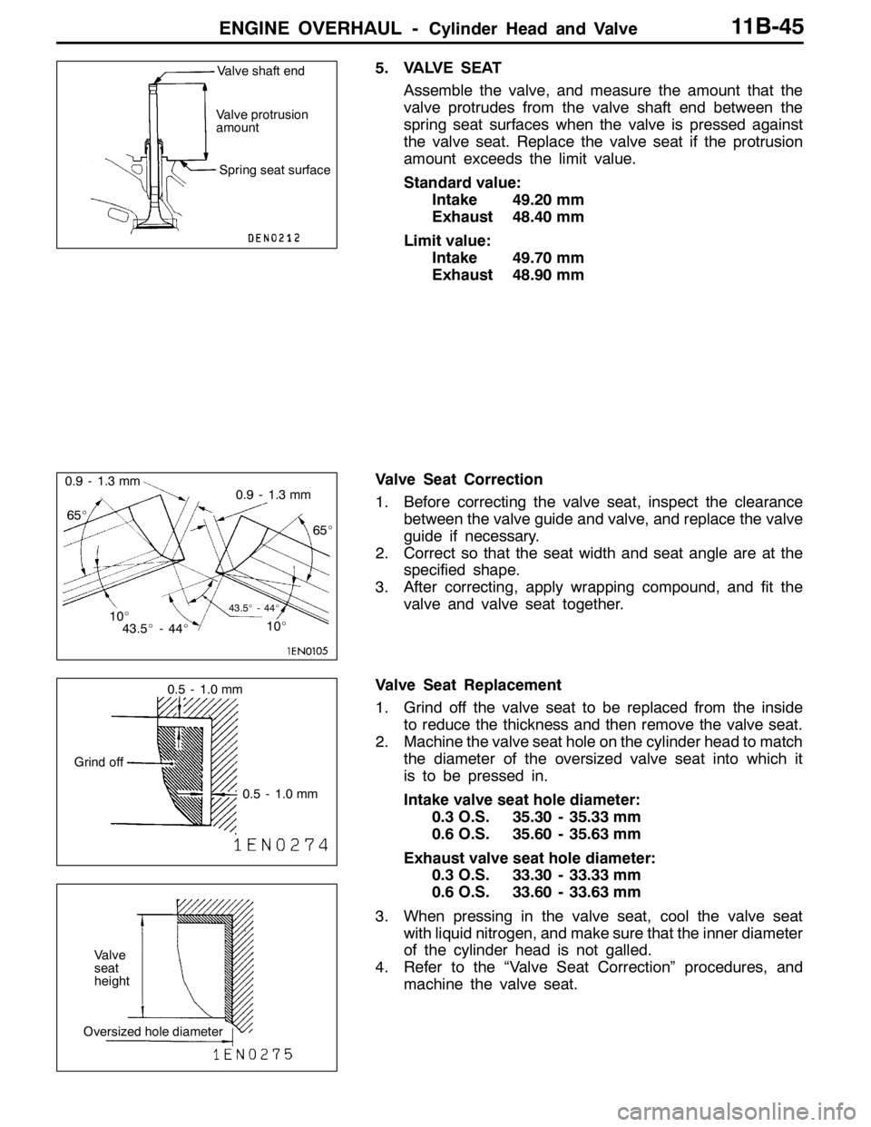
5. VALVE SEAT
Assemble the valve, and measure the amount that the
valve protrudes from the valve shaft end between the
spring seat surfaces when the valve is pressed against
the valve seat. Replace the valve seat if the protrusion
amount exceeds the limit value.
Standard value:
Intake 49.20 mm
Exhaust 48.40 mm
Limit value:
Intake 49.70 mm
Exhaust 48.90 mm
Valve Seat Correction
1. Before correcting the valve seat, inspect the clearance
between the valve guide and valve, and replace the valve
guide if necessary.
2. Correct so that the seat width and seat angle are at the
specified shape.
3. After correcting, apply wrapping compound, and fit the
valve and valve seat together.
Valve Seat Replacement
1. Grind off the valve seat to be replaced from the inside
to reduce the thickness and then remove the valve seat.
2. Machine the valve seat hole on the cylinder head to match
the diameter of the oversized valve seat into which it
is to be pressed in.
Intake valve seat hole diameter:
0.3 O.S. 35.30 - 35.33 mm
0.6 O.S. 35.60 - 35.63 mm
Exhaust valve seat hole diameter:
0.3 O.S. 33.30 - 33.33 mm
0.6 O.S. 33.60 - 33.63 mm
3. When pressing in the valve seat, cool the valve seat
with liquid nitrogen, and make sure that the inner diameter
of the cylinder head is not galled.
4. Refer to the “Valve Seat Correction” procedures, and
machine the valve seat.Valve shaft end
Spring seat surface Valve protrusion
amount
10_ 65_
10_65_ 0.9 - 1.3 mm
0.9 - 1.3 mm
43.5_-44_43.5_-44_
0.5 - 1.0 mm
0.5 - 1.0 mm Grind off
Valve
seat
height
Oversized hole diameter