Page 981 of 1449

REAR AXLE -Differential Carrier 27B-35
DIFFERENTIAL CARRIER
REMOVAL AND INSTALLATION
Pre-removal Operation
DDifferential Gear Oil Draining (Refer to P.27B-17.)
DLower Arm Assembly Removal (Refer to GROUP
34.)
DRear Stabilizer Removal (Refer to GROUP 34.)
DDrive Shaft Removal (Refer to P. 27B-29.)Post-installation Operation
DDrive Shaft Installation (Refer to P. 27B-29.)
DRear Stabilizer Installation (Refer to GROUP 34.)
DLower Arm Assembly Installation (Refer to GROUP
34.)
DDifferential Gear Oil Filling (Refer to P.27B-17.)
12
765
4 8 910
32�¶2N��m
2
3
3 3
3
76
9
120±10 N·m
88±10 N·m
69±9 N·m
88±10 N·m
88±10 N·m
88±10 N·m
120±10 N·m
120±10 N·m
120±10 N·m
69±9 N·m
88±10 N·m
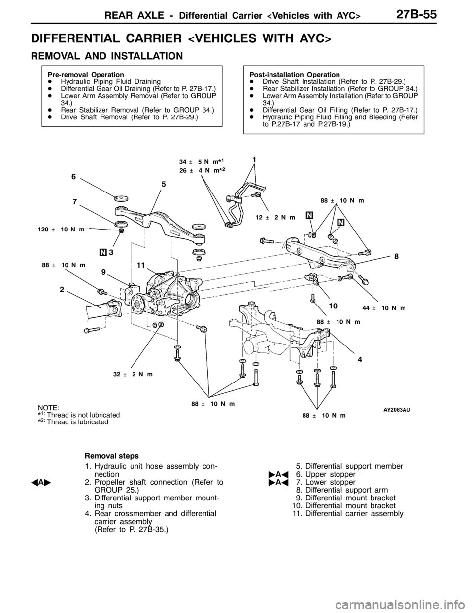
Removal steps
AA"1. Propeller shaft connection (Refer to
GROUP 25.)
2. Toe control bar
3. Differential support member mount-
ing boots and nuts
AB""AA4. Rear crossmember and differential
carrier assembly5. Differential support member
6. Upper stopper
7. Lower stopper
8. Differential support arm
9. Differential mount bracket
10. Differential carrier assembly
Page 1001 of 1449

REAR AXLE -Differential Carrier 27B-55
DIFFERENTIAL CARRIER
REMOVAL AND INSTALLATION
Pre-removal Operation
DHydraulic Piping Fluid Draining
DDifferential Gear Oil Draining (Refer to P. 27B-17.)
DLower Arm Assembly Removal (Refer to GROUP
34.)
DRear Stabilizer Removal (Refer to GROUP 34.)
DDrive Shaft Removal (Refer to P. 27B-29.)Post-installation Operation
DDrive Shaft Installation (Refer to P. 27B-29.)
DRear Stabilizer Installation (Refer to GROUP 34.)
DLower Arm Assembly Installation (Refer to GROUP
34.)
DDifferential Gear Oil Filling (Refer to P. 27B-17.)
DHydraulic Piping Fluid Filling and Bleeding (Refer
to P.27B-17 and P.27B-19.)
1
2
88�¶10 N��m
7 6
5
48
9
10 3
11
44�¶10 N��m
120�¶10 N��m34�¶5N��m*
1
32�¶2N��m
12�¶2N��m 26�¶4N��m*
2
88�¶10 N��m
88�¶10 N��m 88�¶10 N��m 88�¶10 N��mNOTE:
*1:Thread is not lubricated
*2:Thread is lubricated
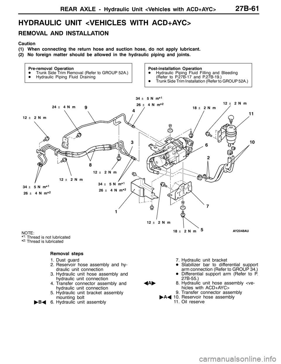
Removal steps
1. Hydraulic unit hose assembly con-
nection
AA"2. Propeller shaft connection (Refer to
GROUP 25.)
3. Differential support member mount-
ing nuts
4. Rear crossmember and differential
carrier assembly
(Refer to P. 27B-35.)5. Differential support member
"AA6. Upper stopper
"AA7. Lower stopper
8. Differential support arm
9. Differential mount bracket
10. Differential mount bracket
11. Differential carrier assembly
Page 1007 of 1449

REAR AXLE- Hydraulic Unit 27B-61
HYDRAULIC UNIT
REMOVAL AND INSTALLATION
Caution
(1) When connecting the return hose and suction hose, do not apply lubricant.
(2) No foreign matter should be allowed in the hydraulic piping and joints.
Pre-removal Operation
DTrunk Side Trim Removal (Refer to GROUP 52A.)
DHydraulic Piping Fluid DrainingPost-installation Operation
DHydraulic Piping Fluid Filling and Bleeding
(Refer to P.27B-17 and P.27B-19.)
DTrunk Side Trim Installation (Refer to GROUP 52A.)
12
7 6 4
8 9
10
311
34�¶5N��m*1
24�¶4N��m
12�¶2N��m
26�¶4N��m*
2
5
12�¶2N��m
12�¶2N��m
18�¶2N��m 34�¶5N��m*1
26�¶4N��m*2
18�¶2N��m12�¶2N��m 34�¶5N��m*
1
26�¶4N��m*2
12�¶2N��m
NOTE:
*1:Thread is not lubricated
*2:Thread is lubricated
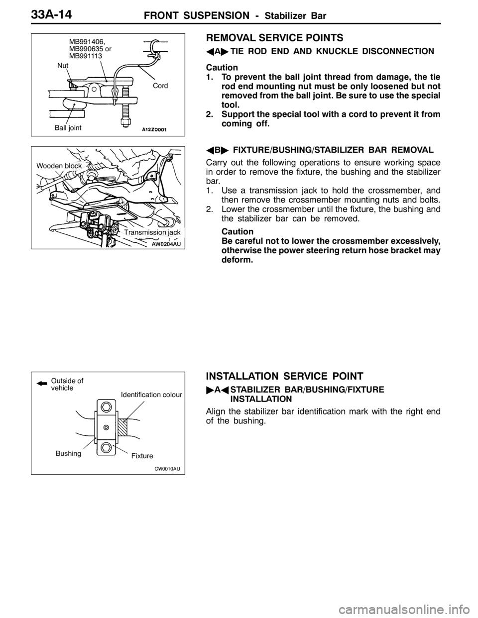
Removal steps
1. Dust guard
2. Reservoir hose assembly and hy-
draulic unit connection
3. Hydraulic unit hose assembly and
hydraulic unit connection
4. Transfer connector assembly and
hydraulic unit connection
5. Hydraulic unit bracket assembly
mounting bolt
"BA6. Hydraulic unit assembly7. Hydraulic unit bracket
DStabilizer bar to differential support
arm connection (Refer to GROUP 34.)
DDifferential support arm (Refer to P.
27B-55.)
AA"8. Hydraulic unit hose assembly
hicles with ACD+AYC>
9. Transfer connector assembly
"AA10. Reservoir hose assembly
11. Oil reserve
Page 1040 of 1449

FRONT SUSPENSION -Stabilizer Bar33A-14
REMOVAL SERVICE POINTS
AA"TIE ROD END AND KNUCKLE DISCONNECTION
Caution
1. To prevent the ball joint thread from damage, the tie
rod end mounting nut must be only loosened but not
removed from the ball joint. Be sure to use the special
tool.
2. Support the special tool with a cord to prevent it from
coming off.
AB"FIXTURE/BUSHING/STABILIZER BAR REMOVAL
Carry out the following operations to ensure working space
in order to remove the fixture, the bushing and the stabilizer
bar.
1. Use a transmission jack to hold the crossmember, and
then remove the crossmember mounting nuts and bolts.
2. Lower the crossmember until the fixture, the bushing and
the stabilizer bar can be removed.
Caution
Be careful not to lower the crossmember excessively,
otherwise the power steering return hose bracket may
deform.
INSTALLATION SERVICE POINT
"AASTABILIZER BAR/BUSHING/FIXTURE
INSTALLATION
Align the stabilizer bar identification mark with the right end
of the bushing.
Cord
Ball jointNut
MB991406,
MB990635 or
MB991113
Transmission jack
Woodenblock
Identification colour
BushingFixture
Outside of
vehicle