Page 435 of 1449
ENGINE -Cylinder Head Gasket11A-29
5.0±1.0 N·m
61
2
3 4
57
8
910
11 12
1314
13±1 N·m
15
16
17
5.0±1.0 N·m
1819
9.0±1.0 N·m
9.0±1.0 N·m
(Engine oil)
1
Removal steps
1. Ignition coil connector
2. Crank angle sensor connector
3. Oxygen sensor connector
4. Fuel pressure solenoid valve
connector
5. Detonation sensor connector
6. Purge control solenoid valve
connector
7. Throttle position sensor connector
8. Idle speed control servo connector
9. Injector connector
10. Camshaft position sensor connector
11. Engine coolant temperature gauge
unit connector12. Engine coolant temperature sensor
connector
DRocker cover (Refer to P.11A-17.)
13. EGR solenoid valve connector
14. Secondary air control solenoid valve
connector
15. Vacuum tank, solenoid valve, vacuum
pipe and hose assembly
16. Brake booster vacuum hose
connection
17. Oil level gauge and guide assembly
18. O-ring
19. Purge hose connection
Page 480 of 1449
ENGINE OVERHAUL -Fuel System11B-26
FUEL SYSTEM
REMOVAL AND INSTALLATION
1
11±1N•m
2
3
4 5
678
9 10
11 12 13
14 15
16
1718 1920 21
22
23
2425
11±1N•m
20±2N•m 19±3N•m
9±1N•m8.8±2.0 N•m
9±1N•m 9±1N•m
9±1N•m
Removal steps
1. Throttle body assembly
"CA2. Throttle body gasket
3. EGR valve
4. EGR gasket
5. Fuel hose
"BA6. Fuel pressure regulator
7. O-ring
8. Delivery pipe and injector
9. Insulator
10. Fuel return pipe
11. Insulator
"AA12. Injector
13. O-ring14. Grommet
15. Delivery pipe
16. Vacuum hose
17. Vacuum hose
18. Vacuum hose
19. Solenoid valve assembly
20. Solenoid valve assembly
21. Vacuum hose and pipe
22. Solenoid valve assembly
23. Vacuum tank bracket
24. Vacuum tank
25. Vacuum tank hose assembly
Page 683 of 1449

FUEL SUPPLY - On-vehicle Service/Fuel tank13B-3
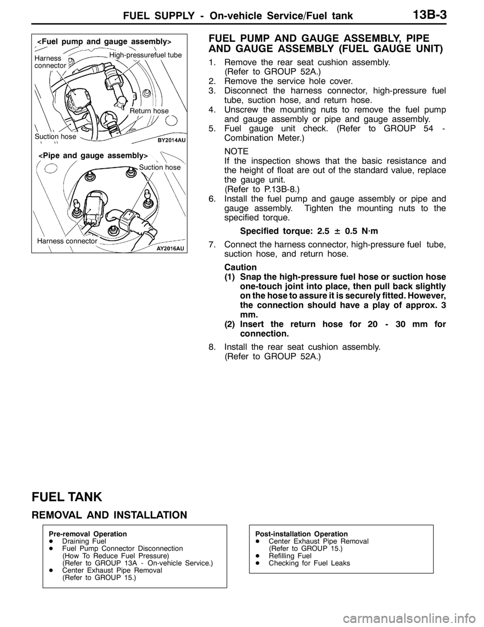
FUEL PUMP AND GAUGE ASSEMBLY, PIPE
AND GAUGE ASSEMBLY (FUEL GAUGE UNIT)
1. Remove the rear seat cushion assembly.
(Refer to GROUP 52A.)
2. Remove the service hole cover.
3. Disconnect the harness connector, high-pressure fuel
tube, suction hose, and return hose.
4. Unscrew the mounting nuts to remove the fuel pump
and gauge assembly or pipe and gauge assembly.
5. Fuel gauge unit check. (Refer to GROUP 54 -
Combination Meter.)
NOTE
If the inspection shows that the basic resistance and
the height of float are out of the standard value, replace
the gauge unit.
(Refer to P.13B-8.)
6. Install the fuel pump and gauge assembly or pipe and
gauge assembly. Tighten the mounting nuts to the
specified torque.
Specified torque: 2.5± 0.5 N·m
7. Connect the harness connector, high-pressure fuel tube,
suction hose, and return hose.
Caution
(1) Snap the high-pressure fuel hose or suction hose
one-touch joint into place, then pull back slightly
on the hose to assure it is securely fitted. However,
the connection should have a play of approx. 3
mm.
(2) Insert the return hose for 20 - 30 mm for
connection.
8. Install the rear seat cushion assembly.
(Refer to GROUP 52A.)
FUEL TANK
REMOVAL AND INSTALLATION
Pre-removal Operation
DDraining Fuel
DFuel Pump Connector Disconnection
(How To Reduce Fuel Pressure)
(Refer to GROUP 13A - On-vehicle Service.)
DCenter Exhaust Pipe Removal
(Refer to GROUP 15.)Post-installation Operation
DCenter Exhaust Pipe Removal
(Refer to GROUP 15.)
DRefilling Fuel
DChecking for Fuel Leaks
High-pressurefuel tubeHarness
connector
Suction hose
Return hose
Suction hose
Harness connector
Page 684 of 1449

FUEL SUPPLY - Fuel Tank13B-4
12
10
6 21
1
2
4
7 8
915 18
23 20
13 314
22
24 1119
5
16 175
2.5±0.5 N·m
2.5±0.5 N·m
26±4 N·m
22±4 N·m
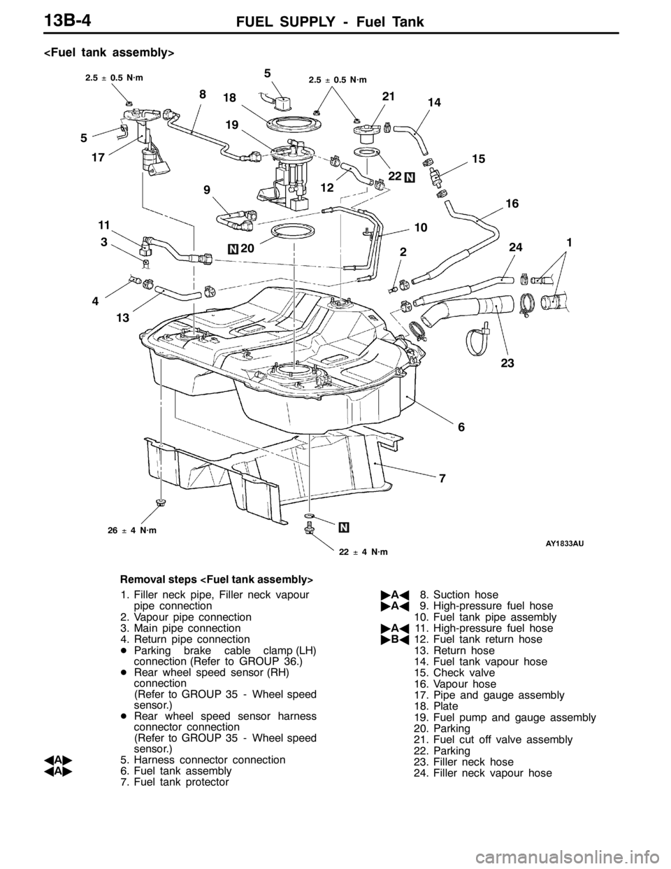
Removal steps
1. Filler neck pipe, Filler neck vapour
pipe connection
2. Vapour pipe connection
3. Main pipe connection
4. Return pipe connection
DParking brake cable clamp (LH)
connection (Refer to GROUP 36.)
DRear wheel speed sensor (RH)
connection
(Refer to GROUP 35 - Wheel speed
sensor.)
DRear wheel speed sensor harness
connector connection
(Refer to GROUP 35 - Wheel speed
sensor.)
AA"5. Harness connector connection
AA"6. Fuel tank assembly
7. Fuel tank protector"AA8. Suction hose
"AA9. High-pressure fuel hose
10. Fuel tank pipe assembly
"AA11. High-pressure fuel hose
"BA12. Fuel tank return hose
13. Return hose
14. Fuel tank vapour hose
15. Check valve
16. Vapour hose
17. Pipe and gauge assembly
18. Plate
19. Fuel pump and gauge assembly
20. Parking
21. Fuel cut off valve assembly
22. Parking
23. Filler neck hose
24. Filler neck vapour hose
Page 685 of 1449
FUEL SUPPLY - Fuel Tank13B-5
303128
25 29
2627
24±4 N·m
Removal steps
25. Filler neck protector
26. Filler neck hose connection
27. Filler neck vapour hose connection
28. Fuel filler cap29. Fuel filler neck assembly
30. Fuel shut-off valve
31. Parking
REMOVAL SERVICE POINT
AA"HARNESS CONNECTOR CONNECTION/FUEL
TANK ASSEMBLY DISCONNECTION
1. Remove the differential support member and tilt the
differential carrier.
(Refer to GROUP 27B.)
2. Hold the fuel tank with a transmission jack and remove
the nut connected to the fuel tank.
3. Tilt the fuel tank to allow access with a hand and disconnect
the harness connector.
4. Remove the fuel tank in the tilting direction to avoid contact
with the differential carrier.Fuel tankFloor
Differntial carrierRemoval
directionTilt
Page 687 of 1449
FUEL SUPPLY - Fuel Tank13B-7
DISASSEMBLY AND REASSEMBLY
1
2
34 567
9
8101112 13
Removal steps
1. Fuel gauge unit
2. Gauge harness
3. Bracket
4. Fuel pump cushion
5. Fuel pump
6. Spacer
"AA7. Grommet8. Assist pump
9. Fuel suction hose
10. Fuel return hose
11. Cap
"AA12. O-ring
13. Fuel filter assembly
Page 688 of 1449
FUEL SUPPLY - Fuel Tank13B-8
236
1 4
5
1.2±0.2 N·m
Removal steps
1. Packing
2. Filter
3. Gauge unit4. Connector
"AA5. O-ring
6. Pipe assembly
INSTALLATION SERVICE POINT
"AAO-RING/GROMMET INSTALLATION
Apply a fuel to O-ring and grommet before installing them,
to prevent them from being damaged or twisted.
Page 723 of 1449
INTAKE AND EXHAUST -Intake ManifoldINTAKE AND EXHAUST -Intake Manifold15-17
28 2325
26
2719
20 2221
23
24
30
23
29
20±2 N·m
20±2 N·m5.0±1.0 N·m
20±2 N·m
9.0±1.0 N·m
22±4 N·m 20±2 N·m 36±6 N·m
9.0±1.0 N·m
31±3 N·m 9.0±1.0 N·m 11±1 N·m
19. Vacuum hose
20. Fuel pressure solenoid valve
21. PCV hose
DAlternator (Refer to GROUP 16.)
22. Vacuum hose and Vacuum pipe
assembly connecting bolt
23. Vacuum tank, EGR solenoid valve,
Secondary air control solenoid
valve, Vacuum hose assembly24. Intake manifold stay
25. EGR valve
26. EGR gasket
27. Alternator brace stay
28. Intake manifold
29. Intake manifold gasket
30. Purge control solenoid valve
assembly
REMOVAL SERVICE POINTS
AA"DELIVERY PIPE, INJECTOR AND FUEL
PRESSURE REGULATOR ASSEMBLY REMOVAL
The delivery pipe must be removed with the injector and
fuel pressure regulator attached.
Caution
Take care not to drop delivery pipe, injector, or fuel
pressure regulator assembly when removing those parts.