Page 1009 of 1449
31-1
WHEEL AND TYRE
CONTENTS
GENERAL INFORMATION 2..................
SERVICE SPECIFICATIONS 2.................
TROUBLESHOOTING 3.......................ON-VEHICLE SERVICE 6.....................
Tyre Inflation Pressure Check 6.................
Tyre Wear Check 6............................
Wheel Runout Check 6.........................
WHEEL AND TYRE 6........................
Page 1010 of 1449
WHEEL AND TYRE -General Information/Service Specifications31-2
GENERAL INFORMATION
The wheels and tyres of the following specifications
have been established.
SPECIFICATIONS
ItemsRS (standard)RS (option), RS-II
WheelTypeSteel typeAluminium type
Size15×6JJ17×8JJ
Amount of wheel offset mm4638
Pitch circle diameter
(P.C.D.) mm114.3114.3
TyreSize205/65R15 94H235/45ZR17
Spare wheelTypeSteel typeSteel typep
Size16×4T17×4T
Amount of wheel offset mm4030
Pitch circle diameter
(P.C.D.) mm114.3114.3
Spare tyre (High pressure)SizeT125/70D16T125/70D17
SERVICE SPECIFICATIONS
ItemsLimit
Tread depth of tyre mm1.6
Wheel runout (Radial runout) mmSteel wheel1.2 or less
Aluminium wheel1.0 or less
Wheel runout (Lateral runout) mmSteel wheel1.2 or less
Aluminium wheel1.0 or less
Page 1011 of 1449
WHEEL AND TYRE -Troubleshooting31-3
TROUBLESHOOTING
SymptomProbable causeRemedyReference page
Rapid wear at
shouldersUnder-inflation
or lack of rotationAdjust the tyre
pressure.31-6
Rapid wear at
centreOver-inflation or
lack of rotation
Cracked treadsUnder-inflationAdjust the tyre
pressure.31-6
Wear on one
sideExcessive
camberInspect the
camber.Refer to
GROUP 33A -
On-vehicle
Service.
Feathered edgeIncorrect toe-inAdjust the toe-in.
Bald spotsUnbalanced
wheelAdjust the
imbalanced
wheels.31-4
Scalloped wearLack of rotation of tyres or worn or
out-of-alignment suspensionRotate the tyres
and check the
front suspension
alignment.Refer to
GROUP 33A -
On-vehicle
Service.
Page 1014 of 1449

WHEEL AND TYRE -On-vehicle Service/Wheel and Tyre31-6
ON-VEHICLE SERVICE
TYRE INFLATION PRESSURE CHECK
NOTE
For information on tyre inflation pressure, refer to the label
attached near the driver’s side door striker.
TYRE WEAR CHECK
Measure the tread depth of tyres.
Limit: 1.6 mm
If the remaining tread depth is less than the limit, replace
the tyre.
NOTE
When the tread depth of tyres is reduced to 1.6 mm or less,
wear indicators will appear.
WHEEL RUNOUT CHECK
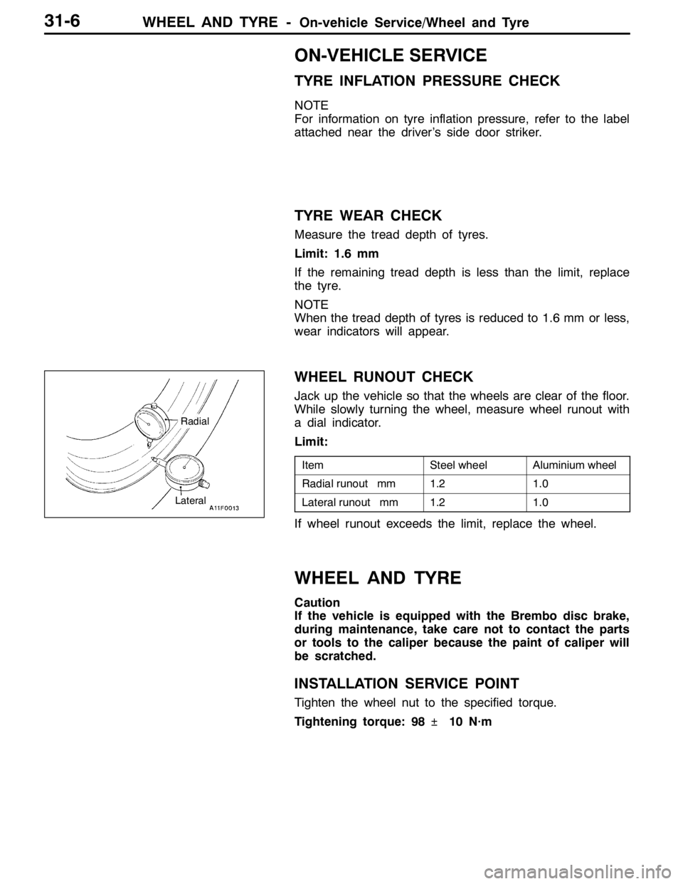
Jack up the vehicle so that the wheels are clear of the floor.
While slowly turning the wheel, measure wheel runout with
a dial indicator.
Limit:
ItemSteel wheelAluminium wheel
Radial runout mm1.21.0
Lateral runout mm1.21.0
If wheel runout exceeds the limit, replace the wheel.
WHEEL AND TYRE
Caution
If the vehicle is equipped with the Brembo disc brake,
during maintenance, take care not to contact the parts
or tools to the caliper because the paint of caliper will
be scratched.
INSTALLATION SERVICE POINT
Tighten the wheel nut to the specified torque.
Tightening torque: 98�¶10 N·m
Radial
Lateral
Page 1268 of 1449

SRS -Troubleshooting52B-24
OK
YESNO
Replace the driver’s seat belt pre-tensioner.
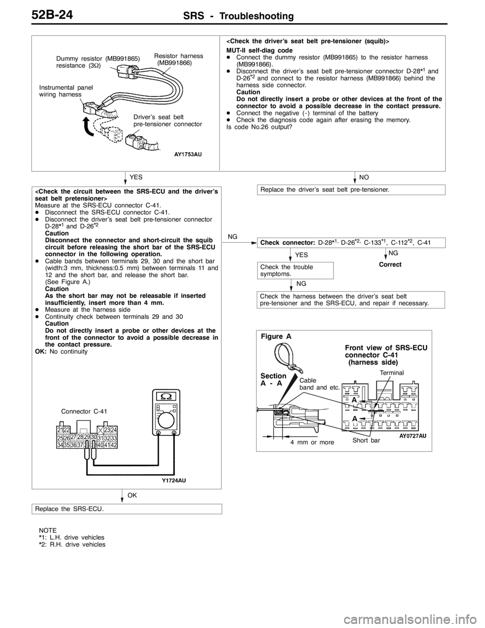
MUT-II self-diag code
DConnect the dummy resistor (MB991865) to the resistor harness
(MB991866).
DDisconnect the driver’s seat belt pre-tensioner connector D-28*
1and
D-26*2and connect to the resistor harness (MB991866) behind the
harness side connector.
Caution
Do not directly insert a probe or other devices at the front of the
connector to avoid a possible decrease in the contact pressure.
DConnect the negative ( - ) terminal of the battery
DCheck the diagnosis code again after erasing the memory.
Is code No.26 output?
Replace the SRS-ECU.
Check the trouble
symptoms.
NG
Check the harness between the driver’s seat belt
pre-tensioner and the SRS-ECU, and repair if necessary.
YESNG
Correct
Check connector:D-28*1,D-26*2,C-133*1, C-112*2, C-41 Driver’s seat belt
pre-tensioner connector
seat belt pretensioner>
Measure at the SRS-ECU connector C-41.
DDisconnect the SRS-ECU connector C-41.
DDisconnect the driver’s seat belt pre-tensioner connector
D-28*
1and D-26*2.Caution
Disconnect the connector and short-circuit the squib
circuit before releasing the short bar of the SRS-ECU
connector in the following operation.
DCable bands between terminals 29, 30 and the short bar
(width:3 mm, thickness:0.5 mm) between terminals 11 and
12 and the short bar, and release the short bar.
(See Figure A.)
Caution
As the short bar may not be releasable if inserted
insufficiently, insert more than 4 mm.
DMeasure at the harness side
DContinuity check between terminals 29 and 30
Caution
Do not directly insert a probe or other devices at the
front of the connector to avoid a possible decrease in
the contact pressure.
OK:No continuityResistor harness
(MB991866) Dummy resistor (MB991865)
resistance (3Ω)
Instrumental panel
wiring harness
Connector C-41NG
Figure A
Terminal
Short bar
Front view of SRS-ECU
connector C-41
(harness side)
Cable
band and etc.Section
A-A
4 mm or more
A
A
NOTE
*1: L.H. drive vehicles
*2: R.H. drive vehicles