Page 411 of 1449
ENGINE -Special Tools11A-5
SPECIAL TOOLS
ToolNumberNameUse
MB991502MUT-IIsub
assemblyDMeasuring the drive belt tension
DChecking the ignition timing
DChecking the idle speed
DErasing diagnosis code
DMeasuring the timing belt B tension
MB991668Belt tension meter
setDMeasuring the drive belt tension
(used together with MUT-II)
DMeasuring the timing belt B tension
(used together with MUT-II)
MD998727Oil pan removerFor removing the oil pan
MD998781Flywheel stopperFor fixing the flywheel
MD998776Crankshaft
rear oil seal
installerFor pressfitting the crankshaft rear oil seal
MB990938Installer bar
MD998285Crankshaft
front oil seal
guideFor pressfitting the crankshaft front oil seal
MD998382Crankshaft
front oil seal
installer
MB991654Cylinder head bolt
wrenchFor removal and installation of cylinder head
bolts
Page 439 of 1449
ENGINE -Cylinder Head Gasket11A-33
3. In case of not rotating smoothly, remove the fuel high
pressure hose and insert it to the delivery pipe again
after checking damage of the O-ring since there is a
possibility of O-ring engagement.
4. Tighten fuel high pressure hose mounting bolts to the
specified torque.
Tightening Torque: 5.0±1.0 N·m
"DAOIL RETURN PIPE GASKET INSTALLATION
Gasket should be replaced with a new one, and set the convex
part to the position as shown in the illustration for installation.
NOTE
There is no specific direction indicated for installing the
turbocharger side of the oil return pipe gasket.
Convex part
Page 448 of 1449

ENGINE -Timing belt and timing belt B11A-42
INSPECTION
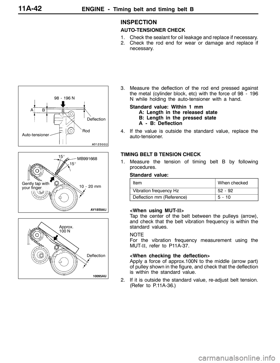
AUTO-TENSIONER CHECK
1. Check the sealant for oil leakage and replace if necessary.
2. Check the rod end for wear or damage and replace if
necessary.
3. Measure the deflection of the rod end pressed against
the metal (cylinder block, etc) with the force of 98 - 196
N while holding the auto-tensioner with a hand.
Standard value: Within 1 mm
A: Length in the released state
B: Length in the pressed state
A - B: Deflection
4. If the value is outside the standard value, replace the
auto-tensioner.
TIMING BELT B TENSION CHECK
1. Measure the tension of timing belt B by following
procedures.
Standard value:
ItemWhen checked
Vibration frequency Hz52 - 92
Deflection mm (Reference)5-10
Tap the center of the belt between the pulleys (arrow),
and check that the belt vibration frequency is within the
standard values.
NOTE
For the vibration frequency measurement using the
MUT-II, refer to P11A-37.
Apply a force of approx.100N to the middle (arrow part)
of pulley shown in the figure, and check that the deflection
is within the standard value.
2. If it is outside the standard value, re-adjust belt tension.
(Refer to P.11A-36.)
AB
Auto-tensioner
98 - 196 N
Deflection
Rod
MB991668
10 - 20 mm
15_
15_
Gently tap with
your finger
Deflection
Approx.
100 N
Page 453 of 1449

ENGINE -Engine Assembly11A-47
AD"ENGINE ASSEMBLY REMOVAL
After checking that all the cables, hoses, and harness
connectors have been disconnected, lift the engine with a
chain block slowly and remove the engine assembly located
at the upper engine room.
INSTALLATION SERVICE POINTS
"AAENGINE ASSEMBLY INSTALLATION
Install the engine assembly while checking that none of cables,
hoses, or harness connectors, etc. has been engaged.
"BAENGINE MOUNTING BRACKET AND STOPPER
ASSEMBLY INSTALLATION
1. Support the engine oil pan with a garage jack via a block
of wood cut adjusting the engine position and install the
engine mounting bracket and stopper assembly. Position
the engine mounting stopper so that a mark indicated
by an arrow can face the direction shown in the illustration.
2. Support engine with garage jack.
3. Remove the chain block and hold the engine assembly
with the special tool.(Tool used for removal of transmission
assembly)
"CAO-RING/FUEL HIGH PRESSURE HOSE
INSTALLATION
1. Apply small quantity of new engine oil on O-ring.
Caution
Do not let engine oil get into the delivery pipe.
2. Install the fuel high pressure pipe to the delivery pipe
rotating in both directions without damaging the O-ring
and check that it rotates smoothly.
3. In case of not rotating smoothly, remove the fuel high
pressure hose and insert it to the delivery pipe again
after checking damage of the O-ring since there is a
possibility of O-ring engagement.
4. Tighten fuel high pressure hose mounting bolt to the
specified torque.
Tightening Torque: 5.0±1.0 N·m
Engine mounting stopper
Engine side
Engine side
Page 489 of 1449

ENGINE OVERHAUL -Rocker Arm and Camshaft11B-35
REMOVAL SERVICE POINT
AA"LASH ADJUSTER REMOVAL
Caution
When reusing the lash adjuster, always clean and inspect
it before installing. (Refer to the section on checking the
lash adjuster.)
INSTALLATION SERVICE POINTS
"AALASH ADJUSTER INSTALLATION
Caution
When reusing the lash adjuster, always clean and inspect
it before installing. (Refer to the section on checking the
lash adjuster.)
Assembly the lash adjuster onto the rocker arm while taking
care not to spill out diesel oil in it.
"BACAMSHAFT INSTALLATION
1. Apply engine oil on the camshaft journal and cam.
2. Install the camshaft onto the cylinder head.
Caution
Do not mistake the intake and exhaust camshafts.
There is a 4 mm width slit on the back end of the
exhaust side camshaft.
"CABEARING CAP INSTALLATION
1. Set the camshaft’s dowel pin to the approximate top.
2. The bearing caps No. 2 to 5 have the same shape. Check
the identification symbol before installing to prevent
mistaking the cap No., intake side and exhaust side.
Identification symbol
(Stamped on front and on No. 2 to 5 bearing caps)
I : Intake side
E : Exhaust side
Timing belt side
Slit
Exhaust side
Dowel pins
Cap No.
Identification
of IN side and
EX side
Page 671 of 1449

MPI -On-vehicle Service13A-139
Checking the Coil Resistance
1. Disconnect the idle speed control servo connector.
2. Measure the resistance between terminal No. 2 and either
terminal No. 1 or terminal No. 3 of the connector at the
idle speed control servo side.
Standard value: 28 - 33Ω(at 20_C)
3. Measure the resistance between terminal No. 5 and either
terminal No. 6 or terminal No. 4 of the connector at the
idle speed control servo side.
Standard value: 28 - 33Ω(at 20_C)
Operation Check
1. Remove the throttle body.
2. Remove the stepper motor.
3. Connect the special tool (test harness: MB991709) to
the idle speed control servo connector.
4. Connect the positive (+) terminal of a power supply
(approximately 6 V) to the terminals No. 2 and No. 5.
5. With the idle speed control servo as shown in the
illustration, connect the negative ( - ) terminal of the power
supply to each clip as described in the following steps,
and check whether or not a vibrating feeling (a feeling
of very slight vibration of the stepper motor) is generated
as a result of the activation of the stepper motor.
(1) Connect the negative ( - ) terminal of the power supply
to the terminals No. 1 and No. 4.
(2) Connect the negative ( - ) terminal of the power supply
to the terminals No. 3 and No. 4.
(3) Connect the negative ( - ) terminal of the power supply
to the terminals No. 3 and No. 6.
(4) Connect the negative ( - ) terminal of the power supply
to the terminals No. 1 and No. 6
(5) Connect the negative ( - ) terminal of the power supply
to the terminals No. 1 and No. 4.
(6) Repeat the tests in sequence from (5) to (1).
6. If, as a result of these tests, vibration is detected, the
stepper motor can be considered to be normal.
Page 735 of 1449
ENGINE ELECTRICAL -Charging System16-3
ALTERNATOR SPECIFICATIONS
ItemsSpecifications
TypeBattery voltage sensing
Rated output V/A12/90
Voltage regulatorElectronic built-in type
SERVICE SPECIFICATIONS
ItemsStandard valueLimit
Alternator output line voltage drop (at 30 A) V-max. 0.3
Regulated voltage ambient
tempatvoltageregulatorV
-20_C14.2 - 15.4-
temp. atvoltage regulatorV
20_C13.9 - 14.9-
60_C13.4 - 14.6-
80_C13.1 - 14.5-
Output current-70 % of normal output current
Rotor coil resistanceΩApprox. 3 - 5-
Protrusion length of brush mm-2
SPECIAL TOOL
ToolNumberNameUse
MB991519Alternator test
harnessChecking the alternator (S terminal voltage)
Page 748 of 1449

ENGINE ELECTRICAL -Charging System16-16
RECTIFIERS CHECK
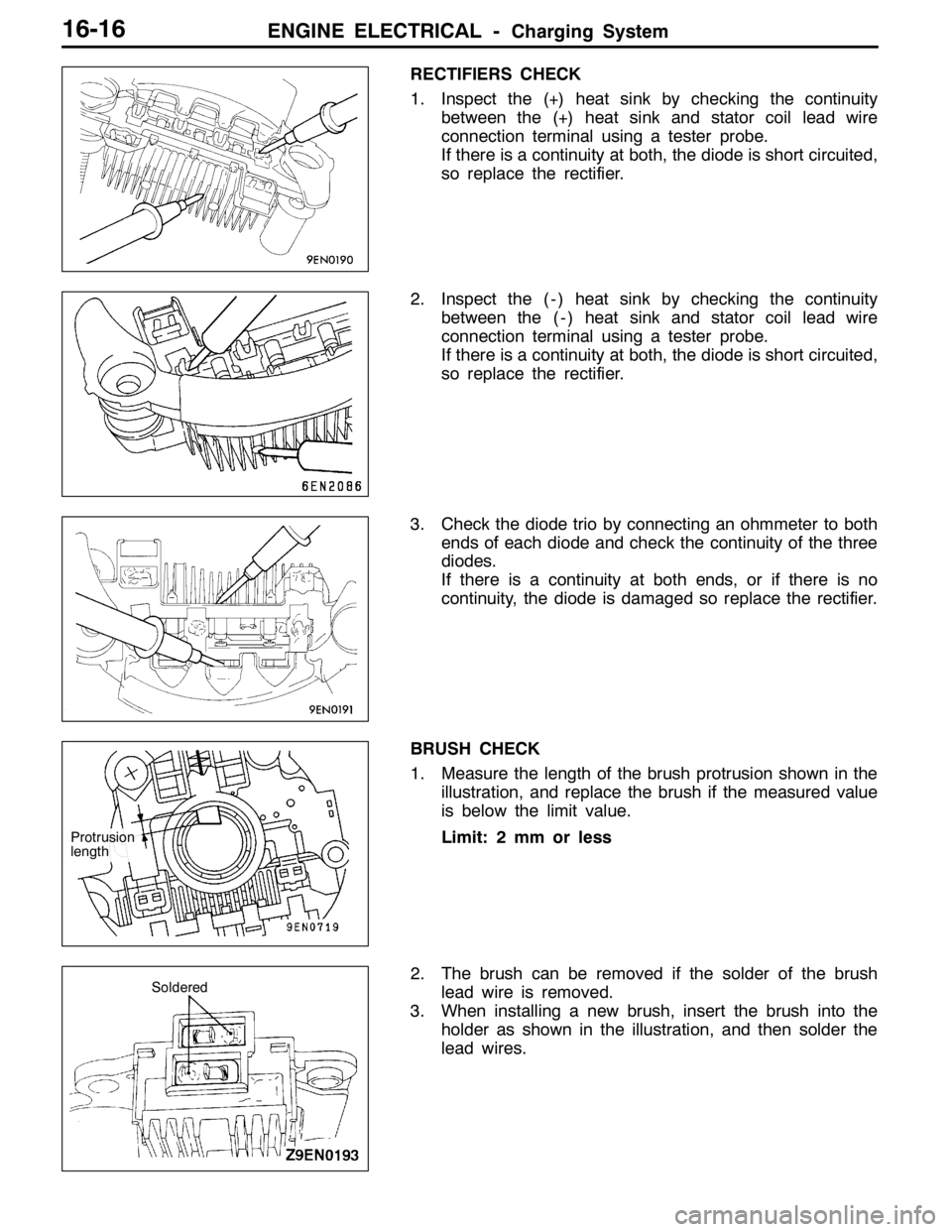
1. Inspect the (+) heat sink by checking the continuity
between the (+) heat sink and stator coil lead wire
connection terminal using a tester probe.
If there is a continuity at both, the diode is short circuited,
so replace the rectifier.
2. Inspect the ( - ) heat sink by checking the continuity
between the ( - ) heat sink and stator coil lead wire
connection terminal using a tester probe.
If there is a continuity at both, the diode is short circuited,
so replace the rectifier.
3. Check the diode trio by connecting an ohmmeter to both
ends of each diode and check the continuity of the three
diodes.
If there is a continuity at both ends, or if there is no
continuity, the diode is damaged so replace the rectifier.
BRUSH CHECK
1. Measure the length of the brush protrusion shown in the
illustration, and replace the brush if the measured value
is below the limit value.
Limit: 2 mm or less
2. The brush can be removed if the solder of the brush
lead wire is removed.
3. When installing a new brush, insert the brush into the
holder as shown in the illustration, and then solder the
lead wires.
Protrusion
length
Soldered