2007 MITSUBISHI LANCER EVOLUTION warning light
[x] Cancel search: warning lightPage 100 of 1449

B-2
S
PWGEE
IGNITION SYSTEM
L.H. drive vehicles 82.......................
R.H. drive vehicles 83.......................
CHARGING SYSTEM 84...................
ENGINE CONTROL SYSTEM
L.H. drive vehicles 86.......................
R.H. drive vehicles 94.......................
COOLING SYSTEM 102...................
HEADLAMP
L.H. drive vehicles 103......................
R.H. drive vehicles 106......................
TAIL LAMP, POSITION LAMP, LICENCE
PLATE LAMP AND LIGHTING MONITOR
BUZZER
L.H. drive vehicles 110......................
R.H. drive vehicles 114......................
ROOM LAMP AND LUGGAGE
COMPARTMENT LAMP
L.H. drive vehicles 118......................
R.H. drive vehicles 121......................
REAR FOG LAMP
L.H. drive vehicles 124......................
R.H. drive vehicles 127......................
HEADLAMP LEVELING SYSTEM
L.H. drive vehicles 130......................
R.H. drive vehicles 132......................
TURN-SIGNAL LAMP AND HAZARD
WARNING LAMP
L.H. drive vehicles 134......................
R.H. drive vehicles 138......................
BACK-UP LAMP
L.H. drive vehicles 142......................
R.H. drive vehicles 143......................
STOP LAMP
L.H. drive vehicles 144......................
R.H. drive vehicles 145......................
HORN 146................................
METER AND GAUGE
L.H. drive vehicles 148......................
R.H. drive vehicles 152......................
FUEL WARNING LAMP 156...............
OIL PRESSURE WARNING LAMP 157.....
BRAKE WARNING LAMP 157.............
POWER WINDOWS
L.H. drive vehicles 158......................
R.H. drive vehicles 164......................
CENTRAL DOOR LOCKING SYSTEM
L.H. drive vehicles 170......................
R.H. drive vehicles 172......................
HEATER AND MANUAL AIR CONDITIONER
L.H. drive vehicles 174......................
R.H. drive vehicles 180......................
DEFOGGER 185..........................
WINDSHIELD WIPER AND WASHER
L.H. drive vehicles 186......................
R.H. drive vehicles 189......................
REMOTE CONTROLLED MIRROR
L.H. drive vehicles 192......................
R.H. drive vehicles 193......................
CLOCK 194..............................
CIGARETTE LIGHTER AND ASHTRAY
ILLUMINATION LAMP 195.................
AUDIO SYSTEM 196......................
Page 167 of 1449

CIRCUIT DIAGRAMSB-69
DEDICATED FUSE
Power supply
circuitNo.Rated
capacity (A)Identification
colourCircuit
Battery/alternator
(FusiblelinkNo6)
115BlueSpare connectors
(FusiblelinkNo.6)210RedHorn relay
320YellowEngine control relay and ignition control relay
410RedA/C compressor
515BlueABS-ECU, 4WD-ECU, high-mounted stop lamp and rear
combination lamp
630GreenCondenser fan motor
77.5BrownAlternator
810RedETACS-ECU
9---
1015BlueFuel pump
Front-ECU
(Headlamprelay:
1110RedHeadlamp
(Headlamp relay:
HI)1210RedHeadlamp
Front-ECU
(Headlamprelay:
1310RedFront combination lamp
(Headlamp relay:
LO)1410RedFront combination lamp
Front-ECU
(Tail lamp relay)157.5BrownHeater control unit or A/C-ECU, clock, combination
meter, fog lamp switch, hazard warning switch, radio,
rear combination lamp, headlamp leveling switch, front
combination lamp, cigarette lighter illumination lamp,
ashtray illumination lamp, ACD mode changeover switch
and inter cooler water splay switch
167.5BrownFront combination lamp, licence plate lamp and rear
combination lamp
Ignition switch
(ACC)1710RedClock
Battery/alternator
(Fusible link No. 6)1810RedEngine-ECU, ETACS-ECU, front-ECU and combination
meter
-19---
Fusible link No. 52120YellowIntercooler water splay
-22---
Ignition switch
(IG2)23---
-24---
Battery/alternator
(Fusible link No. 6)2530GreenCondenser fan motor
Page 734 of 1449

ENGINE ELECTRICAL -Charging System16-2
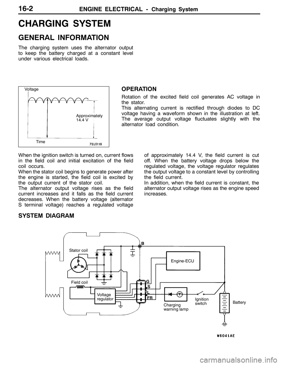
CHARGING SYSTEM
GENERAL INFORMATION
The charging system uses the alternator output
to keep the battery charged at a constant level
under various electrical loads.
OPERATION
Rotation of the excited field coil generates AC voltage in
the stator.
This alternating current is rectified through diodes to DC
voltage having a waveform shown in the illustration at left.
The average output voltage fluctuates slightly with the
alternator load condition.
When the ignition switch is turned on, current flows
in the field coil and initial excitation of the field
coil occurs.
When the stator coil begins to generate power after
the engine is started, the field coil is excited by
the output current of the stator coil.
The alternator output voltage rises as the field
current increases and it falls as the field current
decreases. When the battery voltage (alternator
S terminal voltage) reaches a regulated voltageof approximately 14.4 V, the field current is cut
off. When the battery voltage drops below the
regulated voltage, the voltage regulator regulates
the output voltage to a constant level by controlling
the field current.
In addition, when the field current is constant, the
alternator output voltage rises as the engine speed
increases.
SYSTEM DIAGRAM
Stator coil
Field coil
Voltage
regulatorEngine-ECU
Charging
warning lampIgnition
switchBattery B
G
L
FRS
Voltage
Time
Approximately
14.4 V
Page 737 of 1449

ENGINE ELECTRICAL -Charging System16-5
(6) Reconnect the negative battery cable.
(7) Connect a tachometer or the MUT-II.
(Refer to GROUP 11 - On-vehicle Service.)
(8) Leave the hood open.
(9) Start the engine.
(10)With the engine running at 2,500 r/min, turn
the headlamps and other lamps on and off
to adjust the alternator load so that the value
displayed on the ammeter is slightly above 30
A.
Adjust the engine speed by gradually
decreasing it until the value displayed on the
ammeter is 30 A. Take a reading of the value
displayed on the voltmeter at this time.
Limit: max. 0.3 V
NOTE
When the alternator output is high and the value
displayed on the ammeter does not decrease
until 30 A, set the value to 40 A. Read the
value displayed on the voltmeter at this time.
When the value range is 40 A, the limit is max.
0.4 V.(11) If the value displayed on the voltmeter is above
the limit value, there is probably a malfunction
in the alternator output wire, so check the wiring
between the alternator “B” terminal and the
battery (+) terminal (including fusible link).
If a terminal is not sufficiently tight or if the
harness has become discolored due to
overheating, repair and then test again.
(12)After the test, run the engine at idle.
(13)Turn off all lamps and the ignition switch.
(14)Remove the tachometer or the MUT-II.
(15)Disconnect the negative battery cable.
(16)Disconnect the ammeter and voltmeter.
(17)Connect the alternator output wire to the
alternator “B” terminal.
(18)Connect the negative battery cable.
OUTPUT CURRENT TEST
Charging warning lampVoltmeter
Ammeter
Ignition switch
Alternator relayLoad
Battery
Engine-ECUAlternatorFR
L
S
G
+ -+-
B
Page 819 of 1449

MANUAL TRANSMISSION - Troubleshooting
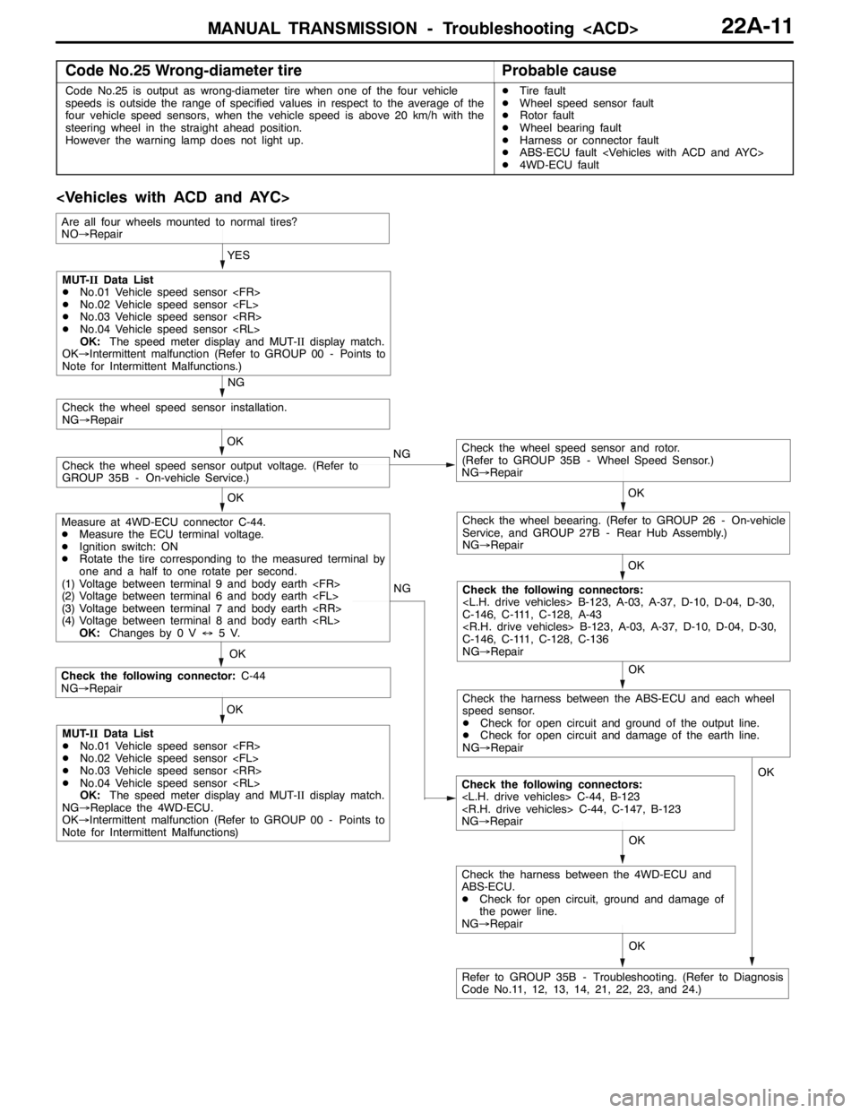
Code No.25 Wrong-diameter tireProbable cause
Code No.25 is output as wrong-diameter tire when one of the four vehicle
speeds is outside the range of specified values in respect to the average of the
four vehicle speed sensors, when the vehicle speed is above 20 km/h with the
steering wheel in the straight ahead position.
However the warning lamp does not light up.DTire fault
DWheel speed sensor fault
DRotor fault
DWheel bearing fault
DHarness or connector fault
DABS-ECU fault
D4WD-ECU fault
OK NG
OK
Check the following connector:C-44
NG→Repair
Check the following connectors:
NG→Repair OKYES
OK
OK
Check the wheel speed sensor and rotor.
(Refer to GROUP 35B - Wheel Speed Sensor.)
NG→Repair
Check the wheel speed sensor output voltage. (Refer to
GROUP 35B - On-vehicle Service.)OK
Check the wheel speed sensor installation.
NG→Repair
NG
OK
Check the wheel beearing. (Refer to GROUP 26 - On-vehicle
Service, and GROUP 27B - Rear Hub Assembly.)
NG→Repair
OK
Check the following connectors:
C-146, C-111, C-128, A-43
C-146, C-111, C-128, C-136
NG→Repair NG
MUT-IIData List
DNo.01 Vehicle speed sensor
DNo.02 Vehicle speed sensor
DNo.03 Vehicle speed sensor
DNo.04 Vehicle speed sensor
OK:The speed meter display and MUT-IIdisplay match.
OK→Intermittent malfunction (Refer to GROUP 00 - Points to
Note for Intermittent Malfunctions.)
Measure at 4WD-ECU connector C-44.
DMeasure the ECU terminal voltage.
DIgnition switch: ON
DRotate the tire corresponding to the measured terminal by
one and a half to one rotate per second.
(1) Voltage between terminal 9 and body earth
(2) Voltage between terminal 6 and body earth
(3) Voltage between terminal 7 and body earth
(4) Voltage between terminal 8 and body earth
OK:Changes by 0 V↔5V.
MUT-IIData List
DNo.01 Vehicle speed sensor
DNo.02 Vehicle speed sensor
DNo.03 Vehicle speed sensor
DNo.04 Vehicle speed sensor
OK:The speed meter display and MUT-IIdisplay match.
NG→Replace the 4WD-ECU.
OK→Intermittent malfunction (Refer to GROUP 00 - Points to
Note for Intermittent Malfunctions)
Refer to GROUP 35B - Troubleshooting. (Refer to Diagnosis
Code No.11, 12, 13, 14, 21, 22, 23, and 24.)
Are all four wheels mounted to normal tires?
NO→Repair
Check the harness between the ABS-ECU and each wheel
speed sensor.
DCheck for open circuit and ground of the output line.
DCheck for open circuit and damage of the earth line.
NG→Repair
OK
Check the harness between the 4WD-ECU and
ABS-ECU.
DCheck for open circuit, ground and damage of
the power line.
NG→RepairOK
Page 821 of 1449

MANUAL TRANSMISSION - Troubleshooting
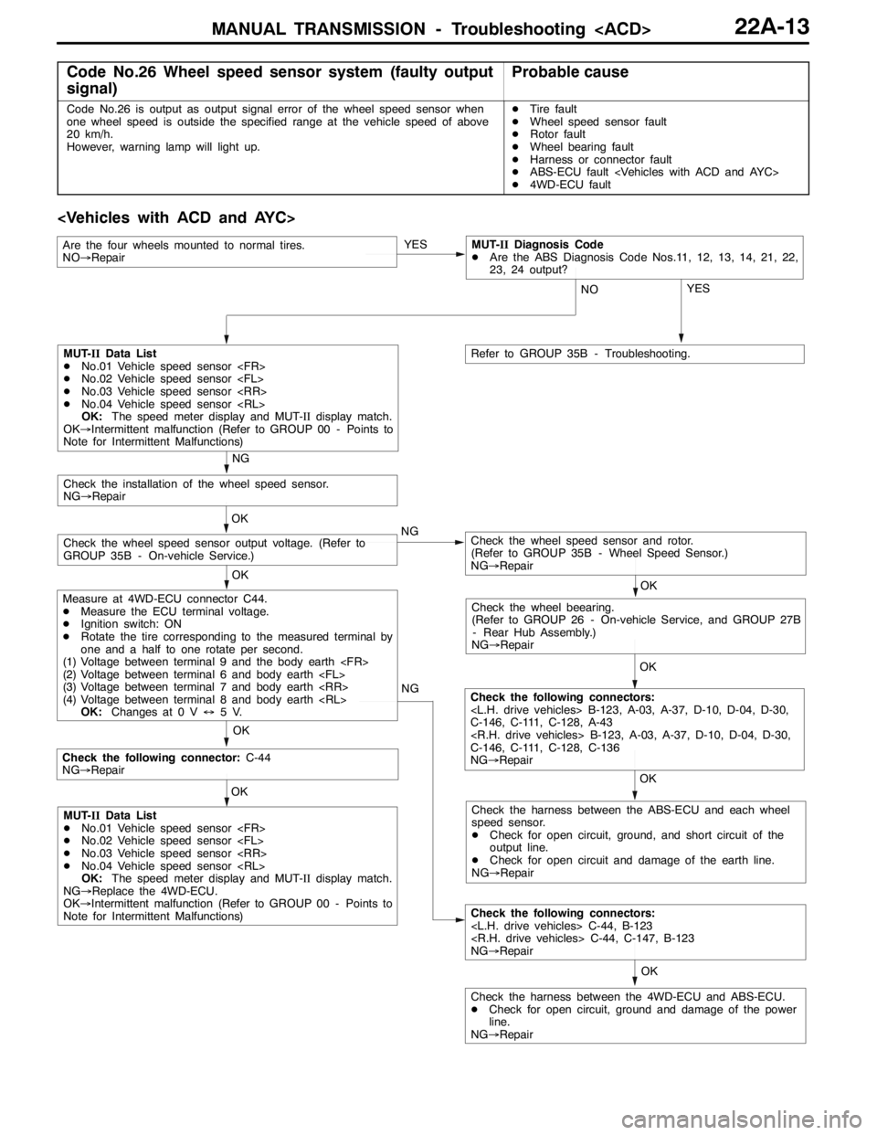
Code No.26 Wheel speed sensor system (faulty output
signal)Probable cause
Code No.26 is output as output signal error of the wheel speed sensor when
one wheel speed is outside the specified range at the vehicle speed of above
20 km/h.
However, warning lamp will light up.DTire fault
DWheel speed sensor fault
DRotor fault
DWheel bearing fault
DHarness or connector fault
DABS-ECU fault
D4WD-ECU fault
OK NG
OK
Check the following connector:C-44
NG→Repair
Check the following connectors:
NG→Repair OK
Check the harness between the 4WD-ECU and ABS-ECU.
DCheck for open circuit, ground and damage of the power
line.
NG→RepairYES
OK OK
Check the wheel speed sensor and rotor.
(Refer to GROUP 35B - Wheel Speed Sensor.)
NG→RepairCheck the wheel speed sensor output voltage. (Refer to
GROUP 35B - On-vehicle Service.)OK
Check the installation of the wheel speed sensor.
NG→Repair
NG
OK
Check the wheel beearing.
(Refer to GROUP 26 - On-vehicle Service, and GROUP 27B
- Rear Hub Assembly.)
NG→Repair
OK
Check the following connectors:
C-146, C-111, C-128, A-43
C-146, C-111, C-128, C-136
NG→Repair NG
MUT-IIData List
DNo.01 Vehicle speed sensor
DNo.02 Vehicle speed sensor
DNo.03 Vehicle speed sensor
DNo.04 Vehicle speed sensor
OK:The speed meter display and MUT-IIdisplay match.
OK→Intermittent malfunction (Refer to GROUP 00 - Points to
Note for Intermittent Malfunctions)
Measure at 4WD-ECU connector C44.
DMeasure the ECU terminal voltage.
DIgnition switch: ON
DRotate the tire corresponding to the measured terminal by
one and a half to one rotate per second.
(1) Voltage between terminal 9 and the body earth
(2) Voltage between terminal 6 and body earth
(3) Voltage between terminal 7 and body earth
(4) Voltage between terminal 8 and body earth
OK:Changes at 0 V↔5V.
MUT-IIData List
DNo.01 Vehicle speed sensor
DNo.02 Vehicle speed sensor
DNo.03 Vehicle speed sensor
DNo.04 Vehicle speed sensor
OK:The speed meter display and MUT-IIdisplay match.
NG→Replace the 4WD-ECU.
OK→Intermittent malfunction (Refer to GROUP 00 - Points to
Note for Intermittent Malfunctions)Check the harness between the ABS-ECU and each wheel
speed sensor.
DCheck for open circuit, ground, and short circuit of the
output line.
DCheck for open circuit and damage of the earth line.
NG→Repair YES
NO
Refer to GROUP 35B - Troubleshooting.
Are the four wheels mounted to normal tires.
NO→RepairMUT-IIDiagnosis Code
DAre the ABS Diagnosis Code Nos.11, 12, 13, 14, 21, 22,
23, 24 output?
Page 1302 of 1449

SRS - Air Bag Modules and Clock Spring52B-58
"CASTEERING WHEEL/STEERING WHEEL - AIR BAG
MODULE ASSEMBLY INSTALLATION
1. After checking that centering of the clock spring has been
done, install the steering wheel or the steering wheel - air
bag module assembly.
Caution
Do not engage the harness of the clock spring when
installing the steering wheel or the steering wheel - air
bag module assembly.
2. After installation, check that no abnormalities occur when
the steering wheel is fully turned to the left or the right.
"DAPOST-INSTALLATION INSPECTION
1. Check that no abnormal noise or improper operation can
be caused by rotating the steering wheel in left and right
directions slightly.
(driver’s air bag module, clock spring)
2. Turn the ignition switch to the ON position.
3. Check that the SRS warning lamp illuminates for 6 to
8 seconds and goes out.
4. Carry out troubleshooting if the lamp does not go out.
(Refer to P.52-6.)
SRS warning lamp
Page 1323 of 1449

54A-3
SIDE TURN-SIGNAL LAMP 31............
SPECIAL TOOL 31............................
SIDE TURN-SIGNAL LAMP 31..................
ROOM LAMP 31.........................
TROUBLESHOOTING 31.......................
REAR COMBINATION LAMP 32...........
SPECIAL TOOL 32............................
TROUBLESHOOTING 32.......................
REAR COMBINATION LAMP 32................
HIGH-MOUNTED STOP LAMP 34.........
ON-VEHICLE SERVICE 34......................
High-mounted Stop Lamp Bulb Replacement 34.
HIGH-MOUNTED STOP LAMP 34................
LICENCE PLATE LAMP 35...............
ON-VEHICLE SERVICE 35.....................
License Plate Lamp Replacement 35...........
LICENCE PLATE LAMP 35.....................
HAZARD WARNING LAMP SWITCH 36....
SPECIAL TOOL 36............................
HAZARD WARNING LAMP SWITCH 36.........
HORN 37................................
CIGARETTE LIGHTER 37.................
COLUMN SWITCH 38....................
SPECIAL TOOL 38............................
COLUMN SWITCH 38..........................
CLOCK 40...............................
SPECIAL TOOL 40............................
CLOCK 40....................................
POLE ANTENNA 41......................
ROOF ANTENNA 42......................
DEFOGGER 42...........................
TROUBLESHOOTING 42......................
ON-VEHICLE SERVICE 43.....................
Printed Heater Check 43......................
Defogger Relay Continuity Check 43...........
DEFOGGER SWITCH 43.......................