2007 MITSUBISHI LANCER EVOLUTION clutch
[x] Cancel search: clutchPage 1 of 1449

00
11
12
13
14
15
16
17
21
22
25
26
27
31
32
33
34
35
36
37
42
51
52
54
55
General........................
Engine .........................
Engine Lubrication .............
Fuel ...........................
Engine Cooling .................
Intake and Exhaust ............
Engine Electrical ...............
Engine and Emission Control ....
Clutch .........................
Manual Transmission ...........
Propeller Shaft .................
Front Axle ......................
Rear Axle ......................
Wheel and Tyre .................
Power Plant Mount ..............
Front Suspension ...............
Rear Suspension ...............
Service Brakes .................
Parking Brakes .................
Steering ........................
Body ...........................
Exterior ........................
Chassis Electrical ..............
Electrical Wiring ................
Body Repair ....................
WORKSHOP
MANUAL
FOREWORD
This Workshop Manual contains procedures for
service mechanics, including removal, disassembly,
inspection, adjustment, reassembly and
installation. Use the following manuals in
combination with this manual as required.
TECHNICAL INFORMATION MANUAL N0104CT9A
All information, illustrations and product
descriptions contained in this manual are current
as at the time of publication. We, however, reserve
the right to make changes at any time without prior
notice or obligation.
The EVOLUTION-VII is sold exclusively through
RALLIART Inc. Since the EVOLUTION-VII is a
rally-based model, it will not be warranted and will
not be homologated for general production.
Therefore, any service matters on the
EVOLUTION-VII should be inquired to RALLIART
Inc. as usual.
EMitsubishi Motors Corporation May 2001
Interior and Supplemental
Restraint System (SRS) ........
Heater, Air Conditioner and
Ventilation .....................
Page 14 of 1449

BODY CONSTRUCTION -Body Construction CharacteristicsBODY CONSTRUCTION -Body Construction CharacteristicsA-12
Front Deck
Strut house gussetandupper frame to front pillar brace have been added to improve body rigidity.
7
1 24 56
8
9
310
11
12 13
14
15
16
1. Strut tower bar bracket
2. Cowl top lower panel
3. Cowl top upper bracket center
4. Cowl top upper reinforcement center
5. Cowl top upper bracket side (LHD)
6. Cowl top inner panel
7. Cowl top upper panel
8. Pedal support bracket9. Clutch pedal support bracket
10. A/C Unit bracket (RHD)
11. Upper frame extension outer
12. Upper frame to front pillar brace
13. Cowl top upper reinforcement
14. Cowl top lower bracket
15. Upper frame extension inner
16. Strut house gusset
Dash Panel
1. A dash panel crossmember has been added and the thickness of the dash panel lower has been
increased to improve collision stability.
2. A silencer (steel sheet binding type vibration damping material) has been added between the dash
panel and dash panel silencer to control the penetrating sound and vibration from the engine.
18 3
76 5 4
2
1. Dash panel crossmember
2. Dash panel
3. Dash silencer center
4. Dash panel silencer5. Accel pedal reinforcement (LHD)
6. Dash panel reinforcement
7. Dash lower reinforcement (LHD)
8. Dash panel lower
Page 432 of 1449

ENGINE -Crankshaft Oil Seal11A-26
CRANKSHAFT OIL SEAL
REMOVAL AND INSTALLATION
Caution
If the vehicle is equipped with the Brembo disc brake, during maintenance, take care not to contact
the parts or tools to the caliper because the paint of caliper will be scratched.
1 2
34 5
6
Engine oil
(at the lip)
(at the lip)
3
6
132±5 N·m
Crankshaft Front Oil Seal Removal
Steps
DTiming belt and timing belt B
(Refer to P.11A-34.)
"DA1. Crankshaft sprocket B
2. Key
"CA3. Crankshaft front oil sealCrankshaft Rear Oil Seal Removal
Steps
DTransfer assembly
(Refer to GROUP 22A.)
DTransmission assembly
(Refer to GROUP 22A.)
DClutch cover, disc
AA""BA4. Flywheel bolt
5. Flywheel
"AA6. Crankshaft rear oil seal
Page 536 of 1449

MPI -General Information13A-4
OTHER CONTROL FUNCTIONS
1. Fuel Pump Control
Turns the fuel pump relay ON so that current
is supplied to the fuel pump while the engine
is cranking or running.
2. A/C Relay Control
Turns the compressor clutch of the A/C
ON and OFF.3. Fan Motor Control
The revolutions of the radiator fan and
condenser fan are controlled in response to
the engine coolant temperature and vehicle
speed.
4. Purge Control Solenoid Valve Control
Refer to GROUP 17.
5. EGR Control Solenoid Valve Control
Refer to GROUP 17.
GENERAL SPECIFICATIONS
ItemsSpecifications
Throttle bodyThrottle bore mm60
Throttle position sensorVariable resistor type
Idle speed control servoStepper motor type
(Stepper motor type by-pass air control system with the
air volume limiter)
Engine-ECUIdentification No.E6T34874
SensorsAir flow sensorKarman vortex type
Barometric pressure sensorSemiconductor type
Intake air temperature sensorThermistor type
Engine coolant temperature sensorThermistor type
Oxygen sensorZirconia type
Vehicle speed sensorMagnetic resistive element type
Camshaft position sensorHall element type
Crank angle sensorHall element type
Detonation sensorPiezoelectric type
Power steering fluid pressure switchContact switch type
ActuatorsEngine control relay typeContact switch type
Fuel pump relay typeContact switch type
Injector type and numberElectromagnetic type, 4
Injector identification markMDL560
EGR control solenoid valveDuty cycle type solenoid valve
Purge control solenoid valveDuty cycle type solenoid valve
Fuel pressure control solenoid valveON/OFF type solenoid valve
Waste gate solenoid valveDuty cycle type solenoid valve
Secondary air control solenoid valveON/OFF type solenoid valve
Fuel pressure
regulatorRegulator pressure kPa294
Page 613 of 1449

MPI -Troubleshooting13A-81
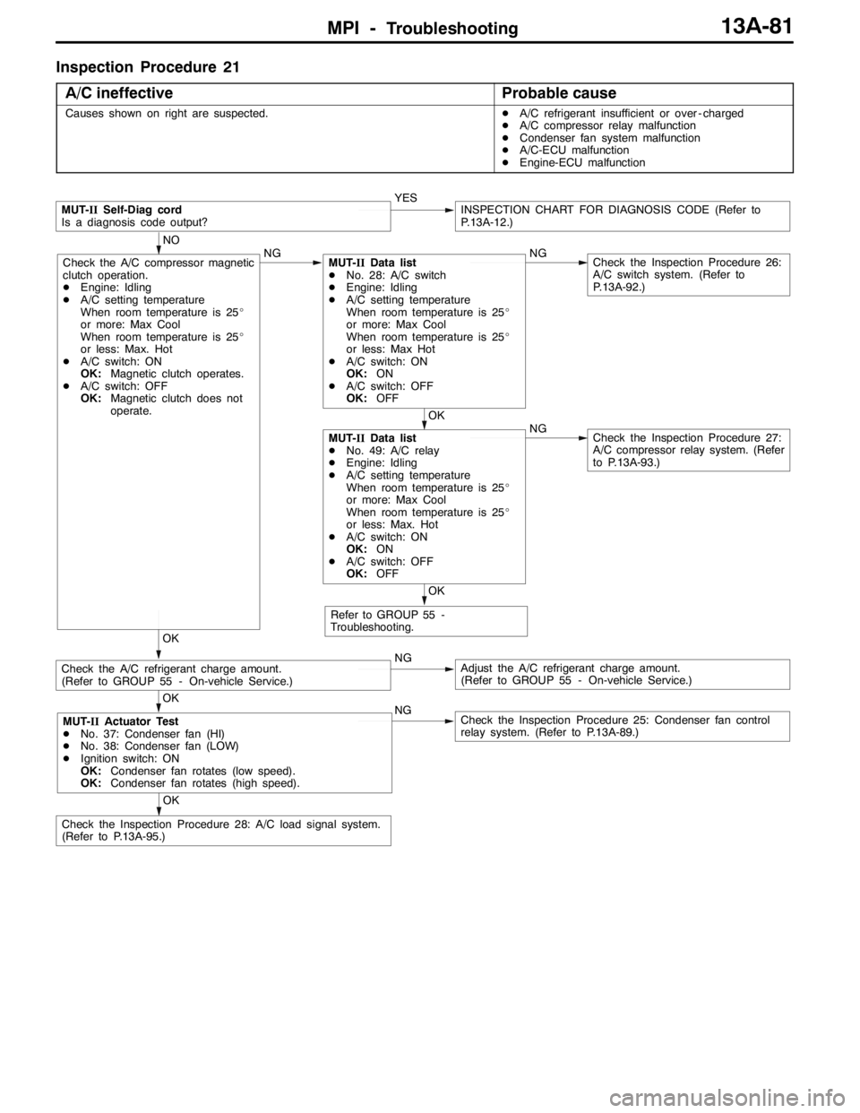
Inspection Procedure 21
A/C ineffective
Probable cause
Causes shown on right are suspected.DA/C refrigerant insufficient or over - charged
DA/C compressor relay malfunction
DCondenser fan system malfunction
DA/C-ECU malfunction
DEngine-ECU malfunction
NGCheck the Inspection Procedure 25: Condenser fan control
relay system. (Refer to P.13A-89.)
NGAdjust the A/C refrigerant charge amount.
(Refer to GROUP 55 - On-vehicle Service.)
MUT-IISelf-Diag cord
Is a diagnosis code output?YESINSPECTION CHART FOR DIAGNOSIS CODE (Refer to
P.13A-12.)
Refer to GROUP 55 -
Troubleshooting.
OK
OK
Check the A/C compressor magnetic
clutch operation.
DEngine: Idling
DA/C setting temperature
When room temperature is 25_
or more: Max Cool
When room temperature is 25_
or less: Max. Hot
DA/C switch: ON
OK:Magnetic clutch operates.
DA/C switch: OFF
OK:Magnetic clutch does not
operate.NGMUT-IIData list
DNo. 28: A/C switch
DEngine: Idling
DA/C setting temperature
When room temperature is 25_
or more: Max Cool
When room temperature is 25_
or less: Max Hot
DA/C switch: ON
OK:ON
DA/C switch: OFF
OK:OFFNGCheck the Inspection Procedure 26:
A/C switch system. (Refer to
P.13A-92.)
NO
OK
MUT-IIData list
DNo. 49: A/C relay
DEngine: Idling
DA/C setting temperature
When room temperature is 25_
or more: Max Cool
When room temperature is 25_
or less: Max. Hot
DA/C switch: ON
OK:ON
DA/C switch: OFF
OK:OFFNGCheck the Inspection Procedure 27:
A/C compressor relay system. (Refer
to P.13A-93.)
Check the A/C refrigerant charge amount.
(Refer to GROUP 55 - On-vehicle Service.)
OK
OK
Check the Inspection Procedure 28: A/C load signal system.
(Refer to P.13A-95.)
MUT-IIActuator Test
DNo. 37: Condenser fan (HI)
DNo. 38: Condenser fan (LOW)
DIgnition switch: ON
OK:Condenser fan rotates (low speed).
OK:Condenser fan rotates (high speed).
Page 625 of 1449

MPI -Troubleshooting13A-93
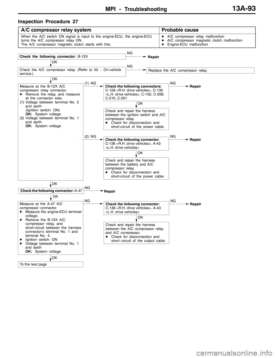
Inspection Procedure 27
A/C compressor relay system
Probable cause
When the A/C switch ON signal is input to the engine-ECU, the engine-ECU
turns the A/C compressor relay ON.
The A/C compressor magnetic clutch starts with this.DA/C compressor relay malfunction
DA/C compressor magnetic clutch malfunction
DEngine-ECU malfunction
OK
(2) NGCheck the following connector:
C-136
Check and repair the harness
between the battery and A/C
compressor relay.
DCheck for disconnection and
short-circuit of the power cable.
OK
Check the A/C compressor relay. (Refer to 55 - On-vehicle
service.)NGReplace the A/C compressor relay.
Check the following connector:B-12XNG
Repair
OK
OK
Measure at the B-12X A/C
compressor relay connector.
DRemove the relay, and measure
at the connector side.
(1) Voltage between terminal No. 2
and earth
(Ignition switch: ON)
OK:System voltage
(2) Voltage between terminal No. 1
and earth
OK:System voltage(1) NGCheck the following connectors:
C-128
C-210, C-201NG
OK
Check and repair the harness
between the ignition switch and A/C
compressor relay.
DCheck for disconnection and
short-circuit of the power cable.Repair
OKNG
Measure at the A-47 A/C
compressor connector.
DMeasure the engine-ECU terminal
voltage.
DRemove the B-12X A/C
compressor relay, and
short-circuit between the harness
connector’s terminal No. 1 and
terminal No. 4.
DIgnition switch: ON
DVoltage between terminal No. 1
and earth
OK:System voltage
To the next pageRepair
NG
OK
Check the following connector:A-47
Repair
OK
Check the following connector:
C-136
Check and repair the harness
between the A/C compressor relay
and A/C compressor.
DCheck for disconnection and
short - circuit of the output cable.Repair
Page 626 of 1449

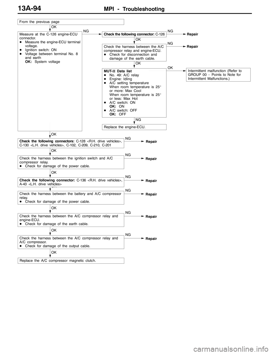
MPI -Troubleshooting13A-94
OK
OK
Check the harness between the battery and A/C compressor
relay.
DCheck for damage of the power cable.NG
Repair
OK
Check the following connector:C-136
A-43
Repair
NG
Replace the engine-ECU.
NG
Repair
OK
OKMUT-IIData list
DNo. 49: A/C relay
DEngine: Idling
DA/C setting temperature
When room temperature is 25_
or more: Max Cool
When room temperature is 25_
or less: Max Hot
DA/C switch: ON
OK:ON
DA/C switch: OFF
OK:OFF
OK
OK
Measure at the C-126 engine-ECU
connector.
DMeasure the engine-ECU terminal
voltage.
DIgnition switch: ON
DVoltage between terminal No. 8
and earth
OK:System voltageNGCheck the following connector:C-126NG
OK
Check the harness between the A/C
compressor relay and engine-ECU.
DCheck for disconnection and
damage of the earth cable.Repair
OK
Check the harness between the ignition switch and A/C
compressor relay.
DCheck for damage of the power cable.NG
Check the following connectors:C-128
C-130
From the previous page
Intermittent malfunction (Refer to
GROUP 00 - Points to Note for
Intermittent Malfunctions.)
Repair NG
OK
Check the harness between the A/C compressor relay and
engine-ECU.
DCheck for damage of the earth cable.NG
Repair
OK
Check the harness between the A/C compressor relay and
A/C compressor.
DCheck for damage of the output cable.NG
Repair
Replace the A/C compressor magnetic clutch.
Page 637 of 1449

MPI -Troubleshooting13A-105
Item
No.Reference
page Inspection
procedure
No. Normal condition Inspection contents Inspection
item
44Ignition ad-
vanceDEngine: After
having warmed
up
DTiming lamp is
set(Thetiming
Engine: Idle operation0-13_BTDC--
set.(Thetiming
lamp is set in
order to check
actual ignition
timing.)
2,500 r/min20 - 40_BTDC
45Idle speed
control
(stepper)
motor
position*
3
DEngine coolant
temperature:
80 - 90_C
DLamps, electric
cooling fan and
all accessories:
OFF
DTransmission:
A/C switch: OFF2 - 25 STEP--
DTransmission:
Neutral
DEngine: Idle
operation
DWhen A/C switch
is ON, A/C
compressor
should be operat-
ing
A/C switch: OFF→ONIncreases by 10 -
70 steps
49A/C relayEngine: After having
warmed up/Engine is
idlingA/C switch: OFFOFF (Compressor
clutch is not oper-
ating)Procedure
No. 2713A-92
A/C switch: ONON (Compressor
clutch is operat-
ing)
59Oxygen
sensor
(rear)Engine: After having
warmed-upWhen engine is sud-
denly raced0 and 600 - 1,000
mV alternate.Code No.
P013613A-27
81LLearned
valueEngine: After having warmed up, running with no
load at 2,500 r/min. (During air/fuel ratio
feedback control)- 12.5 - 12.5%--
82LFeedbackEngine: After having warmed up, running with no
load at 2,500 r/min. (During air/fuel ratio
feedback control)- 20 - 20%--
87LEngine
load
Engine: After having
warmedup
Idle operation15 - 35%--
loadwarmedup
2,500 r/min15 - 35%--