Page 851 of 1449

MANUAL TRANSMISSION - On-vehicle Service22A-43
4. Set the gear to the 2nd gear or above, operate the MUT-II,
and check from the service data (Item No.09) that the
wheel speed is within 10 km/h to 20 km/h.
NOTE
(1) Set the steering wheel to the neutral position
(2) The ACD may continue operating (operation sounds
can be heard) when the steering wheel is steered,
this is not a system fault. In this case, set the steering
wheel to the neutral position, and perform the following
operations to stop the ACD.
DRelease the clutch.
DSet the gear to “N”.
DStop the engine
5. Perform the MUT-IIactuator test (Item No.05), and forcibly
drive the transfer.
NOTE
(1) The actuator test (Item No. 05: ACD Operation Check
Mode) is performed for 1 minute, after which it will
be cleared automatically. Drive can also be cleared
during forced driving using the clear key of the MUT-II.
(2) If the hydraulic unit function has been stopped by
fail-safe, the transfer cannot be forcibly driven.
6. Check that the front and rear wheel speeds satisfy the
following in the MUT-IIactuator test (Item No.05).
The front wheel will be faster than the back wheels by
more than 2 km/h.
NOTE
If the above are not satisfied, check the oil pressure as
the system may be faulty.
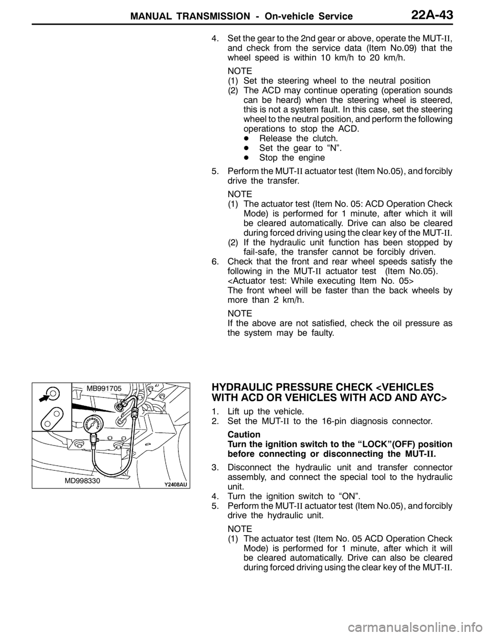
HYDRAULIC PRESSURE CHECK
WITH ACD OR VEHICLES WITH ACD AND AYC>
1. Lift up the vehicle.
2. Set the MUT-IIto the 16-pin diagnosis connector.
Caution
Turn the ignition switch to the “LOCK”(OFF) position
before connecting or disconnecting the MUT-II.
3. Disconnect the hydraulic unit and transfer connector
assembly, and connect the special tool to the hydraulic
unit.
4. Turn the ignition switch to “ON”.
5. Perform the MUT-IIactuator test (Item No.05), and forcibly
drive the hydraulic unit.
NOTE
(1) The actuator test (Item No. 05 ACD Operation Check
Mode) is performed for 1 minute, after which it will
be cleared automatically. Drive can also be cleared
during forced driving using the clear key of the MUT-II.
MD998330
MB991705
Page 860 of 1449
MANUAL TRANSMISSION - Transmission Assembly22A-52
TRANSMISSION ASSEMBLY
REMOVAL AND INSTALLATION
Pre-removal and Post-installation Operation
DTransfer Assembly Removal and Installation (Refer to P.22A-49.)
DStarter Motor Removal and Installation (Refer to GROUP 16.)
DAir Cleaner Bracket Removal and Installation (Refer to GROUP 15 - Air Cleaner.)
DRear Roll Rod Assembly and Rear Roll Rod Bracket , Rear Roll Mount
Removal and Installation (Refer to GROUP 32 - Engine Roll Stopper.)
1
2
3 45
5 6
7
18±3 N·m18±3 N·m
18±3 N·m
70±10 N·m
Removal steps
1. Transmission harness clamp
2. Back-up lamp switch connector
connection
3. Vehicle speed sensor connector
connection
4. Clutch release cylinder and clutch
oil pipe5. Snap pin
6. Shift cable and select cable as-
sembly connection
7. Rear roll mount bracket
AA"DEngine and transmission
assembly supporting
Page 861 of 1449
MANUAL TRANSMISSION - Transmission Assembly22A-53
10
10 11
9
1412 88
13
48±5 N·m
48±5 N·m
48±5 N·m
48±5 N·m
9.0±1.0 N·m
26±5 N·m
82±7 N·m*
47±7 N·m*
8. Transmission assembly upper part
coupling bolts
AA"9. Transmission mount assembly
"AA10. Transmission mount stopper
11. Transmission mount bracket
AB"DEngine assembly supporting
AC"DClutch release bearing connection
12. Bell housing cover13. Transmission assembly lower part
coupling bolts
14. Transmission assembly
Caution
*: Indicates parts which should be initially tightened,
and then fully tightened after placing the vehicle
horizontally and loading the full weight of the engine
on the vehicle body.
REMOVAL SERVICE POINTS
AA"ENGINE AND TRANSMISSION ASSEMBLY
SUPPORTING/TRANSMISSION MOUNT
ASSEMBLY REMOVAL
While supporting the engine and transmission assembly with
a garage jack, remove the transmission mount assembly.Engine and transmission
assembly
Garage jack
Page 862 of 1449

MANUAL TRANSMISSION - Transmission Assembly22A-54
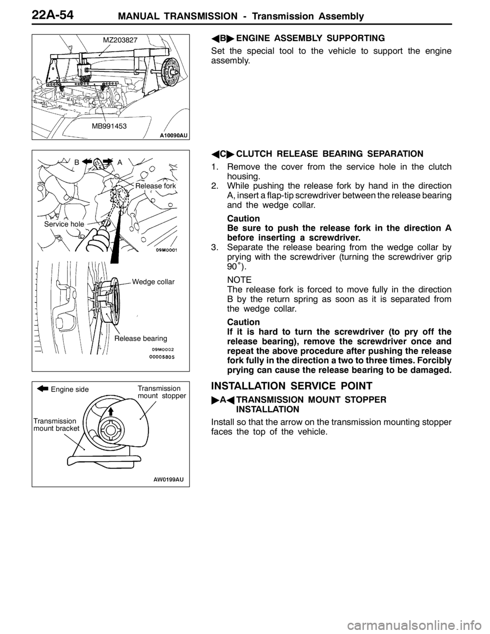
AB"ENGINE ASSEMBLY SUPPORTING
Set the special tool to the vehicle to support the engine
assembly.
AC"CLUTCH RELEASE BEARING SEPARATION
1. Remove the cover from the service hole in the clutch
housing.
2. While pushing the release fork by hand in the direction
A, insert a flap-tip screwdriver between the release bearing
and the wedge collar.
Caution
Be sure to push the release fork in the direction A
before inserting a screwdriver.
3. Separate the release bearing from the wedge collar by
prying with the screwdriver (turning the screwdriver grip
90˚).
NOTE
The release fork is forced to move fully in the direction
B by the return spring as soon as it is separated from
the wedge collar.
Caution
If it is hard to turn the screwdriver (to pry off the
release bearing), remove the screwdriver once and
repeat the above procedure after pushing the release
fork fully in the direction a two to three times. Forcibly
prying can cause the release bearing to be damaged.
INSTALLATION SERVICE POINT
"AATRANSMISSION MOUNT STOPPER
INSTALLATION
Install so that the arrow on the transmission mounting stopper
faces the top of the vehicle.
MZ203827
MB991453
BA
Service hole
Release fork
Wedge collar
Release bearing
Transmission
mount bracket
Transmission
mount stopper Engine side
Page 867 of 1449
22B-1
MANUAL
TRANSMISSION
OVERHAUL
CONTENTS
GENERAL DESCRIPTION 2...................
SPECIFICATIONS 6..........................
SERVICE SPECIFICATIONS 6.................
SEALANTS 7................................
LUBRICANTS 8..............................
SNAP RINGS, SPACERS AND THRUST
PLATES FOR ADJUSTMENT 9................
TIGHTENING TORQUE 11....................
SPECIAL TOOLS 12..........................
TRANSMISSION 15...........................
INPUT SHAFT 22............................OUTPUT SHAFT 29..........................
REVERSE IDLER GEAR 37...................
SPEEDOMETER GEAR 38....................
SELECT LEVER 39...........................
CONTROL HOUSING 40......................
CLUTCH HOUSING 43........................
TRANSMISSION CASE 46....................
CENTER DIFFERENTIAL 48..................
TRANSFER 51...............................
Page 873 of 1449

MANUAL TRANSMISSION OVERHAUL -Sealants22B-7
SEALANTS
TRANSMISSION
ItemsSpecified sealants
Clutch housing and transmission case contact surfaceMITSUBISHI genuine sealant Part
No MD997740orequivalent
Control housing and transmission case contact surface
No.MD997740or equivalent
Under cover and transmission case contact surface
Air breather3M SUPER WEATHERSTRIP No.8001 or
equivalent
Center differential drive gear bolt3M STUD Locking No.4170 or equivalent
FORM-IN-PLACE GASKET (FIPG)
FIPG is used for several members of this transmission. With this gasket, caution is required to the application
amount, application procedure and state of the application surface so that the performance is sufficiently
attained.
If sufficient gasket is not applied, leaks could occur, and if too much is applied, the gasket could protrude
and plug or restrict the oil flow passage. Thus, to prevent leaks from the joined sections, it is absolutely
necessary to evenly apply the correct amount.
DISASSEMBLY
The parts assembled with FIPG can be easily disassembled without special means. However, in some
cases, the sealant on the contact surfaces must be broken by lightly tapping with a wood hammer or
similar tool.
Washing the gasket surface
Completely remove all matters adhered on the contact surfaces with a gasket scraper. Confirm that the
FIPG application surface is smooth. There must be no grease or foreign matter on the contact surfaces.
Always remove the old FIPG that has entered the mounting holes and screw holes.
APPLICATION PROCEDURES
Apply an even coat of FIPG within the predetermined radius (1.5±0.3 mm). Completely cover the areas
around the mounting holds. The FIPG can be wiped off if it has not hardened. Install at the set position
while the FIPG is still wet (within 10 minutes). When installing, make sure that the FIPG does not get
on areas other than the required areas. After installing, do not subject the application areas to oil or
water or start operation until the FIPG has sufficiently hardened (approx. one hour).
The FIPG application procedures differ according to the member, so follow the procedures given in this
manual and apply the FIPG.
Page 877 of 1449
MANUAL TRANSMISSION OVERHAUL -Tightening Torque22B-11
TIGHTENING TORQUE
TRANSMISSION
ItemsTightening torque N•m
Under cover mounting bolt6.9±1
Interlock plate bolt30±3
Clutch housing and transmission case tightening bolt44±5
Clutch release bearing retainer mounting bolt9.8±2
Control housing mounting bolt18±3
Shift cable bracket mounting bolt18±3
Speedometer gear mounting bolt3.9±1
Stopper bracket mounting bolt18±3
Select lever mounting bolt18±3
Select lever mounting nut11±1
Center differential drive gear mounting bolt132±5
Backup light switch32±2
Poppet spring32±2
Reverse idler gear shaft mounting bolt48±5
Roll stopper bracket mounting bolt69±9
TRANSFER
ItemsTightening torque N•m
Transfer cover mounting bolt23±3
Transmission and transfer tightening bolt69±9
Page 883 of 1449
MANUAL TRANSMISSION OVERHAUL -Transmission22B-17
29
Apply gear oil on
all sliding sections
before installing.
36
3230
28
35
38 37 3927
34 33
31
Disassembly steps
"CA27. Spring pin
28. 1st-2nd speed shift rail
29. 1st-2nd speed shift fork
"CA30. Spring pin
AA""CA31. Spring pin
AB""BA32. 3rd-4th speed shift rail
AB""BA33. 3rd-4th speed shift forkAB""BA34. 5th-reverse speed shift rail
AB""BA35. 5th-reverse speed shift fork
AC""AA36. Center differential
AC""AA37. Output shaft
AC""AA38. Input shaft
39. Clutch housing