2007 MITSUBISHI LANCER EVOLUTION clutch
[x] Cancel search: clutchPage 998 of 1449

REAR AXLE -Differential Carrier
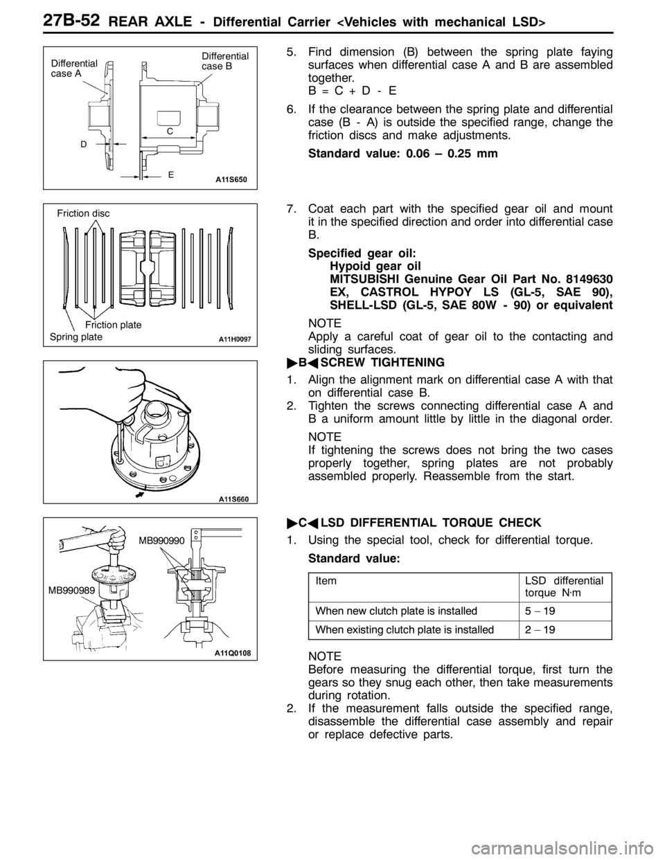
5. Find dimension (B) between the spring plate faying
surfaces when differential case A and B are assembled
together.
B=C+D - E
6. If the clearance between the spring plate and differential
case (B - A) is outside the specified range, change the
friction discs and make adjustments.
Standard value: 0.06 – 0.25 mm
7. Coat each part with the specified gear oil and mount
it in the specified direction and order into differential case
B.
Specified gear oil:
Hypoid gear oil
MITSUBISHI Genuine Gear Oil Part No. 8149630
EX, CASTROL HYPOY LS (GL-5, SAE 90),
SHELL-LSD (GL-5, SAE 80W - 90) or equivalent
NOTE
Apply a careful coat of gear oil to the contacting and
sliding surfaces.
"BASCREW TIGHTENING
1. Align the alignment mark on differential case A with that
on differential case B.
2. Tighten the screws connecting differential case A and
B a uniform amount little by little in the diagonal order.
NOTE
If tightening the screws does not bring the two cases
properly together, spring plates are not probably
assembled properly. Reassemble from the start.
"CALSD DIFFERENTIAL TORQUE CHECK
1. Using the special tool, check for differential torque.
Standard value:
ItemLSD differential
torque N·m
Whennewclutchplateisinstalled5–19When new clutchplateisinstalled5–19
Whenexistingclutchplateisinstalled2–19When existing clutchplateisinstalled2–19
NOTE
Before measuring the differential torque, first turn the
gears so they snug each other, then take measurements
during rotation.
2. If the measurement falls outside the specified range,
disassemble the differential case assembly and repair
or replace defective parts.
D
Differential
case A
E C
Differential
case B
Spring plateFriction plate Friction disc
MB990990
MB990989
Page 1060 of 1449

BASIC BRAKE SYSTEM -ProportioningValve,MasterCylinder
and Brake Booster35A-18
Master cylinder removal steps
1. Clutch hose connection
2. Brake fluid level sensor connector
3. Reservoir cap assembly
4. Brake fluid level sensor
5. Brake pipe connection
6. Proportioning valve
7. O ring
8. Master cylinder
Proportioning valve removal steps
5. Brake pipe connection
6. Proportioning valve
7. O ring
Brake booster removal steps
1. Clutch hose connection
2. Brake fluid level sensor connector5. Brake pipe connection
8. Master cylinder
"BADPush rod protrusion amount check and
adjustment
"AA9. Vacuum hose
(With built-in check valve)
10. Snap pin
11. Pin assembly
12. Clevis
DRemove A/C liquid pipe B
from the
retaining clip.(Refer to GROUP 55A
- Refrigerant Line.)
13. Brake booster
14. Sealer
Fitting removal steps
"AA9. Vacuum hose
(With built-in check valve)
15. Fitting
INSTALLATION SERVICE POINTS
"AAVACUUM HOSE CONNECTION
Insert the vacuum hose to the brake booster with its paint
mark facing upward, and then secure the hose by using the
hose clip.
"BAPUSH ROD PROTRUSION AMOUNT CHECK AND
ADJUSTMENT
1. Measure dimension (A).
Standard value (A) : 8.98 - 9.23 mm
NOTE
When a negative pressure of 66.7 kPa is applied to the
brake booster, the push rod should protrude 10.27 – 10.53
mm.
Block gauge Measuring distance A
A
Page 1403 of 1449

55-1
HEATER, AIR
CONDITIONER AND
VENTILATION
CONTENTS
SERVICE SPECIFICATIONS 2.................
LUBRICANTS 2..............................
SPECIAL TOOLS 2...........................
TROUBLESHOOTING 3.......................
ON-VEHICLE SERVICE 14....................
Refrigerant Level Test through Performance Test 14.
Magnetic Clutch Test 14.........................
Receiver Drier Test 14..........................
Compressor Drive Belt Adjustment 15.............
Dual Pressure Switch Check 15..................
Charging 16...................................
Correcting Low Refrigerant Level in case the Service
can used 18...................................
Discharging System 19..........................
Refilling of Oil in the A/C System 19...............
Performance Test 20............................
Refrigerant Leak Repair 21......................
Blower Relay Continuity Check 22................
A/C Compressor Relay Continuity Check 22........Condenser Fan Relay (LO) Check 23.............
Condenser Fan Relay (HI) Check 23..............
Idle-up Operation Check 24.....................
HEATER CONTROL ASSEMBLY (A/C-ECU)
AND A/C SWITCH 25........................
HEATER UNIT AND BLOWER ASSEMBLY 28.
REGISTOR, BLOWER MOTOR AND
INSIDE/OUTSIDE AIR CHANGE OVER
DAMPER MOTOR 32.........................
EVAPORATOR AND AIR THERMO SENSOR
34 ...........................................
COMPRESSOR 36............................
CONDENSER ASSEMBLY AND CONDENSER
FAN ASSEMBLY 40...........................
REFRIGERANT LINES 42.....................
DUCTS 44...................................
VENTILATION 45.............................
Page 1405 of 1449

HEATER, AIR CONDITIONER AND VENTILATION-Troubleshooting55-3
TROUBLESHOOTING
BASIC FLOW OF TROUBLESHOOTING
Refer to Group 00 – How to Use Troubleshooting/Inspection Service Points.
INSPECTION CHART FOR TROUBLE SYMPTOMS
Trouble symptomInspection procedureReference page
Air conditioner not working at all155 - 3
Blower motor not working255 - 4
Air cannot be switched between inside and outside355 - 5
Rear defogger not working455-6
Cold air not coming out from the air outlet555 - 7
Magnet clutch not working normally655 - 8
Condenser fan not working at all755-9
Condenser fan not working only for LO855-10
Condenser fan not working only for HI955-11
INSPECTION PROCEDURE FOR TROUBLE SYMPTOM
Inspection procedure 1
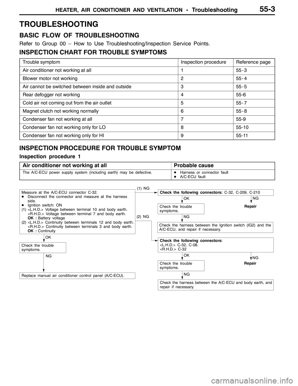
Air conditioner not working at all
Probable cause
The A/C-ECU power supply system (including earth) may be defective.DHarness or connector fault
DA/C-ECU fault
NG
Repair
NG
Check the harness between the Ignition switch (IG2) and the
A/C-ECU, and repair if necessary.
NG
Repair
NG
Check the harness between the A/C-ECU and body earth, and
repair if necessary.
NG
Replace manual air conditioner control panel (A/C-ECU).
OK
Check the trouble
symptoms.
Check the following connectors:
(2) NG
OK
Check the trouble
symptoms.
Measure at the A/C-ECU connector C-32.
DDisconnect the connector and measure at the harness
side.
DIgnition switch: ON
(1)
OK :Battery voltage
(2)
OK :Continuity(1) NGCheck the following connectors:C-32, C-209, C-210
OK
Check the trouble
symptoms.
Page 1409 of 1449

HEATER, AIR CONDITIONER AND VENTILATION-Troubleshooting55-7
Inspection procedure 5
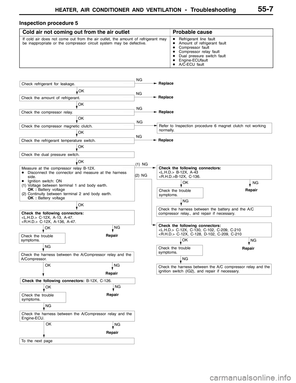
Cold air not coming out from the air outlet
Probable cause
If cold air does not come out from the air outlet, the amount of refrigerant may
be inappropriate or the compressor circuit system may be defective.DRefrigerant line fault
DAmount of refrigerant fault
DCompressor fault
DCompressor relay fault
DDual pressure switch fault
DEngine-ECUfault
DA/C-ECU fault
OK
NG
Repair
NG
Check the harness between the A/C compressor relay and the
ignition switch (IG2), and repair if necessary.
OK
Check the trouble
symptoms.
Check the following connectors:
Repair
Check the following connectors:
OK
OK
Check the trouble
symptoms.
NG
OK
NG
Replace
OK
OK
OK
NG
Check the harness between the battery and the A/C
compressor relay., and repair if necessary.
OK
Check the trouble
symptoms.
Check the following connectors:
RepairNG
(2) NG
OK
Check the dual pressure switch.
OK
NG
Repair
Check the harness between the A/Compressor relay and the
A/Compressor.
NG
Repair
Check the following connectors:B-12X, C-126.
OK
Check the trouble
symptoms.
NG
OKNG
Repair
Check the harness between the A/Compressor relay and the
Engine-ECU.
To the next page
Check refrigerant for leakage.
NG
Replace
NG
Replace
NG
NG
Replace
Check the amount of refrigerant.
Check the compressor relay.
Check the compressor magnetic clutch.
Check the refrigerant temperature switch.
Measure at the compressor relay B-12X.
DDisconnect the connector and measure at the harness
side.
DIgnition switch: ON
(1) Voltage between terminal 1 and body earth.
OK :Battery voltage
(2) Continuity between terminal 2 and body earth.
OK :Battery voltage
Refer to Inspection procedure 6 magnet clutch not working
normally.
Page 1410 of 1449

HEATER, AIR CONDITIONER AND VENTILATION-Troubleshooting55-8
Repair
Repair
NG
Replace the A/C-ECU .
Replace the Engine-ECU .
NG
Repair
Check the following connectors:
OK
Check the trouble
symptoms.
NG
OKNG
Check the harness between the dual pressure switch and the
Engine-ECU.
Check the following connectors:C-32, C-111, A-36.
OK
NG
OKNG
Check the harness between the dual pressure switch and the
A/C-ECU.
From the previous page
Check the trouble
symptoms.RepairNG
Inspection procedure 6
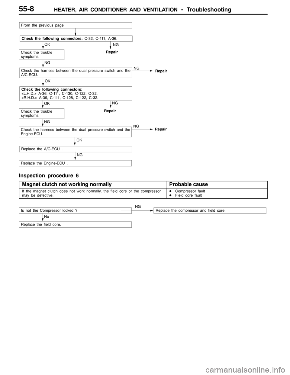
Magnet clutch not working normally
Probable cause
If the magnet clutch does not work normally, the field core or the compressor
may be defective.DCompressor fault
DField core fault
Replace the field core.
Is not the Compressor locked ?NGReplace the compressor and field core.
No
Page 1416 of 1449

HEATER, AIR CONDITIONER AND VENTILATION–On-vehicle Service55-14
ON-VEHICLE SERVICE
REFRIGERANT LEVEL TEST THROUGH
PERFORMANCE TEST
1. Start the engine.
2. Turn on the A/C switch, and set the A/C control to MAX.
COOL.
3. Adjust the engine speed to 1,500 r/min.
4. Check the refrigerant level (bubble state) through the
sight glass.
ItemState
Insufficient refriger-
antMany bubbles are seen. If refrigerant
is extremely low, it appears white.
Sufficient or excess
refrigerantNo bubbles are seen
NOTE
1. If insufficient, replenish the refrigerant as follows.
a) Replenish until bubbles disappear from the sight
glass.
b) After the bubbles disappear from the sight glass,
replenish 100g of refrigerant.
2. If excessive, replenish the refrigerant as follows.
a) Drain the refrigerant until bubbles can be seen
through the sight glass.
b) Replenish until bubbles disappear from the sight
glass.
c) After the bubbles disappear from the sight glass,
replenish 100g of refrigerant.
MAGNETIC CLUTCH TEST
1. Disconnect the connector to the magnetic clutch.
2. Connect battery (+) voltage directly to the connector for
the magnetic clutch.
3. If the magnetic clutch is normal, there will be ”click”. If
the pulley and armature do not make contact (’click’),
there is a malfunction.
RECEIVER DRIER TEST
Operate the unit and check the piping temperature by touching
the receiver drier outlet and inlet.
If there is a difference in the temperatures, the receiver drier
is restricted.
Replace the receiver drier.
Insufficient
refrigerantSufficient or excess
refrigerant
Bubbles
Page 1422 of 1449

HEATER, AIR CONDITIONER AND VENTILATION–On-vehicle Service HEATER, AIR CONDITIONER AND VENTILATION–On-vehicle Service55-20
PERFORMANCE TEST
1. The vehicles to be tested should be in a place that is
not in direct sunlight.
2. Close the high and low-pressure valve of the gauge
manifold.
3. Connect the charging hose (blue) to the low-pressure
valve and connect the charging hose (red) to the
high-pressure valve of the gauge manifold.
4. Install the quick joint (for low-pressure) to the charging
hose (blue), and connect the quick joint (for high-pressure)
to the charging hose (red).
5. Connect the quick joint (for low-pressure) to the
low-pressure service valve and connect the quick joint
(for high-pressure) to the high-pressure service valve.
NOTE
The high-pressure service valve is on liquid pipe A and the
low-pressure service valve is on the suction hose.
Caution
To connect the quick joint, press section “A” firmly
against the service valve until a click is heard.
When connecting, run your hand along the hose while
pressing to ensure that there are no bends in the
hose.
6. Start the engine.
7. Set the controls to the A/C as follows:
DA/C switch: A/C - ON position
DMode selection: Face position
DTemperature control: Max. cooling position
DAir selection: Recirculation position
DBlower switch: HI (Fast) position
8. Keep engine speed to idling speed with A/C clutch engaged.
9. Engine should be warmed up with doors and all windows
opened.
10. Insert a thermometer in the center A/C outlet and operate
the engine for 20 minutes.
11. Note the discharge air temperature.
NOTE
If the clutch cycles, take the reading before the clutch
disengages.
Performance Temperature Chart
Garage ambient temperature_C20253035
Discharge air temperature_C8-1112 - 1617 - 2122.5 - 27.5
Compressor high-pressure kPa740 - 840950 - 1,0501,160 - 1,3001,360 - 1,550
Compressor low-pressure kPa150 - 190190 - 240240 - 300300 - 375
Low-pressure valve
High-pressure valve
Gauge manifold
Charging
hose (red)
Charging
hose (blue)
Adaptor
valve (for low
pressure)Sleeve
Adaptor valve
(for high pressure)
Low-
pressure
service
valveHigh-
pressure
service
valveA
Thermometer