2007 MITSUBISHI LANCER EVOLUTION transmission oil
[x] Cancel search: transmission oilPage 112 of 1449

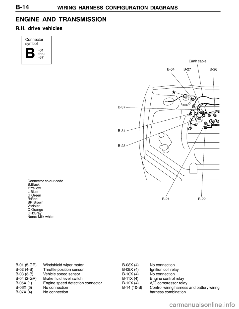
WIRING HARNESS CONFIGURATION DIAGRAMS
Connector
symbol
-01
thru
-37
B
Earth cable
B-27B-26B-04
B-22B-21
B-37
B-34
B-23
Connector colour code
B:Black
Y:Yellow
L:Blue
G:Green
R:Red
BR:Brown
V:Violet
O:Orange
GR:Gray
None: Milk white
B-14
ENGINE AND TRANSMISSION
R.H. drive vehicles
B-01 (5-GR) Windshield wiper motor
B-02 (4-B) Throttle position sensor
B-03 (3-B) Vehicle speed sensor
B-04 (2-GR) Brake fluid level switch
B-05X (1) Engine speed detection connector
B-06X (5) No connection
B-07X (4) No connectionB-08X (4) No connection
B-09X (4) Ignition coil relay
B-10X (4) No connection
B-11X (4) Engine control relay
B-12X (4) A/C compressor relay
B-14 (10-B) Control wiring harness and battery wiring
harness combination
Page 382 of 1449

GENERAL -How to Use This Manual00-4
EXPLANATION OF MANUAL CONTENTS
Indicates procedures to be performed
before the work in that section is started,
and procedures to be performed after
the work in that section is finished.
Indicates (by symbols) where lubrica-
tion is necessary.
Maintenance and Servicing Procedures
The numbers provided within the diagram indi-
cate the sequence for maintenance and servic-
ing procedures.
DRemoval steps:
The part designation number corresponds
to the number in the illustration to indicate
removal steps.
DDisassembly steps:
The part designation number corresponds
to the number in the illustration to indicate
disassembly steps.DInstallation steps:
Specified in case installation is impossible
in reverse order of removal steps. Omitted
if installation is possible in reverse order of
removal steps.
DReassembly steps:
Specified in case reassembly is impossible
in reverse order of disassembly steps.
Omitted if reassembly is possible in reverse
order of disassembly steps.
Classifications of Major Maintenance/Service Points
When there are major points relative to maintenance and servicing procedures
(such as essential maintenance and service points, maintenance and service stan-
dard values, information regarding the use of special tools, etc.), these are ar-
ranged together as major maintenance and service points and explained in detail.
AA": Indicates that there are essential points for removal or disassembly.
"AA: Indicates that there are essential points for installation or reassembly.
Symbols for Lubrication, Sealants and Adhesives
Information concerning the locations for lubrica-
tion and for application of sealants and adhe-
sives is provided, by using symbols, in the dia-
gram of component parts or on the page follow-
ing the component parts page, and explained.: Grease
(multipurpose grease unless there is
a brand or type specified)
: Sealant or adhesive
: Brake fluid or automatic transmission fluid
: Engine oil, gear oil or air conditioner
compressor oil
: Adhesive tape or butyl rubber tape
Component Diagram
A diagram of the component parts is
provided near the front of each section
in order to give a reader a better under-
standing of the installed condition of
component parts.
Page 432 of 1449

ENGINE -Crankshaft Oil Seal11A-26
CRANKSHAFT OIL SEAL
REMOVAL AND INSTALLATION
Caution
If the vehicle is equipped with the Brembo disc brake, during maintenance, take care not to contact
the parts or tools to the caliper because the paint of caliper will be scratched.
1 2
34 5
6
Engine oil
(at the lip)
(at the lip)
3
6
132±5 N·m
Crankshaft Front Oil Seal Removal
Steps
DTiming belt and timing belt B
(Refer to P.11A-34.)
"DA1. Crankshaft sprocket B
2. Key
"CA3. Crankshaft front oil sealCrankshaft Rear Oil Seal Removal
Steps
DTransfer assembly
(Refer to GROUP 22A.)
DTransmission assembly
(Refer to GROUP 22A.)
DClutch cover, disc
AA""BA4. Flywheel bolt
5. Flywheel
"AA6. Crankshaft rear oil seal
Page 451 of 1449

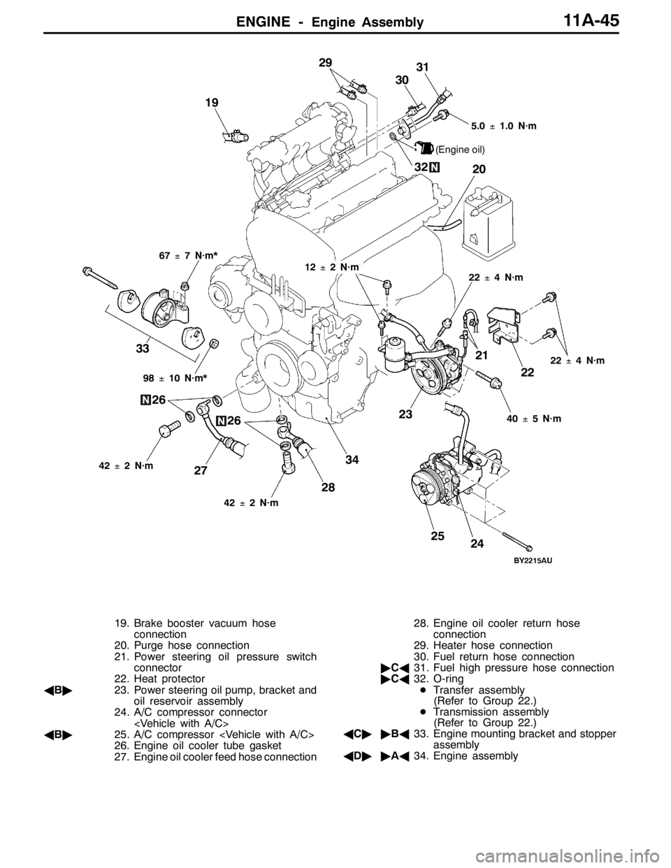
ENGINE -Engine Assembly11A-45
67±7 N·m*
23 33
24 29
3031
32
2722
98±10 N·m*5.0±1.0 N·m
(Engine oil)
20
21 19
25
42±2 N·m22±4 N·m
40±5 N·m
42±2 N·m
26
26
2834
22±4 N·m12±2 N·m
19. Brake booster vacuum hose
connection
20. Purge hose connection
21. Power steering oil pressure switch
connector
22. Heat protector
AB"23. Power steering oil pump, bracket and
oil reservoir assembly
24. A/C compressor connector
AB"25. A/C compressor
26. Engine oil cooler tube gasket
27. Engine oil cooler feed hose connection28. Engine oil cooler return hose
connection
29. Heater hose connection
30. Fuel return hose connection
"CA31. Fuel high pressure hose connection
"CA32. O-ring
DTransfer assembly
(Refer to Group 22.)
DTransmission assembly
(Refer to Group 22.)
AC""BA33. Engine mounting bracket and stopper
assembly
AD""AA34. Engine assembly
Page 452 of 1449

ENGINE -Engine Assembly11A-46
REMOVAL SERVICE POINTS
AA"DRIVE BELT REMOVAL
Due to the adoption of the Serpentine drive system with the
auto-tensioner, the following operation is required:
1. Insert the 12.7sq. spinner handle into the tool hole of
the auto-tensioner and rotate it counterclockwise until
the auto-tensioner reaches to the stopper.
2. Align hole A with hole B for fixing by inserting the L
shaped-hexagon wrench, then remove the drive belt.
Caution
When the drive belt is reused, use a chalk to indicate
an arrow of rotation direction on the back of the belt
so that it can be re-assembled in the same direction
as before.
AB"POWER STEERING OIL PUMP, BRACKET AND
OIL RESERVOIR ASSEMBLY / A/C COMPRESSOR
REMOVAL
Remove the power steering oil pump, bracket, oil reservoir
and A/C compressor with the hose attached from the bracket.
NOTE
Tie the removed oil pump and A/C compressor with a rope
and set aside where they cannot hinder the removal of the
engine assembly.
AC"ENGINE MOUNTING BRACKET AND STOPPER
ASSEMBLY REMOVAL
1. Support the engine with a garage jack.
2. Remove special tool (MZ203827).
(Tool used for removal of transmission assembly)
3. Hold the engine assembly with a chain block.
4. Support the engine oil pan with a garage jack via a block
of wood cut without applying the weight of the engine
and remove the engine mounting bracket and stopper
assembly.
Bore A
L-shaped
hexagon
wrench
Bore B
MZ203827
MB991453
MB991453
Page 453 of 1449

ENGINE -Engine Assembly11A-47
AD"ENGINE ASSEMBLY REMOVAL
After checking that all the cables, hoses, and harness
connectors have been disconnected, lift the engine with a
chain block slowly and remove the engine assembly located
at the upper engine room.
INSTALLATION SERVICE POINTS
"AAENGINE ASSEMBLY INSTALLATION
Install the engine assembly while checking that none of cables,
hoses, or harness connectors, etc. has been engaged.
"BAENGINE MOUNTING BRACKET AND STOPPER
ASSEMBLY INSTALLATION
1. Support the engine oil pan with a garage jack via a block
of wood cut adjusting the engine position and install the
engine mounting bracket and stopper assembly. Position
the engine mounting stopper so that a mark indicated
by an arrow can face the direction shown in the illustration.
2. Support engine with garage jack.
3. Remove the chain block and hold the engine assembly
with the special tool.(Tool used for removal of transmission
assembly)
"CAO-RING/FUEL HIGH PRESSURE HOSE
INSTALLATION
1. Apply small quantity of new engine oil on O-ring.
Caution
Do not let engine oil get into the delivery pipe.
2. Install the fuel high pressure pipe to the delivery pipe
rotating in both directions without damaging the O-ring
and check that it rotates smoothly.
3. In case of not rotating smoothly, remove the fuel high
pressure hose and insert it to the delivery pipe again
after checking damage of the O-ring since there is a
possibility of O-ring engagement.
4. Tighten fuel high pressure hose mounting bolt to the
specified torque.
Tightening Torque: 5.0±1.0 N·m
Engine mounting stopper
Engine side
Page 758 of 1449

ENGINE ELECTRICAL -Ignition System16-26
IGNITION SYSTEM
GENERAL INFORMATION
This system is equipped with two ignition coils (A
and B) with built-in power transistors for the No.
1 and No. 4 cylinders and the No. 2 and No. 3
cylinders respectively.
Interruption of the primary current flowing in the
primary side of ignition coil A generates a high
voltage in the secondary side of ignition coil A.
The high voltage thus generated is applied to the
spark plugs of No. 1 and No. 4 cylinders to generate
sparks. At the time that the sparks are generated
at both spark plugs, if one cylinder is at the
compression stroke, the other cylinder is at the
exhaust stroke, so that ignition of the compressed
air/fuel mixture occurs only for the cylinder which
is at the compression stroke.
In the same way, when the primary current flowing
in ignition coil B is interrupted, the high voltage
thus generated is applied to the spark plugs of
No. 2 and No. 3 cylinders.
The Engine-ECU turns the two power transistors
inside the ignition coils alternately on and off. Thiscauses the primary currents in the ignition coils
to be alternately interrupted and allowed to flow
to fire the cylinders in the order 1-3-4-2.
The Engine-ECU determines which ignition coil
should be controlled by means of the signals from
the camshaft position sensor which is incorporated
in the camshaft and from the crank angle sensor
which is incorporated in the crankshaft. It also
detects the crankshaft position in order to provide
ignition at the most appropriate timing in response
to the engine operation conditions. It also detects
the crankshaft position in order to provide ignition
at the most appropriate timing in response to the
engine operation conditions.
When the engine is cold or operated at high
altitudes, the ignition timing is slightly advanced
to provide optimum performance.
When the automatic transmission shifts gears, the
ignition timing is also retarded in order to reduce
output torque, thereby alleviating shifting shocks.
SYSTEM DIAGRAM
Barometric pressure sensor
Intake air temperature sensor
Engine coolant temperature sensor
Camshaft position sensor
Crank angle sensor
Ignition switch - ST
Vehicle speed signalEngine-ECU
Ignition coil A
Ignition coil B Ignition switch
Spark plugBattery
To tachometerCylinder No. Air flow sensor
1 4
23
Detonation sensor
Page 810 of 1449

22A-2
MANUAL
TRANSMISSION
CONTENTS
GENERAL 3.................................
Outline of Changes 3...........................
GENERAL INFORMATION 3..................
SERVICE SPECIFICATION 3..................
LUBRICANTS 3..............................
SPECIAL TOOLS 4...........................
TROUBLESHOOTING
ON-VEHICLE SERVICE 40....................
Transmission Oil Check 40......................
Transmission Oil Replacement 40................
Transfer Oil Check 40..........................
Transfer Oil Replacement 40....................
Fluid Check
Bleeding
Hydraulic Pressure Check
Wheel Speed Sensor Output Voltage
Measurement
TRANSMISSION CONTROL* 46...............
TRANSFER ASSEMBLY 49...................
TRANSMISSION ASSEMBLY 52...............
4WD-ECU
SENSOR, SWITCH AND RELAY
AYC> 56.....................................
HYDRAULIC UNIT Refer to GROUP27B.......
WARNING REGARDING SERVICING OF SUPPLEMENTAL RESTRAINT SYSTEM (SRS) EQUIPPED VEHICLES
WARNING!
(1) Improper service or maintenance of any component of the SRS, or any SRS-related component, can lead to personal
injury or death to service personnel (from inadvertent firing of the air bag) or to driver and passenger (from rendering
the SRS inoperative).
(2) Service or maintenance of any SRS component or SRS-related component must be performed only at an authorized
MITSUBISHI dealer.
(3) MITSUBISHI dealer personnel must thoroughly review this manual, and especially its GROUP 52B - Supplemental
Restraint System (SRS) before beginning any service or maintenance of any component of the SRS or any SRS-related
component.
NOTE
The SRS includes the following components: SRS-ECU, SRS warning lamp, air bag module, clock spring, and interconnecting
wiring. Other SRS-related components (that may have to be removed/installed in connection with SRS service or maintenance) are
indicated in the table of contents by an asterisk (*).