2007 MITSUBISHI LANCER EVOLUTION tire pressure
[x] Cancel search: tire pressurePage 507 of 1449

ENGINE OVERHAUL -Oil Pump and Oil Pan11B-53
"JAPLUG CAP INSTALLATION
1. Install a new O-ring onto the oil pump case.
2. Lightly tighten the plug cap by hand.
3. As shown in the illustration, fit the special tool (MD998162)
into the notch on the plug cap, and while supporting with
the special tool (MD998783), tighten the plug cap at the
specified torque 23±3N•m.
"KAOIL PRESSURE SWITCH INSTALLATION
Sealant
Specified sealant:
3M
TMAAD Part No. 8672 or equivalent
Caution
(1) Make sure that the sealant does not protrude to the
end of the threads.
(2) Do not tighten too far.
"LAOIL PAN INSTALLATION
1. Clean the surface of the cylinder block and oil pan onto
which gasket is to be applied.
2. Squeeze out form-in-place gasket at a 4 mm width, and
apply onto the entire periphery of the oil pan flange.
Form-in-place gasket
Specified gasket:
Mitsubishi Genuine Part No. MD970389 or
equivalent
3. Note that the lengths of the bolts shown in the illustration
differ, so take care when installing.
MD998162
MD998783
Bolt hole section Groove
Timing belt side
M6×8
Page 813 of 1449

MANUAL TRANSMISSION - Troubleshooting
TROUBLESHOOTING
BASIC TROUBLESHOOTING CONDITIONS
Refer to GROUP 00 - How to Use Troubleshooting/Inspection Service Points.
NOTE
Before starting the troubleshooting procedure, make sure that the following items have been checked
okay.
DIs the appropriate steering wheel installed at the center of the steering column shaft correctly?
DAre the tire, wheel size, specifications, air pressure, balance, and wear state normal?
DIs the wheel alignment normal?
DHas the engine, suspension, etc. been remodeled in such a way that it will affect the ACD and AYC
systems?
DIAGNOSIS FUNCTION
READING DIAGNOSIS CODE
Read a diagnosis code by the MUT-IIor ACD mode indicator
lamp. (Refer to GROUP 00 - How to Use Troubleshooting/
Inspection Service Points.)
NOTE
Connect the MUT-IIto the diagnosis connector (16-pin).
ERASING DIAGNOSIS CODES
When using the MUT-II
Connect the MUT-IIto the diagnosis connector (16-pin) and
erase the diagnosis code.
Caution
Turn the ignition switch to the “LOCK”(OFF) position
before connecting or disconnecting the MUT-II.
ACDmode indicator lamp
Page 814 of 1449

MANUAL TRANSMISSION - Troubleshooting
INSPECTION CHART FOR DIAGNOSIS CODES
Diagnosis
code No.Diagnosis itemsReference page
12Power supply voltage (valve power supply) systemopen circuit or short-circuit22A-8
13Fail-safe relay system
21Wheel speed sensor
22Wheel speed sensor
23Wheel speed sensor
24Wheel speed sensor
25Wrong-diameter tire22A-11
26Wheel speed sensor (faulty output signal)22A-13
31Steering wheel sensor
32Steering wheel sensor
33fixed22A-16
34Steering wheel sensor
fixed22A-17
41TPS systemopen circuit or ground22A-18
42short-circuit22A-18
45Pressure sensor systemopen circuit or ground22A-19
46open earth22A-19
47abnormal power supply22A-20
51Longitudinal G sensor systemopen circuit or short-circuit22A-21
52defective sensor22A-22
56Lateral G sensor systemopen circuit or short-circuit22A-23
57defective sensor22A-24
61Stop lamp switch systemopen circuit22A-25
62ACD mode switch systemstuck22A-26
63Parking brake switch systemshort-circuit or not re-
turned to original position22A-27
65ABS monitor systemopen circuit or defective
ABS22A-28
71Proportional valve
GROUP27B
72Directional control valve
GROUP27B.
73Directional control valve
74Proportional valve
Page 852 of 1449

MANUAL TRANSMISSION - On-vehicle Service22A-44
(2) If the hydraulic unit function has been stopped by
fail-safe, the hydraulic unit cannot be forcibly driven.
6. Check that the generated oil pressure of the hydraulic
unit satisfies the standard value.
Standard value: 1.0 – 1.6 MPa
Caution
While the oil pressure is checked, add fluid as
necessary to ensure that it is left in the oil reservoir
during the entire procedure.
7. If the measured value exceeds the standard value, replace
the hydraulic unit.
8. Connect the hydraulic unit and transfer connector
assembly, and tighten the flare nut at the specified torque.
Tightening torque: 34±5 N·m (when screw is dry)
26±4 N·m (when screw is applied with oil)
9. Supply the specified fluid up to the MAX level of the
oil reservoir, and bleed the oil pressure pipes.
Specified fluid: DIA QUEEN ATF SP III
Quantity:
0.9 dm
3
1.0 dm3
WHEEL SPEED SENSOR OUTPUT VOLTAGE
MEASUREMENT
1. Lift the vehicle, and release the parking brake.
2. Disconnect the 4WD-ECU connector, and measure at
the connector of the harness.
Caution
Insert the probe from the harness of the connector.
Inserting in the terminal side may cause contact fault.
3. Rotate the measured wheel by about 1/2 to 1
rotations/second, and check the output voltage between
the following terminals using a circuit tester (AC mV range)
or oscilloscope.
Terminal No.
Front leftFront rightRear leftRear right
6987
19222120
Page 954 of 1449

REAR AXLE -Special Tools/Troubleshooting
NumberNameO.D.mm
BoxMB990551Box–
CBaseMB990989Base–
ABCBase
MB990990Tool A25A
Tool
MB990991Tool B28
ToolMB990992Tool C31
Installer adapterBrass bar
Bar (one-touch type) AB
C
Toolbox
Tool numberO.D.mmTool numberO.D.mm
AMB99092639AMB99093363.5
MB99092745MB99093467.5
MB99092849.5MB99093571.5
MB99092951MB99093675.5
MB99093054MB99093779
MB99093157BMB990938-
MB99093261CMB990939-
TROUBLESHOOTING
BASIC TROUBLESHOOTING CONDITIONS
Refer to GROUP 00 – How to Use Troubleshooting/Inspection Service Points.
NOTE
Before starting the troubleshooting procedure, make sure that the following items have been checked
okay.
DThe correct steering wheel has been properly installed in the neutral position of the steering column
shaft.
DTire and wheel sizes are correct with correct specifications. Inflation pressure, balance, and wear
conditions are okay.
DWheel alignment is correct.
DThe engine, suspension, and other parts have not been remodeled so as to affect the AYC system.
DIAGNOSIS FUNCTION
READING THE DIAGNOSIS CODES
Read the diagnosis code using MUT-IIor ACD mode indicator
lamp. (Refer to GROUP 00 – How to Use Troubleshooting/
Inspection Service Points.)
NOTE
Connect the MUT-IIto the 16-pin diagnosis connector.
Page 955 of 1449

REAR AXLE -Troubleshooting
ERASING THE DIAGNOSIS CODES
Connect the MUT-IIto the 16-pin diagnosis connector and
erase the diagnosis code. (Refer to GROUP 00 – How to
Use Troubleshooting/Inspection Service Points.)
Caution
Turn the ignition switch to the LOCK (OFF) position before
connecting or disconnecting the MUT-II.
INSPECTION CHART FOR DIAGNOSIS CODE
Diagnosis
code No.Diagnosis itemsReference page
12Power supply voltage (valve power supply) systemopen- or short-circuitRefer to
GROUP22
13Failsafe relay system
GROUP22.
21FR wheel speed sensor systemopen- or short-circuit
22FL wheel speed sensor systemopen- or short-circuit
23RR wheel speed sensor systemopen- or short-circuit
24RL wheel speed sensor systemopen- or short-circuit
25Wrong-diameter tire
26Wheel speed sensor (faulty output signal)
31Steer sensor (ST-1, ST-2, ST-N) systemopen- or short-circuit
32Steer sensor (ST-N) systemshort-circuit
33fixed
34Steer sensor (ST-1, ST-2) systemshort-circuit or output
fixed
41TPS systemopen-circuit or ground
42short-circuit
45Pressure sensor systemopen-circuit or ground
46open earth
47abnormal power supply
51G sensor (longitudinal) systemopen- or short-circuit
52defective sensor
56G sensor (lateral) systemopen- or short-circuit
57defective sensor
Page 960 of 1449

REAR AXLE -Troubleshooting
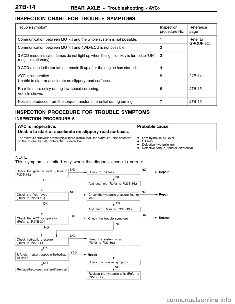
INSPECTION CHART FOR TROUBLE SYMPTOMS
Trouble symptomInspection
procedure No.Reference
page
Communication between MUT-IIand the whole system is not possible.1Refer to
GROUP22
Communication between MUT-IIand 4WD-ECU is not possible.2
GROUP22.
3 ACD mode indicator lamps do not light up when the ignition key is turned to “ON”
(engine stationary).3
3 ACD mode indicator lamps remain lit up after the engine has started.4
AYC is inoperative.
Unable to start or accelerate on slippery road surfaces.527B-14
Rear tires are noisy during low-speed cornering.
Vehicle skews.627B-15
Noise is produced from the torque transfer differential during turning.727B-15
INSPECTION PROCEDURE FOR TROUBLE SYMPTOMS
INSPECTION PROCEDURE 5
AYC is inoperative.
Unable to start or accelerate on slippery road surfaces.
Probable cause
The hydraulic oil level is probably low, there is an oil leak, the hydraulic unit is defective,
or the torque transfer differential is defective.DLow hydraulic oil level
DOil leak
DDefective hydraulic unit
DDefective torque transfer differential
NOTE
This symptom is limited only when the diagnosis code is correct.
NG
Replace the hydraulic unit. (Refer to
P.27B-61.)
NG
Add fluid. (Refer to P.27B-19.)
OKRepair
Check the trouble symptom.NO
Replace the torque transfer differential.
OK
Is foreign matter trapped in the hydrau-
lic line?YES
Repair
OK
Check the fluid level.
(Refer to P.27B-19.)Check the hydraulic pressure line for
leak.
OK
Add gear oil. (Refer to P.27B-16.)
OK
Check hydraulic pressure.
(Refer to P.27-21.)NGBleed the system of air.
(Refer to P.27-19.)
Check the gear oil level. (Refer to
P.27B-16.)NGCheck for oil leak.NG
Repair
Check the AYC for operation.
(Refer to P.27B-20.)Check the trouble symptom. OKOK
NGNormal
NGNG
Page 961 of 1449

REAR AXLE -Troubleshooting
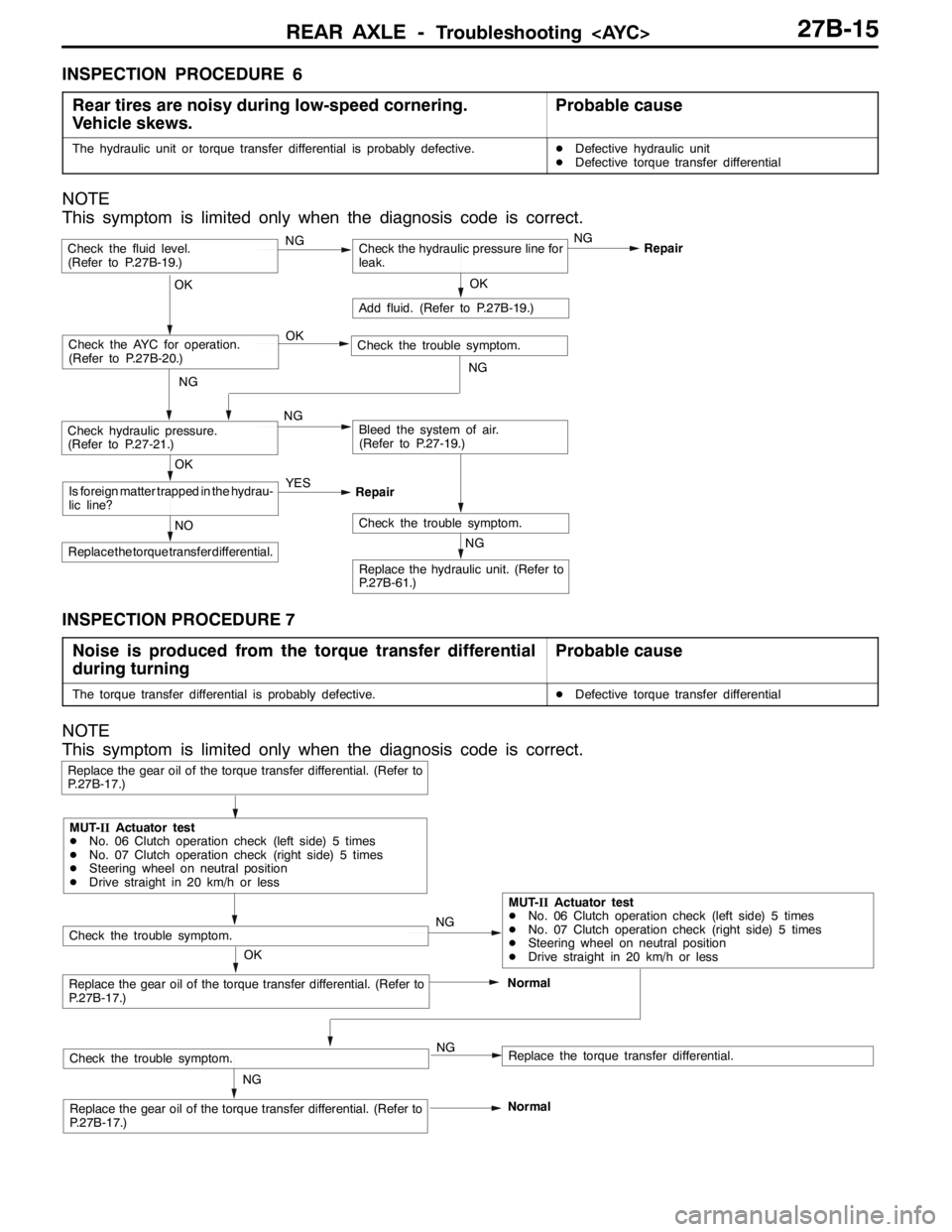
INSPECTION PROCEDURE 6
Rear tires are noisy during low-speed cornering.
Vehicle skews.
Probable cause
The hydraulic unit or torque transfer differential is probably defective.DDefective hydraulic unit
DDefective torque transfer differential
NOTE
This symptom is limited only when the diagnosis code is correct.
NG
Replace the hydraulic unit. (Refer to
P.27B-61.)
NG
Add fluid. (Refer to P.27B-19.)
OKRepair
Check the trouble symptom.NO
Replace the torque transfer differential.
OK
Is foreign matter trapped in the hydrau-
lic line?YES
Repair
Check the fluid level.
(Refer to P.27B-19.)Check the hydraulic pressure line for
leak.
OK
Check hydraulic pressure.
(Refer to P.27-21.)NGBleed the system of air.
(Refer to P.27-19.)
Check the AYC for operation.
(Refer to P.27B-20.)Check the trouble symptom. OK
NG
NGNG
INSPECTION PROCEDURE 7
Noise is produced from the torque transfer differential
during turning
Probable cause
The torque transfer differential is probably defective.DDefective torque transfer differential
NOTE
This symptom is limited only when the diagnosis code is correct.
NG
Replace the gear oil of the torque transfer differential. (Refer to
P.27B-17.)
Replace the gear oil of the torque transfer differential. (Refer to
P.27B-17.)Normal
Replace the gear oil of the torque transfer differential. (Refer to
P.27B-17.)
Replace the torque transfer differential.
Check the trouble symptom.
OKNG
NG
MUT-IIActuator test
DNo. 06 Clutch operation check (left side) 5 times
DNo. 07 Clutch operation check (right side) 5 times
DSteering wheel on neutral position
DDrive straight in 20 km/h or less
MUT-IIActuator test
DNo. 06 Clutch operation check (left side) 5 times
DNo. 07 Clutch operation check (right side) 5 times
DSteering wheel on neutral position
DDrive straight in 20 km/h or less
Check the trouble symptom.
Normal