2007 MITSUBISHI LANCER EVOLUTION battery replacement
[x] Cancel search: battery replacementPage 947 of 1449

27B-1
REAR AXLE
CONTENTS
GENERAL INFORMATION 2...................
SERVICE SPECIFICATIONS 3.................
LUBRICANTS 3..............................
SEALANTS 4................................
SPECIAL TOOLS 4...........................
TROUBLESHOOTING (AYC) 8.................
ON-VEHICLE SERVICE 16....................
Rear Axle Total Backlash Check 16...............
Gear Oil Level Check 16........................
Gear Oil Change 17............................
Fluid Level Check 19............................
Bleeding 19....................................
AYC Operation Check 20........................
Oil Pressure Check 21..........................Wheel Bearing Axial Play Check 22...............
Wheel Bearing Rotary-sliding Resistance Check 22.
Hub Bolt Replacement 23.......................
Differential Carrier Oil Seal Replacement 23........
Action When Battery Runs Out 24................
REAR HUB ASSEMBLY 25....................
KNUCKLE 28................................
DRIVE SHAFT 29.............................
DIFFERENTIAL CARRIER
DIFFERENTIAL CARRIER
HYDRAULIC UNIT
Page 1071 of 1449

35B-1
ANTI-SKID
BRAKING SYSTEM
(ABS) <4WD>
CONTENTS
GENERAL INFORMATION 2..................
SERVICE SPECIFICATIONS 3.................
LUBRICANTS Refer to GROUP 35A..........
SEALANT Refer to GROUP 35A..............
SPECIAL TOOLS 4...........................
TROUBLESHOOTING 4.......................
ON-VEHICLE SERVICE 26....................
Brake Pedal Check and Adjustment
Refer to GROUP 35A ..........................
Brake Booster Operating Test
Refer to GROUP 35A ..........................
Check Valve Operation Check
Refer to GROUP 35A ..........................
Bleeding Refer to GROUP 35A..................
Brake Fluid Level Sensor Check
Refer to GROUP 35A ..........................
Disc Brake Pad Check and
Replacement Refer to GROUP 35A..............Disc Brake Rotor Check Refer to GROUP 35A...
Brake Disc Thickness Check
Refer to GROUP 35A ..........................
Brake Disc Run-out Check and Correction
Refer to GROUP 35A ..........................
Wheel Speed Sensor Output Voltage Check
26 ............................................
Hydraulic Unit Check 28........................
Remedy for a Flat Battery 29...................
BRAKE PEDAL Refer to GROUP 35A........
MASTER CYLINDER AND BRAKE
BOOSTER Refer to GROUP 35A............
DISC BRAKE Refer to GROUP 35A..........
HYDRAULIC UNIT AND ABS-ECU 30.........
WHEEL SPEED SENSOR 33..................
G SENSORS AND STEERING WHEEL
SENSOR 35..................................
Page 1322 of 1449

54A-2
CHASSIS
ELECTRICAL
CONTENTS
BATTERY 4..............................
SERVICE SPECIFICATION 4....................
ON-VEHICLE SERVICE 4......................
Fluid Level and Specific Gravity Check 4........
Charging 4.................................
Battery Testing Procedure 5...................
IGNITION SWITCH AND IMMOBILIZER
SYSTEM 6...............................
SPECIAL TOOLS 6............................
TROUBLESHOOTING 6........................
IMMOBILIZER-ECU CHECK 10.................
IGNITION SWITCH 11..........................
COMBINATION METER 14................
SERVICE SPECIFICATIONS 14.................
SEALANT 14..................................
SPECIAL TOOLS 15...........................
TROUBLESHOOTING 15.......................
ON-VEHICLE SERVICE 19.....................Speedometer Check 19......................
Tachometer Check 20........................
Fuel Gauge Unit Check 20....................
Engine Coolant Temperature Gauge
Unit Check 21...............................
COMBINATION METER 22.....................
HEADLAMP ASSEMBLY 24...............
SERVICE SPECIFICATIONS 24.................
TROUBLESHOOTING 24.......................
ON-VEHICLE SERVICE 24.....................
Headlamp Aiming 24.........................
Headlamp Intensity Measurement 28...........
Headlamp Bulb(low beam)Replacement28 ....
Headlamp Bulb(high beam)Replacement29 ...
Position Lamp Bulb Replacement29 ...........
Front Turn Signal Lamp Bulb Replacement29 ...
Headlamp Auto Cut Adjustment Procedure29 ...
HeadlampAuto Cut Function Check 29.........
HEADLAMP ASSEMBLY 30....................
CONTINUED ON NEXT PAGE
Page 1348 of 1449

CHASSIS ELECTRICAL -Headlamp Assembly54A-28
HEADLAMP INTENSITY MEASUREMENT
1. Using a photometer, and following its manufacture’s
instruction manual.
2. Maintain an engine speed of 2,000 r/min., with the battery
in the charging condition
3. Set the headlamps to high beam
4. Measure the headlamp centre intensity (a point of H line
and V line) and check to be sure that the limit value
is satisfied.
Limit:
High beam 30,000 cd or more per one headlamp
NOTE
1. There may be special local regulations pertaining to
headlamp intensity, be sure to make any adjustments
necessary to satisfy such regulations.
2. If an illuminometer is used to make the measurements,
convert its values to photometer values by using the
following formula.
I=Er
2Where:
I=intensity (cd)
E=illumination (lux)
r=distance (m) from headlamps to illuminometer
Caution
1. On the headlamp not yet adjusted, perform aiming
with connector removed and the lamps switched off,
if applicable. In addition, care should be taken to
prevent a change of optical axis when connector is
reconnected.
2. Plastic outer lens are equipped with headlamps. When
lens surface is covered with materials for not
penetrating light, headlamp operation time should be
within 3 minutes. In addition, masking such as taping
should not be performed.
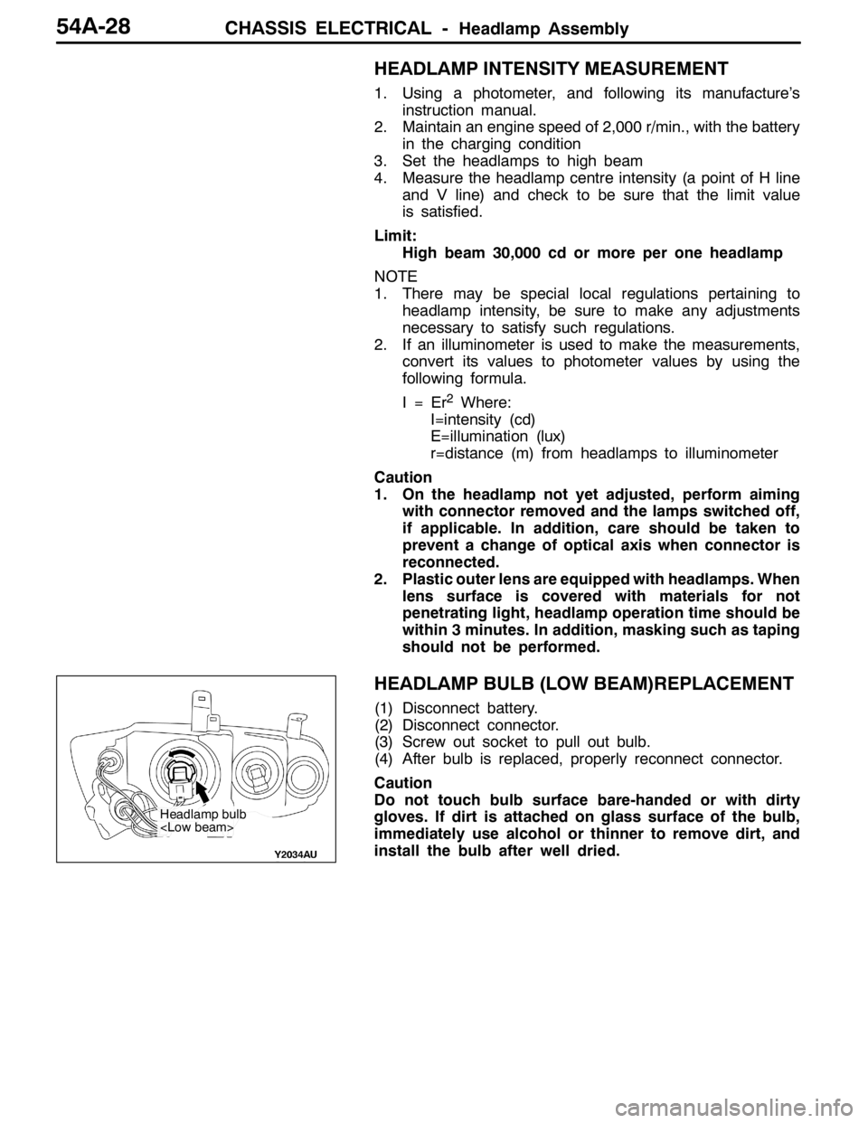
HEADLAMP BULB (LOW BEAM)REPLACEMENT
(1) Disconnect battery.
(2) Disconnect connector.
(3) Screw out socket to pull out bulb.
(4) After bulb is replaced, properly reconnect connector.
Caution
Do not touch bulb surface bare-handed or with dirty
gloves. If dirt is attached on glass surface of the bulb,
immediately use alcohol or thinner to remove dirt, and
install the bulb after well dried.
Headlamp bulb
Page 1349 of 1449

CHASSIS ELECTRICAL -Headlamp AssemblyCHASSIS ELECTRICAL -Headlamp AssemblyCHASSIS ELECTRICAL -Headlamp Assembly54A-29
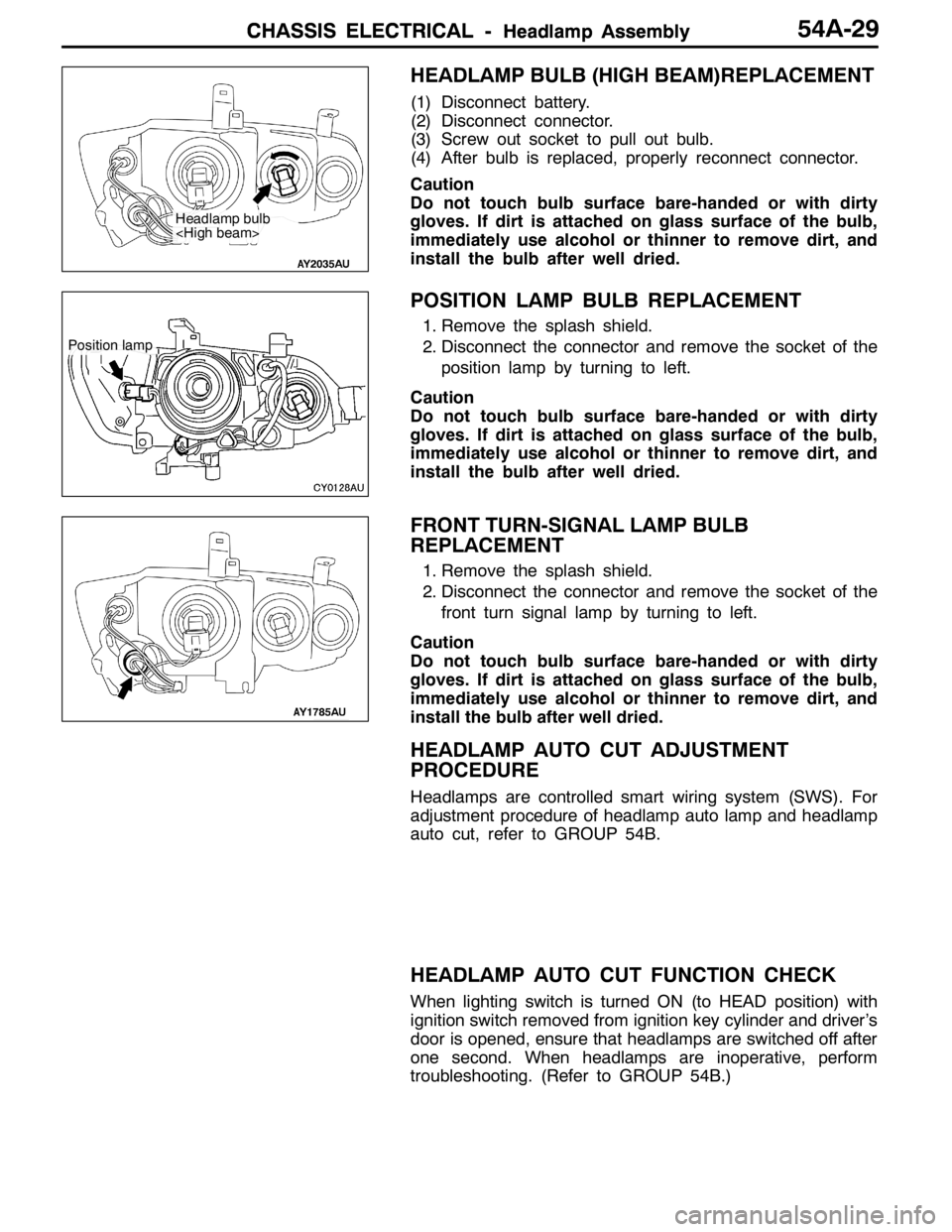
HEADLAMP BULB (HIGH BEAM)REPLACEMENT
(1) Disconnect battery.
(2) Disconnect connector.
(3) Screw out socket to pull out bulb.
(4) After bulb is replaced, properly reconnect connector.
Caution
Do not touch bulb surface bare-handed or with dirty
gloves. If dirt is attached on glass surface of the bulb,
immediately use alcohol or thinner to remove dirt, and
install the bulb after well dried.
POSITION LAMP BULB REPLACEMENT
1. Remove the splash shield.
2. Disconnect the connector and remove the socket of the
position lamp by turning to left.
Caution
Do not touch bulb surface bare-handed or with dirty
gloves. If dirt is attached on glass surface of the bulb,
immediately use alcohol or thinner to remove dirt, and
install the bulb after well dried.
FRONT TURN-SIGNAL LAMP BULB
REPLACEMENT
1. Remove the splash shield.
2. Disconnect the connector and remove the socket of the
front turn signal lamp by turning to left.
Caution
Do not touch bulb surface bare-handed or with dirty
gloves. If dirt is attached on glass surface of the bulb,
immediately use alcohol or thinner to remove dirt, and
install the bulb after well dried.
HEADLAMP AUTO CUT ADJUSTMENT
PROCEDURE
Headlamps are controlled smart wiring system (SWS). For
adjustment procedure of headlamp auto lamp and headlamp
auto cut, refer to GROUP 54B.
HEADLAMP AUTO CUT FUNCTION CHECK
When lighting switch is turned ON (to HEAD position) with
ignition switch removed from ignition key cylinder and driver’s
door is opened, ensure that headlamps are switched off after
one second. When headlamps are inoperative, perform
troubleshooting. (Refer to GROUP 54B.)
Headlamp bulb
Position lamp