2007 MITSUBISHI LANCER EVOLUTION key battery
[x] Cancel search: key batteryPage 368 of 1449

INDEX - In order of parts nameC-12
Wiring diagram
page Circuit diagram page Connector
No. Parts name
CColumn switchC-203B-104,107,112,116,125,128,137,141,
187,191B-22,28
Combination meterC-01B-84,87,95,103,106,118,122,126,129,
135,139,148,149,152,153,156,157,
198,206,214,222,230,240,248,250,
256, 258B-18,24
Combination meterC-02B-110,115,118,122,126,129,135,139,
148,149,152,153,156,157,198,206,
248, 250,256,258B-18,24
Condenser fan motorA-45B-177,183B-7,9
Condenser fan motorA-46B-177,183B-7,9
Condenser fan relay (HI)A-07XB-73,177,183B-6,8
Condenser fan relay (LO)A-06XB-73,177,183B-6,8
Control wiring harness and battery
wiring harness combinationB-14B-79,84,91,99,157B-10,14
Control wiring harness and floor wiring
harness (LH) combination
Crank angle sensorB-121B-88,96B-13,16
DDefogger (-)F-06B-185B-38,39
Defogger (+)F-19B-185B-38,39
Defogger relayC-214B-54,55,78,185B-23,29
Detonation sensorB-122B-89,97B-13,17
Diagnosis connectorC-22B-92,100,105,108,113,117,119,123,
125,128,137,141,150,154,158,164,
170,172,188,189,204,205,219,227,
237,247,248,250,252,254B-18,24
Diagnosis connectorC-23B-92,100B-18,24
Direction valve (LH)
Direction valve (RH)
Door lock actuator (Front:LH)E-08B-170,173B-34,36
Door lock actuator (Front:RH)E-18B-171,172B-35,37
Door lock actuator (Rear:LH)E-12B-171,173B-34,36
Door lock actuator (Rear:RH)E-23B-171,173B-35,37
Door lock key cylinder switch (LH)E-17B-172B-37
Door lock key cylinder switch (RH)E-16B-170B-35
Door switch (Front:LH)D-13B-105,112,120,121,158B-30,32
Door switch (Front:RH)D-01B-108,116,120,121,164B-30,32
Page 1286 of 1449

SRS - SRS Maintenance52B-42
SRS MAINTENANCE
The SRS must be inspected by an authorized dealer 10 years
after the date of vehicle registration.
SRS WARNING LAMP CHECK
Turn the ignition switch to the ON position. Does the SRS
warning lamp illuminate for about 7 seconds, and then go
out? If yes, SRS system is functioning properly. If no, refer
to page 52B-6.
SRS COMPONENT VISUAL CHECK
Turn the ignition key to LOCK (OFF) position, disconnect
the negative ( - ) battery cable and tape the terminal.
Caution
Wait at least 60 seconds after disconnecting the battery
cable before doing any further work. (Refer to P.52B-3.)
SRS CONTROL UNIT (SRS-ECU)
1. Check SRS-ECU case and brackets for dents, cracks,
deformation or rust.
Caution
The SRS may not activate if the SRS-ECU is not
installed properly, which could result in serious injury
or death to the vehicle’s driver or front passenger.
2. Check connector for damage, and terminals for
deformation or rust.
Replace SRS-ECU if it fails visual check.
(Refer to P.52B-50.)
SRS warning lamp
Insulating tape
Battery
Battery
( - ) cable
SRS-ECU
Page 1294 of 1449

SRS - SRS-ECU52B-50
SRS AIR BAG CONTROL UNIT (SRS-ECU)
Caution
1. Disconnect the negative ( - ) battery terminal
and wait for 60 seconds or more before
starting work. Also, the disconnected
battery terminal should be insulated with
tape. (Refer to P.52B-3.)
2. Never attempt to disassemble or repair the
SRS-ECU. If faulty, just replace with a new
one.3. Do not drop or subject the SRS-ECU to
impact or vibration.
If denting, cracking, deformation, or rust are
found in the SRS-ECU, replace it with a new
one. Discard the old one.
4. After deployment of the air bags, replace
the SRS-ECU with a new one.
5. Never use an ohmmeter on or near the
SRS-ECU, and use only the special test
equipment described on P.52B-6.
REMOVAL AND INSTALLATION
Pre-removal Operation
DTurn Ignition Key to LOCK (OFF) Position.
DDisconnect the Negative ( - ) Battery Terminal.
12
4.9±1.0 N·m
4.9±1.0 N·m
4.9±1.0 N·m
3
Removal steps
DFront floor console
(Refer to GROUP 52A - Front floor
console.)
DRear heater duct B
1. SRS-ECU and SRS-ECU bracket
assembly
2. SRS-ECU
3. SRS-ECU bracketInstallation steps
3. SRS-ECU bracket
"AA2. SRS-ECU
1. SRS-ECU and SRS-ECU bracket
assembly
DRear heater duct B
DFront floor console
(Refer to GROUP 52A - Front floor
console.)
DNegative ( - ) battery terminal
connection
"BADPost-installation inspection
Page 1305 of 1449

SRS -Seat Belt with Pre-tensioner52B-61
SEAT BELT WITH PRE-TENSIONER
Caution:
1. Wait for at least 60 seconds after
disconnecting the negative ( - ) terminal of
the battery before starting any operation.The
removed negative ( - ) terminal must be
protected by wrapping the tape. (Refer to
P.52B-3.)
2. Never disassemble or repair the seat belt
with pre-tensioner. Replace the part with a
new one when it malfunctions.
3. Take an extra care to deal with the seat belt
with pre-tensioner by avoiding dropping or
wetting it with water or oil. If any dent, crack,
or deformation is found, be sure to replace
the seat belt with pre-tensioner with a new
part.4. Do not place a heavy object on top of the
seat belt pre-tensioner.
5. Never keep the seat belt with pre-tensioner
in a place where the temperature can exceed
over 90_C.
6. Replace the seat belt with pre-tensioner with
a new one after operating the seat belt
pre-tensioner.
7. Wear gloves or protective glasses when
handling the seat belt with pre-tensioner
after operation.
8. If the seat belt with pre-tensioner before
operation needs to be discarded, be sure
to do so after operating the seat belt
pre-tensioner. (Refer to P.52B-64.)
REMOVAL AND INSTALLATION
Pre - removal operation
DTurn the ignition key to the LOCK(OFF) position.
DDisconnect the negative ( - ) terminal of the battery.
1 4
3
2
44±10 NSm
44±10 NSm
5
Removal steps
1. Sash cover guide
2. Seat belt lower anchor bolt
3. Bracket
4. Seat belt shoulder anchor bolt
DCenter pillar lower trim
(Refer to GROUP 52A - Trim.)
5. Seat belt pre-tensionerInstallation steps
"AA
DPre - installation inspection
5. Seat belt pre-tensioner
4. Seat belt shoulder anchor bolt
3. Bracket
2. Seat belt lower anchor bolt
DCenter pillar lower trim
(Refer to GROUP 52A - Trim.)
1. Sash cover guide
DNegative ( - ) terminal of the battery
connection
"BADPost - installation inspection
Page 1306 of 1449

SRS -Seat Belt with Pre-tensioner52B-62
INSTALLATION SERVICE POINTS
"AAPRE-INSTALLATION INSPECTION
1. Pre-installation inspection must be carried out even when
installing a new seat belt with pre-tensioner. (Refer to
Inspections.)
Caution
If the seat belt with pre-tensioner is discarded, discard
it after operating the seat belt pre-tensioner according
to the specified procedure. (Refer to P.52B-64.)
2. Connect the negative ( - ) terminal of the battery.
3. Connect the MUT-II to the diagnosis connector (16 pin).
Caution
Connection and disconnection of the MUT-II must be
carried out after turning the ignition switch to the
LOCK (OFF) position.
4. Turn the ignition switch to ON position.
5. Check that there is no abnormality except for open circuit
in the seat belt pre-tensioner after reading diagnostic
codes.
6. Turn the ignition key to LOCK (OFF) position.
7. Release the negative ( - ) terminal cable of the battery
and wrap a tape around it for insulation.
Caution
Wait for at least 60 seconds after disconnecting the
negative ( - ) battery cable before starting any
operation. (Refer to P.52B-3.)
"BAPOST-INSTALLATION INSPECTION
1. Turn the ignition switch to the ON position.
2. Check that the SRS warning lamp illuminates for 6 to
8 seconds and goes out.
3. Carry out troubleshooting if the lamp does not go out.
(Refer to P.52B-6.)
SRS warning lamp
Page 1329 of 1449

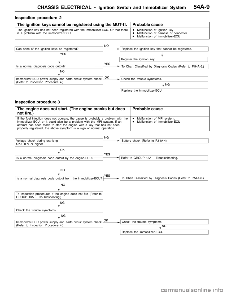
CHASSIS ELECTRICAL -Ignition Switch and Immobilizer System54A-9
Inspection procedure 2
The ignition keys cannot be registered using the MUT-II.
Probable cause
The ignition key has not been registered with the immobilizer-ECU. Or that there
is a problem with the immobilizer-ECU.DMalfunction of ignition key
DMalfunction of harness or connector
DMalfunction of immobilizer-ECU
Register the ignition key.
YES
NO YESIs a normal diagnosis code output?
NOCan none of the ignition keys be registered?Replace the ignition key that cannot be registered.
To Chart Classified by Diagnosis Codes (Refer to P.54A-6.)
OKImmobilizer-ECU power supply and earth circuit system check
(Refer to Inspection Procedure 4.)
NG
Replace the immobilizer-ECU.
Check the trouble symptoms.
Inspection procedure 3
The engine does not start. (The engine cranks but does
not fire.)
Probable cause
If the fuel injection does not operate, the cause is probably a problem with the
immobilizer-ECU, or it could also be a problem with the MPI system. If an
attempt has been made to start the engine with a key that has not been
properly registered, the above symptom is a sign of normal operation.DMalfunction of MPI system.
DMalfunction of immobilizer-ECU
NGBattery check (Refer to P.54A-4)
YES
NO
Refer to GROUP 13A - Troubleshooting.YES
NO
To Chart Classified by Diagnosis Codes (Refer to P.54A-6.)Is a normal diagnosis code output from the immobilizer-ECU?
OK
Voltage check during cranking
OK:8 V or higher
Is a normal diagnosis code output by the engine-ECU?
NG
OKImmobilizer-ECU power supply and earth circuit system check
(Refer to Inspection Procedure 4.)
NG
Replace the immobilizer-ECU.
Check the trouble symptoms.
Check the trouble symptoms.
NG
To inspection procedures if the engine does not fire (Refer to
GROUP 13A - Troubleshooting.)
Page 1349 of 1449

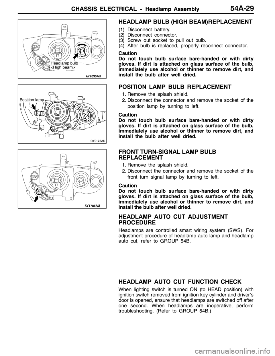
CHASSIS ELECTRICAL -Headlamp AssemblyCHASSIS ELECTRICAL -Headlamp AssemblyCHASSIS ELECTRICAL -Headlamp Assembly54A-29
HEADLAMP BULB (HIGH BEAM)REPLACEMENT
(1) Disconnect battery.
(2) Disconnect connector.
(3) Screw out socket to pull out bulb.
(4) After bulb is replaced, properly reconnect connector.
Caution
Do not touch bulb surface bare-handed or with dirty
gloves. If dirt is attached on glass surface of the bulb,
immediately use alcohol or thinner to remove dirt, and
install the bulb after well dried.
POSITION LAMP BULB REPLACEMENT
1. Remove the splash shield.
2. Disconnect the connector and remove the socket of the
position lamp by turning to left.
Caution
Do not touch bulb surface bare-handed or with dirty
gloves. If dirt is attached on glass surface of the bulb,
immediately use alcohol or thinner to remove dirt, and
install the bulb after well dried.
FRONT TURN-SIGNAL LAMP BULB
REPLACEMENT
1. Remove the splash shield.
2. Disconnect the connector and remove the socket of the
front turn signal lamp by turning to left.
Caution
Do not touch bulb surface bare-handed or with dirty
gloves. If dirt is attached on glass surface of the bulb,
immediately use alcohol or thinner to remove dirt, and
install the bulb after well dried.
HEADLAMP AUTO CUT ADJUSTMENT
PROCEDURE
Headlamps are controlled smart wiring system (SWS). For
adjustment procedure of headlamp auto lamp and headlamp
auto cut, refer to GROUP 54B.
HEADLAMP AUTO CUT FUNCTION CHECK
When lighting switch is turned ON (to HEAD position) with
ignition switch removed from ignition key cylinder and driver’s
door is opened, ensure that headlamps are switched off after
one second. When headlamps are inoperative, perform
troubleshooting. (Refer to GROUP 54B.)
Headlamp bulb
Position lamp
Page 1398 of 1449

SWS -Troubleshooting54B-34
CHECKS AT ECU TERMINALS
ETACS-ECU
*
Y0795AU
NOTE
*See the list below for data on the ETACS-ECU terminal 1 - 20 connectors. As the ETACS-ECU connects
directly onto the junction box, the voltages cannot be measured.
Terminal
No.Check itemsChecking requirementsNormal condition
1Power window relay outputWhen power windows operating
normallySystem voltage
2Battery power supply (for central
locking)Any timeSystem voltage
3Earth (for ECU)Any time0V
4Ignition switch (ACC)Ignition switch: ACCSystem voltage
5Room lamp outputWhen room lamps ON2 V or below
6---
7Door switch inputWhen any one door switch ON (door
open)0V
8Ignition switch (IG1) power supplyIgnition switch: ONSystem voltage
9Right-hand turn signal lamp outputWhen right-hand turn signal lamp ONSystem voltage
10Driver’s door switch inputWhen driver’s door switch ON (door
open)0V
11Battery power supply (for hazard
lamps)Any timeSystem voltage
12Central locking (lock) outputWhen door lock actuator operating
(locking operation)System voltage
13Central locking (unlock) output (NOT
driver’s door)When door lock actuator operating
(unlocking)System voltage
14Left-hand turn signal lamp outputWhen left-hand turn signal lamp ONSystem voltage
15 - 17---
18Ignition switch (ACC) power supplyIgnition switch: ACCSystem voltage
19Battery power supply for interior lampWhen interior lamp ONSystem voltage
20Battery power supply (for ECU)Any timeSystem voltage
21Rear fog lamp switch inputWhen the rear fog lamp switch ON0V
22Central locking (unlock) output (for
driver’s door)When door lock actuator operating
(unlocking)System voltage
23---
24 - 32---
33Door lock key cylinder switch input
(unlock switch)When driver’s door lock unlocked0V
34Door lock key cylinder switch input
(lock switch)When driver’s door lock locked0V