2007 MITSUBISHI LANCER EVOLUTION change wheel
[x] Cancel search: change wheelPage 1 of 1449

00
11
12
13
14
15
16
17
21
22
25
26
27
31
32
33
34
35
36
37
42
51
52
54
55
General........................
Engine .........................
Engine Lubrication .............
Fuel ...........................
Engine Cooling .................
Intake and Exhaust ............
Engine Electrical ...............
Engine and Emission Control ....
Clutch .........................
Manual Transmission ...........
Propeller Shaft .................
Front Axle ......................
Rear Axle ......................
Wheel and Tyre .................
Power Plant Mount ..............
Front Suspension ...............
Rear Suspension ...............
Service Brakes .................
Parking Brakes .................
Steering ........................
Body ...........................
Exterior ........................
Chassis Electrical ..............
Electrical Wiring ................
Body Repair ....................
WORKSHOP
MANUAL
FOREWORD
This Workshop Manual contains procedures for
service mechanics, including removal, disassembly,
inspection, adjustment, reassembly and
installation. Use the following manuals in
combination with this manual as required.
TECHNICAL INFORMATION MANUAL N0104CT9A
All information, illustrations and product
descriptions contained in this manual are current
as at the time of publication. We, however, reserve
the right to make changes at any time without prior
notice or obligation.
The EVOLUTION-VII is sold exclusively through
RALLIART Inc. Since the EVOLUTION-VII is a
rally-based model, it will not be warranted and will
not be homologated for general production.
Therefore, any service matters on the
EVOLUTION-VII should be inquired to RALLIART
Inc. as usual.
EMitsubishi Motors Corporation May 2001
Interior and Supplemental
Restraint System (SRS) ........
Heater, Air Conditioner and
Ventilation .....................
Page 169 of 1449

CIRCUIT DIAGRAMSB-71
MULTI-PURPOSE FUSE (In junction block)
Power supply
circuitNo.Rated
capacity (A)Identification
colourCircuit
Ignition
switch
IG1110RedIgnition coil
switch
27.5BrownColumn switch, combination meter, ETACS-ECU,
SRS-ECU, vehicle speed sensor and ACD mode
changeover switch
37.5BrownETACS-ECU and SRS-ECU
4---
IG257.5BrownA/C compressor relay, A/C-ECU, blower relay,
condenser fan relay, defogger relay, front-ECU,
4WD-ECU, steering wheel sensor and inter cooler
water splay relay
Multi-purpose fuse
No. 20 (Defogger
relay)6---
Ignition
switch
ACC720YellowFront-ECU and windshield wiper motor
switch
IG187.5BrownEngine-ECU and fuel pump relay (1) and fuel pump
relay (2)
ACC915BlueCigarette lighter
10---
117.5BrownA/C-ECU and remote controlled mirror switch
IG2127.5BrownABS-ECU, G-sensor (longitudinal) and G-sensor
(lateral)
ACC13---
14---
Fusible link No. 1
Battery/alternator
1515BlueDiagnosis connector
Battery/alternator
1610RedRear fog lamp relay
1710RedETACS-ECU
18---
1930GreenBlower motor and resistor
2030GreenDefogger
Page 585 of 1449

MPI -Troubleshooting
Fig. 1
Vehicle
speedInitial ac-
celerator
pedal de-
pressionNormalHesitation
Sag
TimeFig. 2
Normal
Initial ac-
celerator
pedal de-
pression
IdlingStumble
Time Vehicle
speed
13A-53
PROBLEM SYMPTOMS TABLE (FOR YOUR INFORMATION)
ItemsSymptom
StartingWon’t startThe starter is used to crank the engine, but there is no combustion within the
cylinders, and the engine won’t start.
Fires up and diesThere is combustion within the cylinders, but then the engine soon stalls.
Hard startingEngine starts after cranking a while.
Idling
stability
HuntingEngine speed doesn’t remain constant; changes at idle.
stability
Rough idleUsually, a judgement can be based upon the movement of the tachometer
pointer, and the vibration transmitted to the steering wheel, shift lever, body, etc.
This is called rough idle.
Incorrect idle speedThe engine doesn’t idle at the usual correct speed.
Engine stall
(Die out)The engine stalls when the foot is taken from the accelerator pedal, regardless
of whether the vehicles is moving or not.
Engine stall
(Pass out)The engine stalls when the accelerator pedal is depressed or while it is being
used.
DrivingHesitation Sag“Hesitation” is the delay in response of the vehicle speed (engine speed) that
occurs when the accelerator is depressed in order to accelerate from the speed
at which the vehicle is now traveling, or a temporary drop in vehicle speed
(engine speed) during such acceleration.
Serious hesitation is called “sag”. (Refer to Fig. 1)
Poor accelerationPoor acceleration is inability to obtain an acceleration corresponding to the
degree of throttle opening, even though acceleration is smooth, or the inability
to reach maximum speed.
StumbleEngine speed increase is delayed when the accelerator pedal is initially
depressed for acceleration. (Refer to Fig. 2)
ShockThe feeling of a comparatively large impact or vibration when the engine is
accelerated or decelerated.
SurgeThis is repeated surging ahead during constant speed travel or during variable
speed travel.
KnockingA sharp sound like a hammer striking the cylinder walls during driving and which
adversely affects driving.
StoppingRun on
(“Dieseling”)The condition in which the engine continues to run after the ignition switch is
turned to “LOCK” (OFF) position. Also called “Dieseling”.
Page 810 of 1449

22A-2
MANUAL
TRANSMISSION
CONTENTS
GENERAL 3.................................
Outline of Changes 3...........................
GENERAL INFORMATION 3..................
SERVICE SPECIFICATION 3..................
LUBRICANTS 3..............................
SPECIAL TOOLS 4...........................
TROUBLESHOOTING
ON-VEHICLE SERVICE 40....................
Transmission Oil Check 40......................
Transmission Oil Replacement 40................
Transfer Oil Check 40..........................
Transfer Oil Replacement 40....................
Fluid Check
Bleeding
Hydraulic Pressure Check
Wheel Speed Sensor Output Voltage
Measurement
TRANSMISSION CONTROL* 46...............
TRANSFER ASSEMBLY 49...................
TRANSMISSION ASSEMBLY 52...............
4WD-ECU
SENSOR, SWITCH AND RELAY
AYC> 56.....................................
HYDRAULIC UNIT Refer to GROUP27B.......
WARNING REGARDING SERVICING OF SUPPLEMENTAL RESTRAINT SYSTEM (SRS) EQUIPPED VEHICLES
WARNING!
(1) Improper service or maintenance of any component of the SRS, or any SRS-related component, can lead to personal
injury or death to service personnel (from inadvertent firing of the air bag) or to driver and passenger (from rendering
the SRS inoperative).
(2) Service or maintenance of any SRS component or SRS-related component must be performed only at an authorized
MITSUBISHI dealer.
(3) MITSUBISHI dealer personnel must thoroughly review this manual, and especially its GROUP 52B - Supplemental
Restraint System (SRS) before beginning any service or maintenance of any component of the SRS or any SRS-related
component.
NOTE
The SRS includes the following components: SRS-ECU, SRS warning lamp, air bag module, clock spring, and interconnecting
wiring. Other SRS-related components (that may have to be removed/installed in connection with SRS service or maintenance) are
indicated in the table of contents by an asterisk (*).
Page 817 of 1449

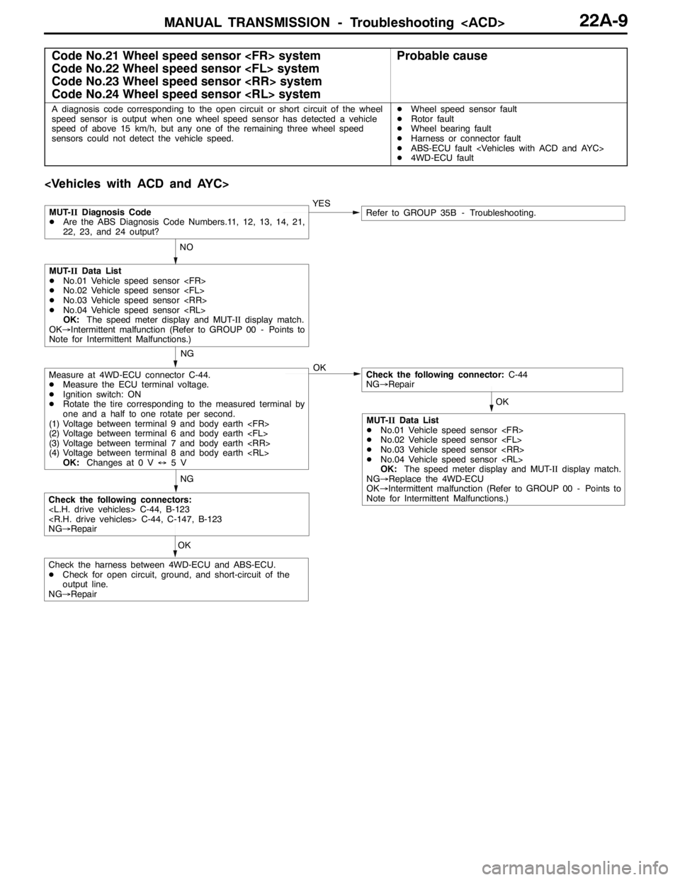
MANUAL TRANSMISSION - Troubleshooting
Code No.21 Wheel speed sensor
Code No.22 Wheel speed sensor
Code No.23 Wheel speed sensor
Code No.24 Wheel speed sensor
A diagnosis code corresponding to the open circuit or short circuit of the wheel
speed sensor is output when one wheel speed sensor has detected a vehicle
speed of above 15 km/h, but any one of the remaining three wheel speed
sensors could not detect the vehicle speed.DWheel speed sensor fault
DRotor fault
DWheel bearing fault
DHarness or connector fault
DABS-ECU fault
D4WD-ECU fault
OKNGYES
NO
OK
Measure at 4WD-ECU connector C-44.
DMeasure the ECU terminal voltage.
DIgnition switch: ON
DRotate the tire corresponding to the measured terminal by
one and a half to one rotate per second.
(1) Voltage between terminal 9 and body earth
(2) Voltage between terminal 6 and body earth
(3) Voltage between terminal 7 and body earth
(4) Voltage between terminal 8 and body earth
OK:Changes at 0 V↔5VCheck the following connector:C-44
NG→Repair
Check the following connectors:
NG→Repair
MUT-IIDiagnosis Code
DAre the ABS Diagnosis Code Numbers.11, 12, 13, 14, 21,
22, 23, and 24 output?Refer to GROUP 35B - Troubleshooting.
NG
MUT-IIData List
DNo.01 Vehicle speed sensor
DNo.02 Vehicle speed sensor
DNo.03 Vehicle speed sensor
DNo.04 Vehicle speed sensor
OK:The speed meter display and MUT-IIdisplay match.
OK→Intermittent malfunction (Refer to GROUP 00 - Points to
Note for Intermittent Malfunctions.)
OK
Check the harness between 4WD-ECU and ABS-ECU.
DCheck for open circuit, ground, and short-circuit of the
output line.
NG→Repair
MUT-IIData List
DNo.01 Vehicle speed sensor
DNo.02 Vehicle speed sensor
DNo.03 Vehicle speed sensor
DNo.04 Vehicle speed sensor
OK:The speed meter display and MUT-IIdisplay match.
NG→Replace the 4WD-ECU
OK→Intermittent malfunction (Refer to GROUP 00 - Points to
Note for Intermittent Malfunctions.)
Page 819 of 1449

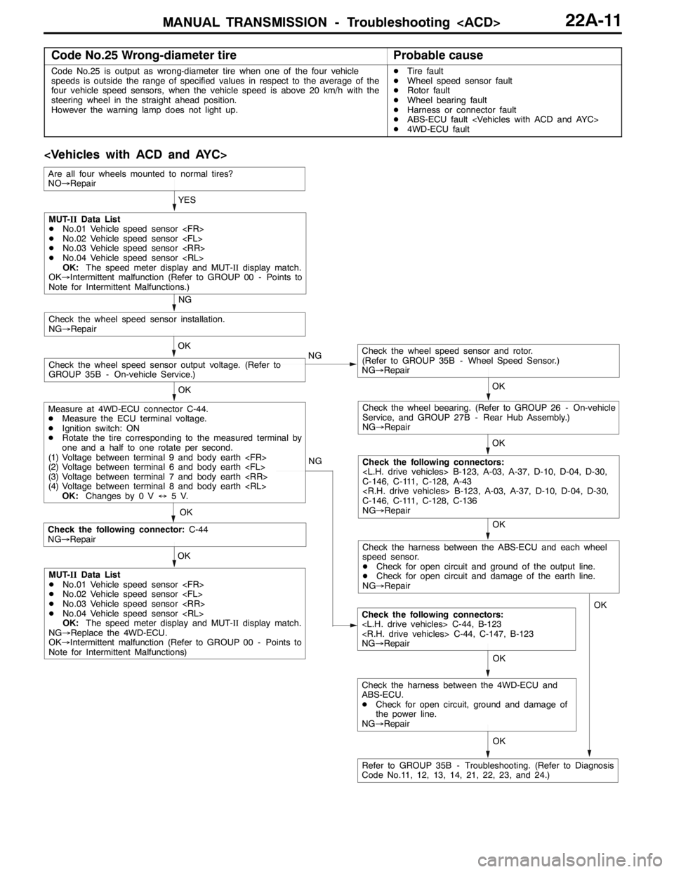
MANUAL TRANSMISSION - Troubleshooting
Code No.25 Wrong-diameter tireProbable cause
Code No.25 is output as wrong-diameter tire when one of the four vehicle
speeds is outside the range of specified values in respect to the average of the
four vehicle speed sensors, when the vehicle speed is above 20 km/h with the
steering wheel in the straight ahead position.
However the warning lamp does not light up.DTire fault
DWheel speed sensor fault
DRotor fault
DWheel bearing fault
DHarness or connector fault
DABS-ECU fault
D4WD-ECU fault
OK NG
OK
Check the following connector:C-44
NG→Repair
Check the following connectors:
NG→Repair OKYES
OK
OK
Check the wheel speed sensor and rotor.
(Refer to GROUP 35B - Wheel Speed Sensor.)
NG→Repair
Check the wheel speed sensor output voltage. (Refer to
GROUP 35B - On-vehicle Service.)OK
Check the wheel speed sensor installation.
NG→Repair
NG
OK
Check the wheel beearing. (Refer to GROUP 26 - On-vehicle
Service, and GROUP 27B - Rear Hub Assembly.)
NG→Repair
OK
Check the following connectors:
C-146, C-111, C-128, A-43
C-146, C-111, C-128, C-136
NG→Repair NG
MUT-IIData List
DNo.01 Vehicle speed sensor
DNo.02 Vehicle speed sensor
DNo.03 Vehicle speed sensor
DNo.04 Vehicle speed sensor
OK:The speed meter display and MUT-IIdisplay match.
OK→Intermittent malfunction (Refer to GROUP 00 - Points to
Note for Intermittent Malfunctions.)
Measure at 4WD-ECU connector C-44.
DMeasure the ECU terminal voltage.
DIgnition switch: ON
DRotate the tire corresponding to the measured terminal by
one and a half to one rotate per second.
(1) Voltage between terminal 9 and body earth
(2) Voltage between terminal 6 and body earth
(3) Voltage between terminal 7 and body earth
(4) Voltage between terminal 8 and body earth
OK:Changes by 0 V↔5V.
MUT-IIData List
DNo.01 Vehicle speed sensor
DNo.02 Vehicle speed sensor
DNo.03 Vehicle speed sensor
DNo.04 Vehicle speed sensor
OK:The speed meter display and MUT-IIdisplay match.
NG→Replace the 4WD-ECU.
OK→Intermittent malfunction (Refer to GROUP 00 - Points to
Note for Intermittent Malfunctions)
Refer to GROUP 35B - Troubleshooting. (Refer to Diagnosis
Code No.11, 12, 13, 14, 21, 22, 23, and 24.)
Are all four wheels mounted to normal tires?
NO→Repair
Check the harness between the ABS-ECU and each wheel
speed sensor.
DCheck for open circuit and ground of the output line.
DCheck for open circuit and damage of the earth line.
NG→Repair
OK
Check the harness between the 4WD-ECU and
ABS-ECU.
DCheck for open circuit, ground and damage of
the power line.
NG→RepairOK
Page 821 of 1449

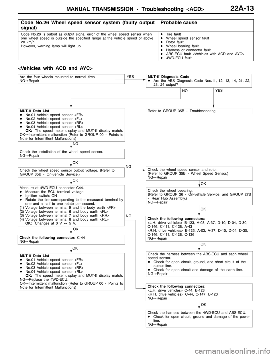
MANUAL TRANSMISSION - Troubleshooting
Code No.26 Wheel speed sensor system (faulty output
signal)Probable cause
Code No.26 is output as output signal error of the wheel speed sensor when
one wheel speed is outside the specified range at the vehicle speed of above
20 km/h.
However, warning lamp will light up.DTire fault
DWheel speed sensor fault
DRotor fault
DWheel bearing fault
DHarness or connector fault
DABS-ECU fault
D4WD-ECU fault
OK NG
OK
Check the following connector:C-44
NG→Repair
Check the following connectors:
NG→Repair OK
Check the harness between the 4WD-ECU and ABS-ECU.
DCheck for open circuit, ground and damage of the power
line.
NG→RepairYES
OK OK
Check the wheel speed sensor and rotor.
(Refer to GROUP 35B - Wheel Speed Sensor.)
NG→RepairCheck the wheel speed sensor output voltage. (Refer to
GROUP 35B - On-vehicle Service.)OK
Check the installation of the wheel speed sensor.
NG→Repair
NG
OK
Check the wheel beearing.
(Refer to GROUP 26 - On-vehicle Service, and GROUP 27B
- Rear Hub Assembly.)
NG→Repair
OK
Check the following connectors:
C-146, C-111, C-128, A-43
C-146, C-111, C-128, C-136
NG→Repair NG
MUT-IIData List
DNo.01 Vehicle speed sensor
DNo.02 Vehicle speed sensor
DNo.03 Vehicle speed sensor
DNo.04 Vehicle speed sensor
OK:The speed meter display and MUT-IIdisplay match.
OK→Intermittent malfunction (Refer to GROUP 00 - Points to
Note for Intermittent Malfunctions)
Measure at 4WD-ECU connector C44.
DMeasure the ECU terminal voltage.
DIgnition switch: ON
DRotate the tire corresponding to the measured terminal by
one and a half to one rotate per second.
(1) Voltage between terminal 9 and the body earth
(2) Voltage between terminal 6 and body earth
(3) Voltage between terminal 7 and body earth
(4) Voltage between terminal 8 and body earth
OK:Changes at 0 V↔5V.
MUT-IIData List
DNo.01 Vehicle speed sensor
DNo.02 Vehicle speed sensor
DNo.03 Vehicle speed sensor
DNo.04 Vehicle speed sensor
OK:The speed meter display and MUT-IIdisplay match.
NG→Replace the 4WD-ECU.
OK→Intermittent malfunction (Refer to GROUP 00 - Points to
Note for Intermittent Malfunctions)Check the harness between the ABS-ECU and each wheel
speed sensor.
DCheck for open circuit, ground, and short circuit of the
output line.
DCheck for open circuit and damage of the earth line.
NG→Repair YES
NO
Refer to GROUP 35B - Troubleshooting.
Are the four wheels mounted to normal tires.
NO→RepairMUT-IIDiagnosis Code
DAre the ABS Diagnosis Code Nos.11, 12, 13, 14, 21, 22,
23, 24 output?
Page 823 of 1449

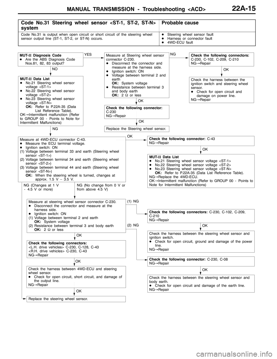
MANUAL TRANSMISSION - Troubleshooting
Code No.31 Steering wheel sensor
systemProbable cause
Code No.31 is output when open circuit or short circuit of the steering wheel
sensor output line (ST-1, ST-2, or ST-N) occurs.DSteering wheel sensor fault
DHarness or connector fault
D4WD-ECU fault
OK NG NO
OK
MUT-IIData List
DNo.21 Steering wheel sensor
voltage
DNo.22 Steering wheel sensor
voltage
DNo.23 Steering wheel sensor
voltage
OK:Refer to P.22A-35 (Data
List Reference Table).
OK→Intermittent malfunction (Refer
to GROUP 00 - Points to Note for
Intermittent Malfunctions)
Check the following connector:C-43
NG→Repair YES
MUT-IIDiagnosis Code
DAre the ABS Diagnosis Code
Nos.81, 82, 83 output?
MUT-IIData List
DNo.21 Steering wheel sensor voltage
DNo.22 Steering wheel sensor voltage
DNo.23 Steering wheel sensor voltage
OK:Refer to P.22A-35 (Data List Reference Table).
NG→Replace the 4WD-ECU.
OK→Intermittent malfunction (Refer to GROUP 00 - Points to
Note for Intermittent Malfunctions)
NG (No change from 0 V or
from above 4.5 V)
Measure at 4WD-ECU connector C-43.
DMeasure the ECU terminal voltage.
DIgnition switch: ON
(1) Voltage between terminal 33 and earth (Steering wheel
sensor
(2) Voltage between terminal34and earth (Steering wheel
sensor
(3) Voltage between terminal44 andearth (Steering wheel
sensor
OK:When the steering wheel is turned, changes at
approx. 1.5 V – 3.5 V.
(1) NG
NG (Changes at 1 V
- 4.5 V or more)
OK
Check the harness between the steering wheel sensor and
ignition switch.
DCheck for open circuit, ground and damage of the power
line.
NG→Repair
Check the following connectors:C-230, C-102, C-209,
C-210
NG→Repair
OKOK
Check the following connectors:
NG→Repair
OK
Check the harness between 4WD-ECU and steering
wheel sensor.
DCheck for open circuit, short circuit, and damage of
the output line.
NG→Repair
Replace the steering wheel sensor.
Replace the Steering wheel sensor.
OK
OK
Check the following connector:
C-230
NG→RepairNG
Measure at Steering wheel sensor
connector C-230.
DDisconnect the connector and
measure at the harness side.
DIgnition switch: ON
DVoltage between terminal 2 and
earth
OK:System voltage
DResistance between terminal 3
and body earth
OK:2Ωor less
OK
Check the following connectors:
C-230, C-102, C-209, C-210
NG→Repair
Check the harness between the
ignition switch and steering wheel
sensor.
DCheck for open circuit and
damage on power line.
NG→Repair
(2) NG
OK
Check the harness between the steering wheel sensor and
body earth.
DCheck for open circuit and damage of the earth line.
NG→Repair
Check the following connector:C-230, C-08
NG→Repair
Measure at steering wheel sensor connector C-230.
DDisconnect the connector and measure at the
harness side.
DIgnition switch: ON
(1) Voltage between terminal 2 and earth
OK:System voltage
(2) Resistance between terminal 3 and body earth
OK:2Ωor less