2007 MITSUBISHI LANCER EVOLUTION wheel torque
[x] Cancel search: wheel torquePage 433 of 1449

ENGINE -Crankshaft Oil Seal11A-27
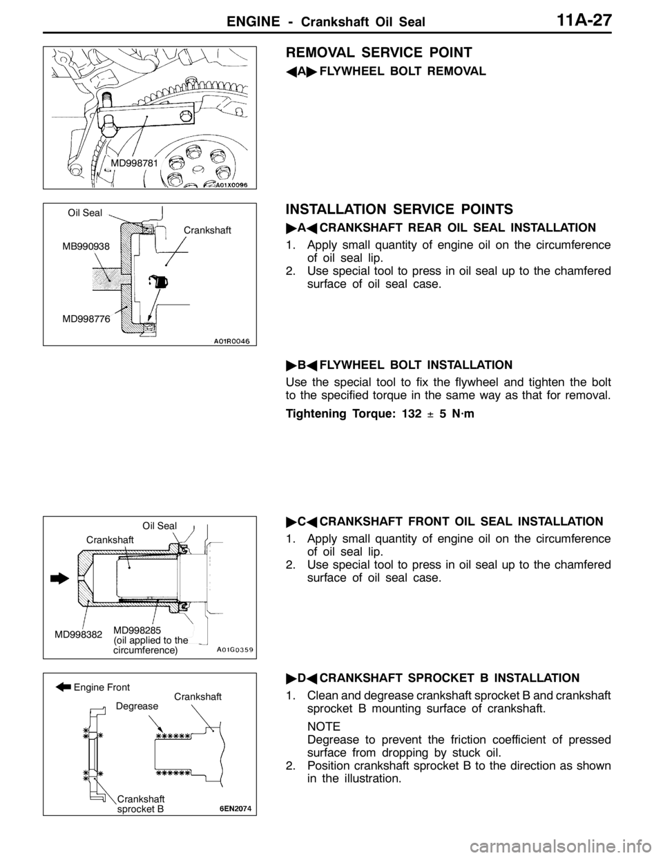
REMOVAL SERVICE POINT
AA"FLYWHEEL BOLT REMOVAL
INSTALLATION SERVICE POINTS
"AACRANKSHAFT REAR OIL SEAL INSTALLATION
1. Apply small quantity of engine oil on the circumference
of oil seal lip.
2. Use special tool to press in oil seal up to the chamfered
surface of oil seal case.
"BAFLYWHEEL BOLT INSTALLATION
Use the special tool to fix the flywheel and tighten the bolt
to the specified torque in the same way as that for removal.
Tightening Torque: 132±5 N·m
"CACRANKSHAFT FRONT OIL SEAL INSTALLATION
1. Apply small quantity of engine oil on the circumference
of oil seal lip.
2. Use special tool to press in oil seal up to the chamfered
surface of oil seal case.
"DACRANKSHAFT SPROCKET B INSTALLATION
1. Clean and degrease crankshaft sprocket B and crankshaft
sprocket B mounting surface of crankshaft.
NOTE
Degrease to prevent the friction coefficient of pressed
surface from dropping by stuck oil.
2. Position crankshaft sprocket B to the direction as shown
in the illustration.
MD998781
Crankshaft
Oil Seal
MB990938
MD998776
MD998382
Oil Seal
Crankshaft
MD998285
(oil applied to the
circumference)
Crankshaft
sprocket B
Degrease
Engine FrontCrankshaft
Page 461 of 1449

ENGINE OVERHAUL -Specifications11B-7
Items Tightening torque N·m
Water outlet fitting bolt10±1
Thermostat housing bolt23±4
Water inlet pipe bolt (M6)10±1
Water inlet pipe bolt (M8)13±2
Water pump bolt14±1
Knock sensor23±2
Rocker arm, camshaft
Cam position sensor bolt8.8±1.0
Cover bolt10±2
Cam position sensing cylinder bolt22±4
Cam position sensor support bolt14±1
Bearing cap bolt20±1
Oil delivery body bolt11±1
Cylinder head, valve
Cylinder head bolt78±2→Completely loosen→20±2→90_+90_
Oil pump, oil pan
Drain plug39±5
Oil pan bolt9±3
Oil screen bolt19±3
Baffle plate bolt22±4
Oil pressure switch19±3
Oil cooler bypass valve54±5
Relief plug44±5
Oil filter bracket bolt19±3
Plug cap23±3
Flange bolt36±3
Oil pump case bolt23±3
Oil pump cover bolt17±1
Oil pump cover screw10±2
Piston, connecting rod
Connecting rod cap nut20±2+90_-94_
Crankshaft, cylinder block
Flywheel bolt132±5
Rear plate bolt11±1
Bell housing cover bolt9±1
Rear oil seal case bolt11±1
Beam bearing cap bolt25±2+90_- 100_
Check valve32±2
Throttle body
Throttle position sensor bolt2.0±0.5
Turbocharger
Waste gate actuator bolt11.3±1.5
Page 473 of 1449

ENGINE OVERHAUL -Timing Belt11B-19
Caution
(1) Measure when the belt’s surface temperature is
close to room temperature.
(2) Make sure that water or oil, etc., do not get on
the mike.
(3) If strong winds contact the mike or if noise is
generated in the area while measuring, a value
that differs from the actual value may be indicated.
(4) If the measurement is carried out with the mike
contacted against the belt, a value that differs
from the actual value may be indicated.
(5) Do not measure while the engine is running.
11. Disconnect MUT-II.
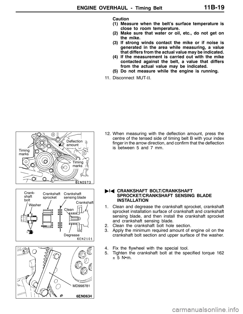
12. When measuring with the deflection amount, press the
centre of the tensed side of timing belt B with your index
finger in the arrow direction, and confirm that the deflection
is between 5 and 7 mm.
"IACRANKSHAFT BOLT/CRANKSHAFT
SPROCKET/CRANKSHAFT SENSING BLADE
INSTALLATION
1. Clean and degrease the crankshaft sprocket, crankshaft
sprocket installation surface of crankshaft and crankshaft
sensing blade, and then install the crankshaft sprocket
and crankshaft sensing blade.
2. Clean the crankshaft bolt hole section.
3. Apply the minimum required amount of engine oil on the
crankshaft bolt section and upper surface of the washer.
4. Fix the flywheel with the special tool.
5. Tighten the crankshaft bolt at the specified torque 162
±5N•m.
Timing
marks
Timing
marks
Deflection
amount
Crank-
shaft
bolt
WasherCrankshaft
sprocketCrankshaft
sensing blade
Crankshaft
Clean
Degrease
MD998781
Page 730 of 1449

INTAKE AND EXHAUST -Turbocharger15-24
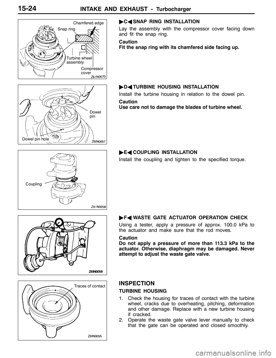
"CASNAP RING INSTALLATION
Lay the assembly with the compressor cover facing down
and fit the snap ring.
Caution
Fit the snap ring with its chamfered side facing up.
"DATURBINE HOUSING INSTALLATION
Install the turbine housing in relation to the dowel pin.
Caution
Use care not to damage the blades of turbine wheel.
"EACOUPLING INSTALLATION
Install the coupling and tighten to the specified torque.
"FAWASTE GATE ACTUATOR OPERATION CHECK
Using a tester, apply a pressure of approx. 100.0 kPa to
the actuator and make sure that the rod moves.
Caution
Do not apply a pressure of more than 113.3 kPa to the
actuator. Otherwise, diaphragm may be damaged. Never
attempt to adjust the waste gate valve.
INSPECTION
TURBINE HOUSING
1. Check the housing for traces of contact with the turbine
wheel, cracks due to overheating, pitching, deformation
and other damage. Replace with a new turbine housing
if cracked.
2. Operate the waste gate valve lever manually to check
that the gate can be operated and closed smoothly.
Snap ring
Turbine wheel
assembly
Compressor
cover Chamfered edge
Dowel
pin
Dowel pin hole
Coupling
Traces of contact
Page 845 of 1449

MANUAL TRANSMISSION - Troubleshooting
ACTUATOR TEST JUDGEMENT VALUE
Item
no.Check itemTest descriptionNormal state
01Bleeding
according to the steering angle, and operate
the Proportional valve for five minutes.Make sure no air leaks from the bleeder
screw on the transfer.
02Bleeding
according to the steering angle, and operate
the directional valve for five minutes.Make sure no air leaks from the bleeder
screw on the torque transfer differential.
03Check the oil vol-
umeOperate the directional valve to the left and
right for 20 seconds.Check that the oil volume of the reservoir
tank is appropriate.
04Electric pump
driveOperate the electric pump for 5 seconds.Operation sounds of the electric pump
can be heard.
05Check the opera-
tions of the ACDOperate the Proportional valve
supply the maximum oil pressure to the multi
plate clutch.9Generate the tight corner braking
phenomenon.
06Check clutch op-
erations
maximum oil pressure to the left clutch.When the wheels are lifted, speed
difference will occur between the rear
left and right wheels.
07Check clutch op-
erations
maximum oil pressure to the right clutch.When the wheels are lifted, speed
difference will occur between the rear
left and right wheels.
08Control OFFTurn OFF the electric pump relay, and turn
OFF the control of the ACD and AYC.In actual driving, there is difference
between control ON and OFF.
(1) The actuator test can be executed only when all the following conditions are satisfied.
DAll wheel speed sensor inputs below 20 km/h
DNo system malfunction detected
DSteering angle is within±30 degrees from the neutral position
(2) When the actuator test corresponds to one of the following conditions, forced driving will be cleared.
DWhen any one of the wheel speed sensor input is detected to be above 20 km/h (excluding
Item No.08 “Control OFF”.)
DWhen system malfunction is detected (excluding diagnostic code No.82, 84, and 85)
DWhen the forced drive time is exceeded
DWhen the MUT-IIis removed
DWhen the Clear key of the MUT-IIis operated
Page 850 of 1449

MANUAL TRANSMISSION - On-vehicle Service22A-42
BLEEDING
1. Lift up the vehicle.
2. Set the MUT-IIto the 16-pin diagnosis connector.
Caution
Turn the ignition switch to the “LOCK”(OFF) position
before connecting or disconnecting the MUT-II.
3. Turn the ignition switch to the “ON” position.
4. Set the steering wheel in the straight-ahead position.
5. Perform the MUT-IIactuator test (Item No.02), and forcibly
drive the hydraulic unit.
NOTE
(1) The actuator test (Item No.01: Bleeding Mode) will
be performed for 5 minutes, after which it will be
cleared automatically. Drive can also be cleared during
forced driving using the clear key of the MUT-II.
(2) If the hydraulic unit function has been stopped by
fail-safe, the hydraulic unit cannot be forcibly driven.
6. Remove the cap of the bleeder screw on the transfer,
and connect the vinyl hose.
7
.Slowly turn the steering wheel to the left or right from
the neutral state. Loosen the bleeder screw, and check
that air is discharged together with the fluid.
8
.After the air is discharged, tighten the bleeder screw,
and return the steering wheel to the neutral state.
Caution
During bleeding, replenish the fluid so that some
always remains in the oil reservoir.
9. Repeat steps 6 and 7 several 2 to 3 times, and after
checking that no more air mixes in, tighten the bleeder
screw at the specified torque.
Tightening torque: 5±1 N·m
10. After bleeding, check the fluid level. (Refer to P. 22A-41.)
Caution
If bleeding is not performed completely, noise may
be produced from the hydraulic unit, or the durability
of the pump, etc. may drop.
11. On vehicles with AYC, perform bleeding when the
hydraulic unit is removed. (Refer to GROUP 27B -
On-vehicle Service.)
ACD OPERATION CHECK
1. Lift up the vehicle.
2
.Set the MUT-IIto the 16-pin diagnosis connector.
Caution
Turn the ignition switch to the “LOCK”(OFF) position
before connecting or disconnecting the MUT-II.
3. Start the engine.
Bleeder screw
Front exhaust pipe
Page 852 of 1449

MANUAL TRANSMISSION - On-vehicle Service22A-44
(2) If the hydraulic unit function has been stopped by
fail-safe, the hydraulic unit cannot be forcibly driven.
6. Check that the generated oil pressure of the hydraulic
unit satisfies the standard value.
Standard value: 1.0 – 1.6 MPa
Caution
While the oil pressure is checked, add fluid as
necessary to ensure that it is left in the oil reservoir
during the entire procedure.
7. If the measured value exceeds the standard value, replace
the hydraulic unit.
8. Connect the hydraulic unit and transfer connector
assembly, and tighten the flare nut at the specified torque.
Tightening torque: 34±5 N·m (when screw is dry)
26±4 N·m (when screw is applied with oil)
9. Supply the specified fluid up to the MAX level of the
oil reservoir, and bleed the oil pressure pipes.
Specified fluid: DIA QUEEN ATF SP III
Quantity:
0.9 dm
3
1.0 dm3
WHEEL SPEED SENSOR OUTPUT VOLTAGE
MEASUREMENT
1. Lift the vehicle, and release the parking brake.
2. Disconnect the 4WD-ECU connector, and measure at
the connector of the harness.
Caution
Insert the probe from the harness of the connector.
Inserting in the terminal side may cause contact fault.
3. Rotate the measured wheel by about 1/2 to 1
rotations/second, and check the output voltage between
the following terminals using a circuit tester (AC mV range)
or oscilloscope.
Terminal No.
Front leftFront rightRear leftRear right
6987
19222120
Page 931 of 1449

FRONT AXLE -Service Specifications/Lubricants/Special Tools26-3
SERVICE SPECIFICATIONS
ItemStandard valueLimit
Wheel bearing axial play mm-0.06
WheelbearingrotationstartingtorqueN·m-103orlessWheelbearing rotation startingtorqueN·m-1.03orless
Setting of T.J. boot length mm85±3-
Opening dimension of the
special tool (MB991561) mmWhen the B.J.boot band
(small) is crimped.2.9-
When the B.J.boot band
(big) is crimped.3.2-
Crimped width of the B.J.boot band mm2.4 - 2.8-
LUBRICANTS
ItemsSpecified lubricantsQuantity g
T.J. boot greaseRepair kit grease120±10
B.J.boot greaseRepair kit grease11 0±10
SPECIAL TOOLS
ToolNumberNameUse
MB990767End yoke holderFixing of the hub
MB991618Hub bolt removerRemoval of the hub bolt
MB991113 or
MB990635Steering linkage
pullerDisconnection of ball joint
A
B
MB990241
A: MB990242
B: MB990244Axle shaft puller
A: Puller shaft
B: Puller barDRemoval of the drive shaft
DRemoval of the hub
MB991354Puller bodyDRemoval of the drive shaft
DRemoval of the hub