2007 MITSUBISHI LANCER EVOLUTION wheel torque
[x] Cancel search: wheel torquePage 1031 of 1449
FRONT SUSPENSION -On-vehicle Service33A-5
Tightening torque: 52±2 N·m
3. Confirm that the toe-in is at the standard value.
4. Use a turning radius gauge to check that the steering
angle is at the standard value.
Standard value:
Inner wheels31_45’±1_30’
Outer wheels (for reference)27_15’
TOE-OUT ANGLE ON TURNS
To check the steering linkage, especially after the vehicle
has been involved in an accident or if an accident is presumed,
it is advisable to check the toe-out angle on turns in addition
to the wheel alignment.
Conduct this test on the left turn as well as on the right turn.
Standard value:
ItemsSpecifications
Toe-out angle on turns
(inner wheel when outer wheel at 20_)22_00’±1_30’
CAMBER, CASTER AND KINGPIN INCLINATION
Standard value:
ItemsSpecifications
Camber
(Selectable from 2 options)-1_00’±30’* or - 2_00’±30’*
Caster3_55’±30’*
Kingpin inclination13_45’±1_30’
NOTE
1. *: difference between right and left wheels must be less
than 30’
2. Caster and kingpin inclination are preset at the factory
and cannot be adjusted.
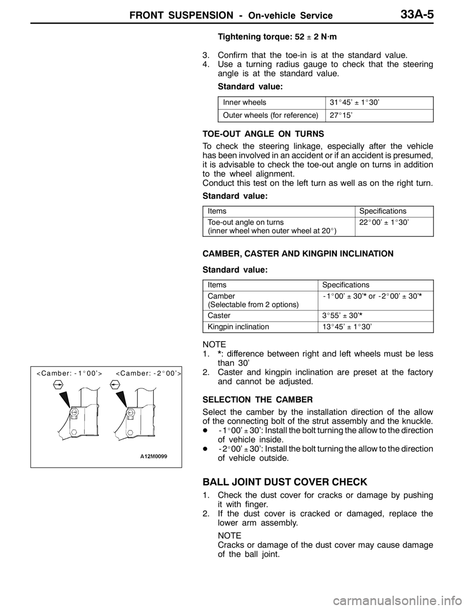
SELECTION THE CAMBER
Select the camber by the installation direction of the allow
of the connecting bolt of the strut assembly and the knuckle.
D-1
_00’±30’: Install the bolt turning the allow to the direction
of vehicle inside.
D-2
_00’±30’: Install the bolt turning the allow to the direction
of vehicle outside.
BALL JOINT DUST COVER CHECK
1. Check the dust cover for cracks or damage by pushing
it with finger.
2. If the dust cover is cracked or damaged, replace the
lower arm assembly.
NOTE
Cracks or damage of the dust cover may cause damage
of the ball joint.
Page 1056 of 1449
BASIC BRAKE SYSTEM -On-vehicle Service35A-14
BRAKE DISC THICKNESS CHECK
Caution: Brembo disc brake
Take care not to contact the parts or tools to the caliper
because the paint of caliper will be scratched. And if
there is brake fluid on the caliper, wipe out quickly.
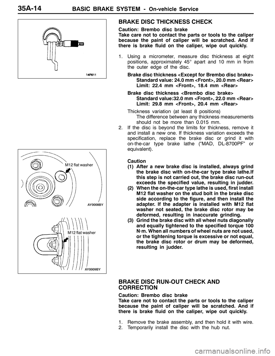
1. Using a micrometer, measure disc thickness at eight
positions, approximately 45°apart and 10 mm in from
the outer edge of the disc.
Brake disc thickness
Standard value: 24.0 mm
Limit: 22.4 mm
Brake disc thickness
Standard value:32.0 mm
Limit: 29.8 mm
Thickness variation (at least 8 positions)
The difference between any thickness measurements
should not be more than 0.015 mm.
2. If the disc is beyond the limits for thickness, remove it
and install a new one. If thickness variation exceeds the
specification, replace the brake disc or grind it with
on-the-car type brake lathe (“MAD, DL-8700PF” or
equivalent).
Caution
(1) After a new brake disc is installed, always grind
the brake disc with on-the-car type brake lathe.If
this step is not carried out, the brake disc run-out
exceeds the specified value, resulting in judder.
(2) When the on-the-car type lathe is used, first install
M12 flat washer on the stud bolt in the brake disc
side according to the figure, and then install the
adapter. If the adapter is installed with M12 flat
washer not seated, the brake disc rotor may be
deformed, resulting in inaccurate grinding.
(3) Grind the brake disc with all wheel nuts diagonally
and equally tightened to the specified torque 100
N·m. When all numbers of wheel nuts are not used,
or the tightening torque is excessive or not equal,
the brake disc rotor or drum may be deformed,
resulting in judder.
BRAKE DISC RUN-OUT CHECK AND
CORRECTION
Caution: Brembo disc brake
Take care not to contact the parts or tools to the caliper
because the paint of caliper will be scratched. And if
there is brake fluid on the caliper, wipe out quickly.
1. Remove the brake assembly, and then hold it with wire.
2. Temporarily install the disc with the hub nut.
M12 flat washer
M12 flat washer
Page 1057 of 1449
BASIC BRAKE SYSTEM -On-vehicle Service35A-15
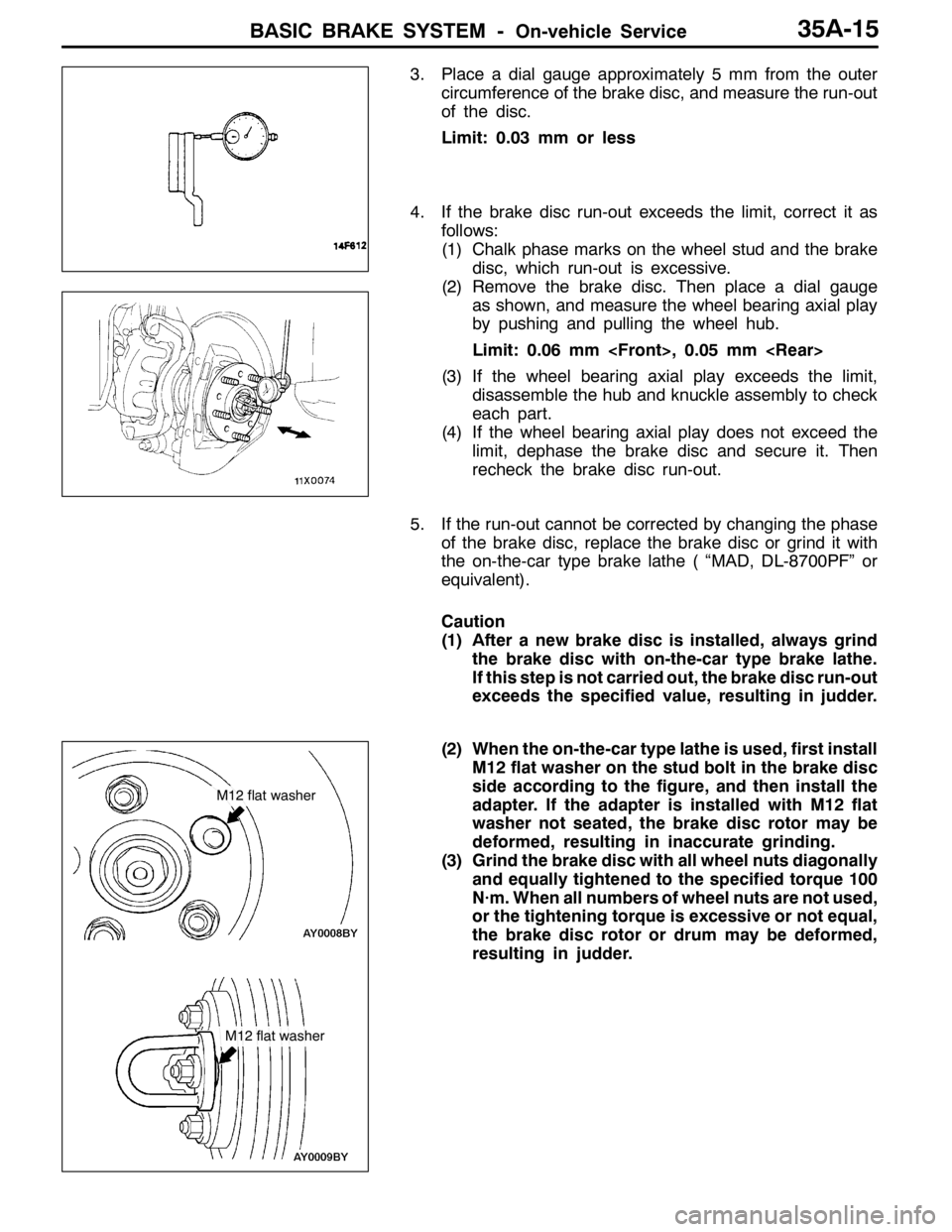
3. Place a dial gauge approximately 5 mm from the outer
circumference of the brake disc, and measure the run-out
of the disc.
Limit: 0.03 mm or less
4. If the brake disc run-out exceeds the limit, correct it as
follows:
(1) Chalk phase marks on the wheel stud and the brake
disc, which run-out is excessive.
(2) Remove the brake disc. Then place a dial gauge
as shown, and measure the wheel bearing axial play
by pushing and pulling the wheel hub.
Limit: 0.06 mm
(3) If the wheel bearing axial play exceeds the limit,
disassemble the hub and knuckle assembly to check
each part.
(4) If the wheel bearing axial play does not exceed the
limit, dephase the brake disc and secure it. Then
recheck the brake disc run-out.
5. If the run-out cannot be corrected by changing the phase
of the brake disc, replace the brake disc or grind it with
the on-the-car type brake lathe ( “MAD, DL-8700PF” or
equivalent).
Caution
(1) After a new brake disc is installed, always grind
the brake disc with on-the-car type brake lathe.
If this step is not carried out, the brake disc run-out
exceeds the specified value, resulting in judder.
(2) When the on-the-car type lathe is used, first install
M12 flat washer on the stud bolt in the brake disc
side according to the figure, and then install the
adapter. If the adapter is installed with M12 flat
washer not seated, the brake disc rotor may be
deformed, resulting in inaccurate grinding.
(3) Grind the brake disc with all wheel nuts diagonally
and equally tightened to the specified torque 100
N·m. When all numbers of wheel nuts are not used,
or the tightening torque is excessive or not equal,
the brake disc rotor or drum may be deformed,
resulting in judder.
M12 flat washer
M12 flat washer
Page 1115 of 1449

37A-1
STEERING
CONTENTS
GENERAL INFORMATION 2..................
SERVICE SPECIFICATIONS 4.................
LUBRICANTS 4..............................
SEALANT 4..................................
SPECIAL TOOLS 4...........................
ON-VEHICLE SERVICE 7.....................
Steering Wheel Free Play Check 7..............
Steering Angle Check 7........................
Tie Rod End Ball Joint Turning Torque Check 7..
Stationary Steering Effort Check 8...............
Checking Steering Wheel Return to Centre 8.....
Drive Belt Tension Check 8.....................Power Steering Fluid Level Check 9.............
Power Steering Fluid Replacement 9.............
Power Steering System Bleeding 9..............
Oil Pump Pressure Test 10.....................
Power Steering Oil Pressure Switch Check 11....
Ball Joint Dust Cover Check 11.................
STEERING WHEEL* 12.......................
STEERING SHAFT* 14.......................
POWER STEERING GEAR BOX AND
LINKAGE* 16................................
POWER STEERING OIL PUMP 29............
POWER STEERING OIL HOSES 30...........
WARNINGS REGARDING SERVICING OF SUPPLEMENTAL RESTRAINT SYSTEM (SRS) EQUIPPED VEHICLES
WARNING!
(1) Improper service or maintenance of any component of the SRS, or any SRS-related component, can lead to personal
injury or death to service personnel (from inadvertent firing of the air bag) or to the driver and passenger (from rendering
the SRS inoperative).
(2) Service or maintenance of any SRS component or SRS-related component must be performed only at an authorized
MITSUBISHI dealer.
(3) MITSUBISHI dealer personnel must thoroughly review this manual, and especially its GROUP 52B - Supplemental
Restraint System (SRS) before beginning any service or maintenance of any component of the SRS or any SRS-related
component.
NOTE
The SRS includes the following components: SRS-ECU, SRS warning lamp, air bag module, clock spring and interconnecting
wiring. Other SRS-related components (that may have to be removed/installed in connection with SRS service or maintenance) are
indicated in the table of contents by an asterisk (*).
Page 1118 of 1449

STEERING -Service Specifications/Lubricants/Sealant/Special Tools37A-4
SERVICE SPECIFICATIONS
ItemsStandard valueLimit
Steering wheel free play mmwhen engine running-30 or less
with engine stopped0-10-
Steering angleInner wheel31_45’±1_30’-
Outer wheel
Ball joint turning torque N·m1.0 - 3.0-
Stationary steering effort NSteering effort32 or less-
Fluctuation allowance6.0 or less-
Oil pump relief pressure MPa8.4 - 9.0-
Pressure under no-load conditions MPa0.2 - 0.8-
Steering gear retention hydraulic pressure MPa8.4 - 9.0-
Oil pressure switch operating
pressureMPa
OFF→ON1.8 - 2.4-
pressure MPaON→OFF1.0 - 2.4-
Total pinion torque N·mTotal rotation torque0.8 - 1.8-
Torque variation0.49 or less-
Tie rod joint swing resistance N (Tie rod joint swing torque N·m)8 - 27 (1.5 - 4.9)-
Opening dimension of special tool (MB991561) mm2.9-
Band crimped width mm2.4 - 2.8-
LUBRICANTS
ItemsSpecified lubricantQuantity
Power steering fluidAutomatic transmission fluid DEXRONIIApprox. 1.0 L
Tie rod bellowsSilicone greaseAs required
Pinion and valve assemblyRepair kit greaseAs required
Rack assembly
SEALANT
ItemsSpecified sealantRemarks
Toe boad (steering shaft cover
mounting bolt hole)3M ATD Part No. 8513 or equivalentDrying sealant
Rack support cover end plug3M ATD Part No. 8661, 8663 or equivalentSemi-drying sealant
SPECIAL TOOLS
ToolNumberNameUse
MB990635,
MB991113 or
MB991406Steering linkage
pullerDisconnection of tie rod end
Page 1119 of 1449

STEERING -Special Tools37A-5
Tool UseName Number
MB991006Preload socketMeasurement of the total pinion torque
MB990326Preload socketMeasurement of the ball joint turning torque
MB990993Power steering oil
pressure gauge
adapter (pump
side)Measurement of oil pressure
MB990994Power steering oil
pressure gauge
adapter (hose
side)
MB990662Oil pressure gauge
assemblyMeasurement of oil pressure
MB991204Torque wrench
socketDAdjustment of rack support
DRemoval of rack support cover
MB990784Ornament removerRemoval of steering wheel cover
MB990803Steering wheel
pullerDisconnection of the steering wheel
MB991199Oil seal and
bearing installerDPress fitting of rack housing bearing
DTo press in the oil seal for the rack
Page 1121 of 1449
STEERING -On-vehicle Service37A-7
ON-VEHICLE SERVICE
STEERING WHEEL FREE PLAY CHECK
1. With engine running (hydraulic operation), set front wheels
straight ahead.
2. Measure the play on steering wheel circumference before
wheels start to move when slightly moving steering wheel
in both directions.
Limit: 30 mm or less
3. When play exceeds the limit, check for play on steering
shaft connection and steering linkage. Correct or replace.
4. If the free play still exceeds the limit value, set steering
wheel straight ahead with engine stopped. Load 5 N
towards steering wheel circumference and check play.
Standard value: 0 - 10 mm
5. If the play exceeds the standard value, remove steering
gear box and check total pinion torque. (Refer to
P.37A-17.)
STEERING ANGLE CHECK
1. Locate front wheels on turning radius gauge and measure
steering angle.
Standard value:
Inner wheel31_45’±1_30’
Outer wheel
2. When the angle is not within the standard value, the
toe-in is probably incorrect. Adjust the toe-in.
Standard value: 0±2mm
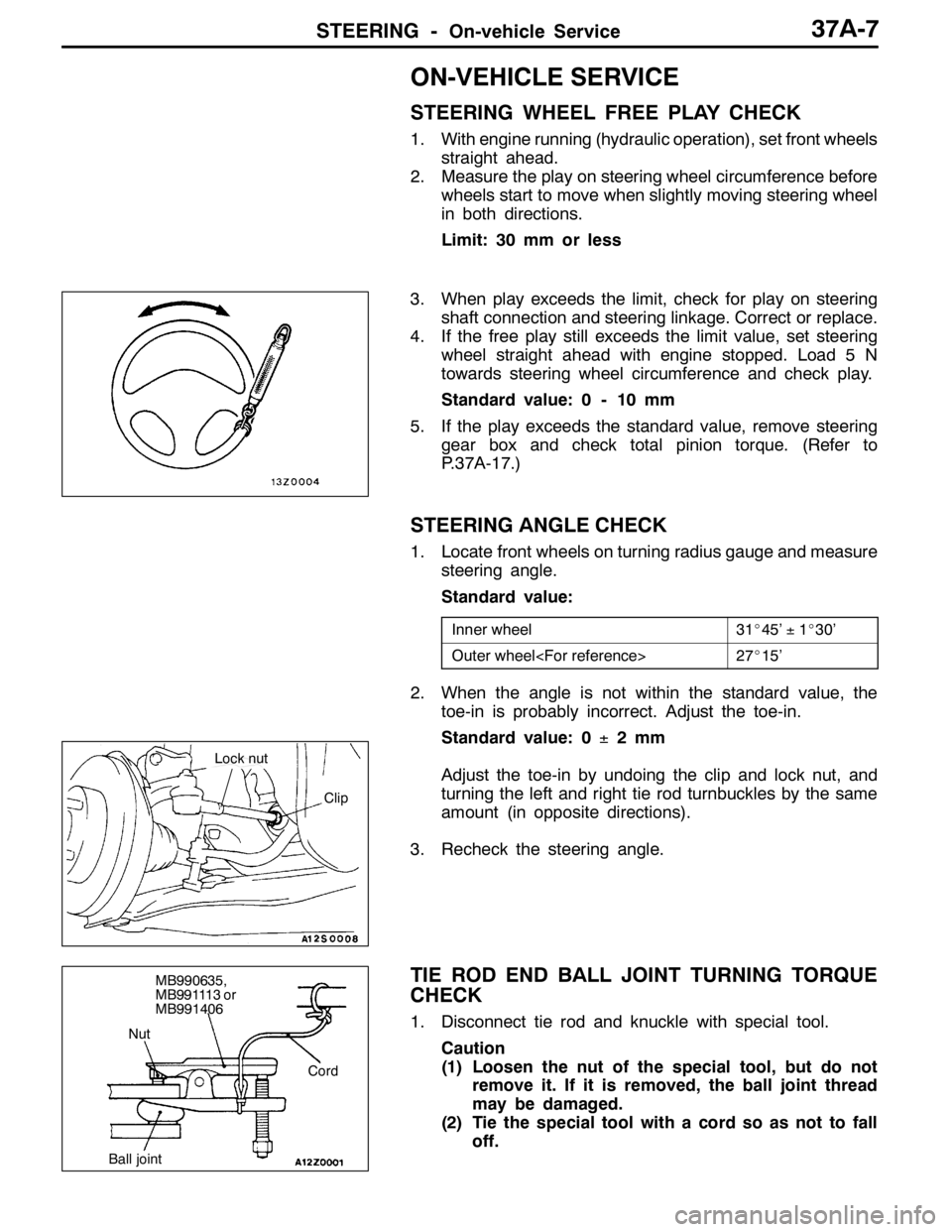
Adjust the toe-in by undoing the clip and lock nut, and
turning the left and right tie rod turnbuckles by the same
amount (in opposite directions).
3. Recheck the steering angle.
TIE ROD END BALL JOINT TURNING TORQUE
CHECK
1. Disconnect tie rod and knuckle with special tool.
Caution
(1) Loosen the nut of the special tool, but do not
remove it. If it is removed, the ball joint thread
may be damaged.
(2) Tie the special tool with a cord so as not to fall
off.
Clip
Lock nut
Cord
Ball jointNutMB990635,
MB991113 or
MB991406
Page 1122 of 1449
STEERING -On-vehicle Service37A-8
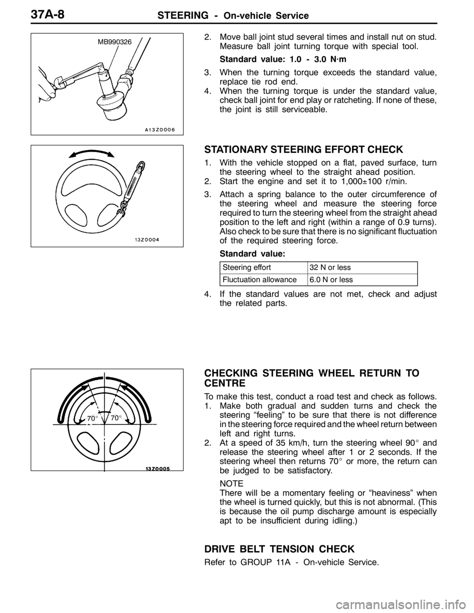
2. Move ball joint stud several times and install nut on stud.
Measure ball joint turning torque with special tool.
Standard value: 1.0 - 3.0 N·m
3. When the turning torque exceeds the standard value,
replace tie rod end.
4. When the turning torque is under the standard value,
check ball joint for end play or ratcheting. If none of these,
the joint is still serviceable.
STATIONARY STEERING EFFORT CHECK
1. With the vehicle stopped on a flat, paved surface, turn
the steering wheel to the straight ahead position.
2. Start the engine and set it to 1,000±100 r/min.
3. Attach a spring balance to the outer circumference of
the steering wheel and measure the steering force
required to turn the steering wheel from the straight ahead
position to the left and right (within a range of 0.9 turns).
Also check to be sure that there is no significant fluctuation
of the required steering force.
Standard value:
Steering effort32 N or less
Fluctuation allowance6.0 N or less
4. If the standard values are not met, check and adjust
the related parts.
CHECKING STEERING WHEEL RETURN TO
CENTRE
To make this test, conduct a road test and check as follows.
1. Make both gradual and sudden turns and check the
steering “feeling” to be sure that there is not difference
in the steering force required and the wheel return between
left and right turns.
2. At a speed of 35 km/h, turn the steering wheel 90_and
release the steering wheel after 1 or 2 seconds. If the
steering wheel then returns 70_or more, the return can
be judged to be satisfactory.
NOTE
There will be a momentary feeling or “heaviness” when
the wheel is turned quickly, but this is not abnormal. (This
is because the oil pump discharge amount is especially
apt to be insufficient during idling.)
DRIVE BELT TENSION CHECK
Refer to GROUP 11A - On-vehicle Service.
MB990326
70_70_