Page 968 of 1449

REAR AXLE -On-vehicle Service27B-22
8. If the measured value exceeds the standard value, replace
the hydraulic unit.
9. Connect the hydraulic unit and the hydraulic unit hose
assembly, and connect the torque transfer differential and
hydraulic unit hose assembly, tighten the flare nut in
specified torque.
Tightening torque: 34±5 N·m (Thread is not lubricated)
26±4 N·m (Thread is lubricated)
10. Supply the specified fluid up to the MAX level of the
oil reservoir, and bleed.
Specified fluid: ATF-SP III
Quantity: 1 L
WHEEL BEARING AXIAL PLAY CHECK
1. Remove the brake caliper and brake disc.
2. Check the bearing’s axial play.
Place a dial gauge against the hub surface; then move
the hub in the axial direction and check whether or not
there is axial play.
Limit: 0.05 mm
3. If the axial play exceeds the limit, the castle nut should
be tightened to the specified torque 225±25 N·m and
check the axial play again.
4. Replace the rear hub assembly if an adjustment cannot
be made to within the limit.
WHEEL BEARING ROTARY-SLIDING
RESISTANCE CHECK
1. Remove the brake caliper and brake disc.
2. After turning the hub a few times to seat the bearing,
wind a rope around the hub bolt and turn the hub by
pulling at a 90_angle with a spring balance. Measure
to determine whether or not the rotary-sliding resistance
of the rear hub is at the limit value.
Limit: 22 N or less
Page 1109 of 1449

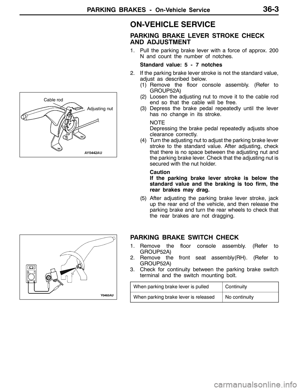
PARKING BRAKES -On-Vehicle Service36-3
ON-VEHICLE SERVICE
PARKING BRAKE LEVER STROKE CHECK
AND ADJUSTMENT
1. Pull the parking brake lever with a force of approx. 200
N and count the number of notches.
Standard value: 5 - 7 notches
2. If the parking brake lever stroke is not the standard value,
adjust as described below.
(1) Remove the floor console assembly. (Refer to
GROUP52A)
(2) Loosen the adjusting nut to move it to the cable rod
end so that the cable will be free.
(3) Depress the brake pedal repeatedly until the lever
has no change in its stroke.
NOTE
Depressing the brake pedal repeatedly adjusts shoe
clearance correctly.
(4) Turn the adjusting nut to adjust the parking brake lever
stroke to the standard value. After adjusting, check
that there is no space between the adjusting nut and
the parking brake lever. Check that the adjusting nut is
secured with the nut holder.
Caution
If the parking brake lever stroke is below the
standard value and the braking is too firm, the
rear brakes may drag.
(5) After adjusting the parking brake lever stroke, jack
up the rear end of the vehicle, and then release the
parking brake and turn the rear wheels to check that
the rear brakes are not dragging.
PARKING BRAKE SWITCH CHECK
1. Remove the floor console assembly. (Refer to
GROUP52A)
2. Remove the front seat assembly(RH). (Refer to
GROUP52A)
3. Check for continuity between the parking brake switch
terminal and the switch mounting bolt.
When parking brake lever is pulledContinuity
When parking brake lever is releasedNo continuity
Adjusting nut
Cable rod
Page 1112 of 1449
PARKING BRAKES -Parking Brake Cable36-6
PARKING BRAKE CABLE
REMOVAL AND INSTALLATION
CAUTION
If the vehicle is equipped with the Brembo disc brake, during maintenance, take care not to contact
the parts or tools to the caliper because the paint of caliper will be scratched. And if there is
brake fluid on the caliper, wipe out quickly.
Pre-removal Operation
DRear Floor Console Assembly and Rear Console
Bracket Removal (Refer to GROUP 52A-Floor
Console.)
DRear Seat Cushion Assembly Removal (Refer to
GROUP 52A-Seat.)Post-installation Operation
DParking Brake Lever Stroke Check and Adjustment
(Refer to P.36-3.)
DRear Seat Cushion Installation (Refer to GROUP
52A-Seat.)
DRear Floor Console Assembly and Rear Console
Bracket Installation (Refer to GROUP 52A-Floor
Console.)
1
Removal steps
DShoe and lining assembly
(Refer to P.36-7.)
DParking brake cable connection
(Refer to P.36-5.)
1. Parking brake cable
Page 1155 of 1449
BODY -Fuel Filler Door42-7
FUEL FILLER DOOR
REMOVAL AND INSTALLATION
Pre-removal and Post-installation Operations
DRear Seat Removal and Installation. (Refer to GROUP
52A.)
DFront Scuff Plate (Driver’s Side), Rear Scuff Plate(Driver’s Side), Center Pillar Lower Trim (Driver’s
Side), Quarter Trim (Driver’s Side) Removal and
Installation (Refer to GROUP 52A – Trim.)
5
1
3 4 3
2
5.0±1.0 N·m
Adjustment of clearance around
fuel filler door
Removal steps
1. Fuel filler door panel assembly
2. Clip
3. Fuel filler door hook assembly4. Fuel filler door lock release cable
5. Fuel filler door lock release handle