2007 MITSUBISHI LANCER EVOLUTION height
[x] Cancel search: heightPage 984 of 1449

REAR AXLE -Differential Carrier
DISASSEMBLY
19
2
6
8
20
22
26
5
113
4
9
12
15
16
1314
10
21
1
23
24
25
18
17
7
897
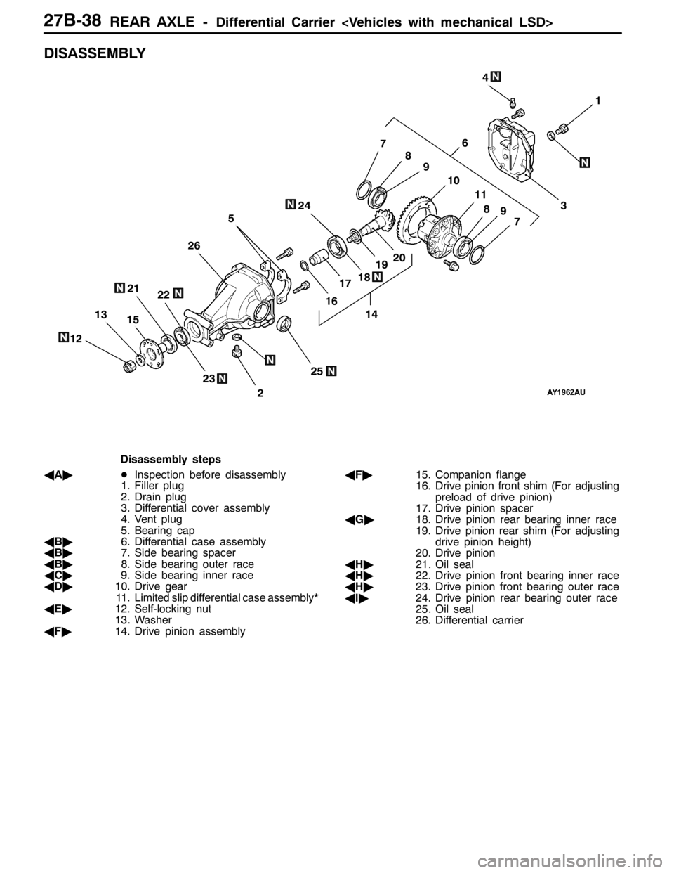
Disassembly steps
AA"DInspection before disassembly
1. Filler plug
2. Drain plug
3. Differential cover assembly
4. Vent plug
5. Bearing cap
AB"6. Differential case assembly
AB"7. Side bearing spacer
AB"8. Side bearing outer race
AC"9. Side bearing inner race
AD"10. Drive gear
11. Limited slip differential case assembly*
AE"12. Self-locking nut
13. Washer
AF"14. Drive pinion assemblyAF"15. Companion flange
16. Drive pinion front shim (For adjusting
preload of drive pinion)
17. Drive pinion spacer
AG"18. Drive pinion rear bearing inner race
19. Drive pinion rear shim (For adjusting
drive pinion height)
20. Drive pinion
AH"21. Oil seal
AH"22. Drive pinion front bearing inner race
AH"23. Drive pinion front bearing outer race
AI"24. Drive pinion rear bearing outer race
25. Oil seal
26. Differential carrier
Page 986 of 1449

REAR AXLE -Differential Carrier
2. Insert the brass between the differential carrier and the
differential case, and then rotate the companion flange
by hand (once in the normal direction, and then once
in the reverse direction) while applying a load to the drive
gear so that the revolution torque (approximate 2.5 -
3.0 N·m) is applied to the drive pinion.
Caution
If the drive gear is rotated too much, the tooth contact
pattern will become unclear and difficult to check.
3. Check the tooth contact condition of the drive gear and
drive pinion.
Standard tooth contact patternProblemSolution
1 Narrow tooth side
2 Drive-side tooth surface (the
side applying power during
forward movement)
3 Wide tooth side
4 Coast-side tooth surface (the
side applying power during
reverse movement)
1
2
34
Tooth contact pattern resulting from
excessive pinion height
The drive pinion is positioned too far
from the centre of the drive gear.
1 2
34
Increase the thickness of the drive
pinion rear shim, and position the
drive pinion closer to the centre of the
drive gear. Also, for backlash adjust-
ment, position the drive gear farther
from the drive pinion.
1 2
34
Tooth contact pattern resulting from
insufficient pinion height
The drive pinion is positioned too
close to the centre of the drive gear.
1 2
34
Decrease the thickness of the drive
pinion rear shim, and position the
drive pinion farther from the centre of
the drive gear. Also, for backlash
adjustment, position the drive gear
closer to the drive pinion.
1
2
34
NOTE
Checking the tooth contact pattern is the way to
confirm that the adjustments of the pinion height
and backlash have been done properly. Continue
to adjust the pinion height and backlash until the
tooth contact pattern resembles the standard
pattern.If, even after adjustments have been made, the
correct tooth contact pattern cannot be obtained,
it means that the drive gear and the drive pinion
have become worn beyond the allowable limit.
Replace the gear set.
MB990939
Page 989 of 1449

REAR AXLE -Differential Carrier
REASSEMBLY
11
14
26
25
1310
6
124
7
24
21
18
17
15
2019
9
3
8
5
2
1
22
23
16
191820
5
17
15
84±4 N·m
186±29 N·m64±4 N·m
49±9 N·m
37±2 N·m
36±5 N·m
Final drive gear set
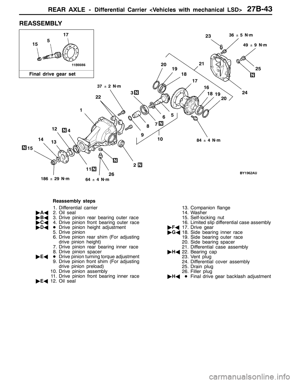
Reassembly steps
1. Differential carrier
"AA2. Oil seal
"BA3. Drive pinion rear bearing outer race
"CA4. Drive pinion front bearing outer race
"DADDrive pinion height adjustment
5. Drive pinion
6. Drive pinion rear shim (For adjusting
drive pinion height)
7. Drive pinion rear bearing inner race
8. Drive pinion spacer
"EADDrive pinion turning torque adjustment
9. Drive pinion front shim (For adjusting
drive pinion preload)
10. Drive pinion assembly
11. Drive pinion front bearing inner race
"EA12. Oil seal13. Companion flange
14. Washer
15. Self-locking nut
16. Limited slip differential case assembly
"FA17. Drive gear
"GA18. Side bearing inner race
19. Side bearing outer race
20. Side bearing spacer
21. Differential case assembly
"HA22. Bearing cap
23. Vent plug
24. Differential cover assembly
25. Drain plug
26. Filler plug
"HADFinal drive gear backlash adjustment
Page 991 of 1449

REAR AXLE -Differential Carrier
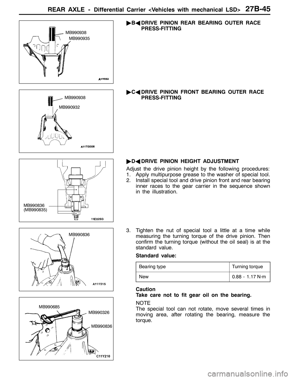
"BADRIVE PINION REAR BEARING OUTER RACE
PRESS-FITTING
"CADRIVE PINION FRONT BEARING OUTER RACE
PRESS-FITTING
"DADRIVE PINION HEIGHT ADJUSTMENT
Adjust the drive pinion height by the following procedures:
1. Apply multipurpose grease to the washer of special tool.
2. Install special tool and drive pinion front and rear bearing
inner races to the gear carrier in the sequence shown
in the illustration.
3. Tighten the nut of special tool a little at a time while
measuring the turning torque of the drive pinion. Then
confirm the turning torque (without the oil seal) is at the
standard value.
Standard value:
Bearing typeTurning torque
New0.88 - 1.17 N·m
Caution
Take care not to fit gear oil on the bearing.
NOTE
The special tool can not rotate, move several times in
moving area, after rotating the bearing, measure the
torque.
MB990938
MB990935
MB990938
MB990932
MB990836
(MB990835)
MB990836
MB990326 MB990685
MB990836
Page 993 of 1449

REAR AXLE -Differential Carrier
3. Measure the drive pinion turning torque (without the oil
seal).
Standard value:
Bearing divisionTurning torque
New0.88 - 1.17 N·m
Caution
Take care not to fit gear oil on the bearing.
4. If the drive pinion turning torque is not within the standard
value, adjust the turning torque by replacing the drive
pinion front shim(s) or the drive pinion spacer.
NOTE
When selecting the drive pinion front shims, if the number
of shims is large, reduce the number of shims to a minimum
by selecting the drive pinion spacers.
Also, select the drive pinion spacer from the following
two types.
Height of drive pinion spacer mmIdentification colour
57.72-
57.08Red
5. Remove the companion flange and drive pinion again.
Then insert the drive pinion front bearing inner race into
the gear carrier. Use special tool to press-fit the oil seal.
6. Install the drive pinion assembly and companion flange
with mating marks properly aligned. Tighten the
companion flange self-locking nut to the specified torque
using special tool.
MB990326
MB990685
Identification
colour
MB990727
MB990850
186±29 N·m
Page 1047 of 1449

BASIC BRAKE SYSTEM -Service Specifications35A-5
SERVICE SPECIFICATIONS
ItemsStandard valueLimit
Brake pedal height mm169.1 - 172.1-
Brake pedal play mm3-8-
Brake pedal to floorboard clearance when the brake pedal is depressed mm90 or more-
Brake booster push rod protrusion amount mm8.98 - 9.23-
Proportioning valve
Split point MPa2.70 - 3.19-
Output fluid pressure MPa 3.68 - 4.17-
Output fluid pressure difference between left and right MPa-0.49
Front disc brake
Pad thickness mm10.02.0
Discthicknessmm24 022 4Discthickness mm24.022.4
Disc run-out mm-0.03
Drag force N51 or less-
Brembo front disc brake
Pad thickness mm10.02.0
Discthicknessmm32 029 8Discthickness mm32.029.8
Disc run-out mm-0.03
Drag force N69 or less-
Rear disc brake
Pad thickness mm10.02.0
Discthicknessmm20 018 4Discthickness mm20.018.4
Disc run-out mm-0.03
Drag force N69 or less-
Brembo rear disc brake
Pad thickness mm9.02.0
Discthicknessmm22 020 4Discthickness mm22.020.4
Disc run-out mm-0.03
Drag force N69 or less-
Front wheel bearing axial play mm-0.06
Rear wheel bearing axial play mm-0.05
Page 1049 of 1449

BASIC BRAKE SYSTEM -On-vehicle Service35A-7
ON-VEHICLE SERVICE
BRAKE PEDAL CHECK AND ADJUSTMENT
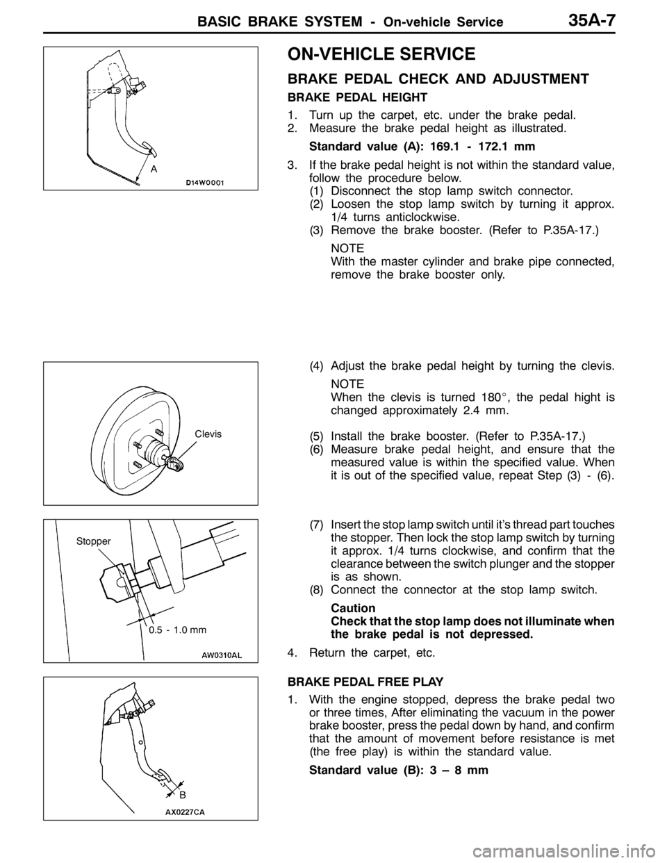
BRAKE PEDAL HEIGHT
1. Turn up the carpet, etc. under the brake pedal.
2. Measure the brake pedal height as illustrated.
Standard value (A): 169.1 - 172.1 mm
3. If the brake pedal height is not within the standard value,
follow the procedure below.
(1) Disconnect the stop lamp switch connector.
(2) Loosen the stop lamp switch by turning it approx.
1/4 turns anticlockwise.
(3) Remove the brake booster. (Refer to P.35A-17.)
NOTE
With the master cylinder and brake pipe connected,
remove the brake booster only.
(4) Adjust the brake pedal height by turning the clevis.
NOTE
When the clevis is turned 180_, the pedal hight is
changed approximately 2.4 mm.
(5) Install the brake booster. (Refer to P.35A-17.)
(6) Measure brake pedal height, and ensure that the
measured value is within the specified value. When
it is out of the specified value, repeat Step (3) - (6).
(7) Insert the stop lamp switch until it’s thread part touches
the stopper. Then lock the stop lamp switch by turning
it approx. 1/4 turns clockwise, and confirm that the
clearance between the switch plunger and the stopper
is as shown.
(8) Connect the connector at the stop lamp switch.
Caution
Check that the stop lamp does not illuminate when
the brake pedal is not depressed.
4. Return the carpet, etc.
BRAKE PEDAL FREE PLAY
1. With the engine stopped, depress the brake pedal two
or three times, After eliminating the vacuum in the power
brake booster, press the pedal down by hand, and confirm
that the amount of movement before resistance is met
(the free play) is within the standard value.
Standard value (B):3–8mm
A
Clevis
Stopper
0.5 - 1.0 mm
B
Page 1050 of 1449

BASIC BRAKE SYSTEM -On-vehicle Service35A-8
2. If the brake pedal play is not within the standard value,
check the following, and adjust or replace if necessary:
DExcessive play between the brake pedal and the clevis
pin, or between the clevis pin and the brake booster
operating rod
DBrake pedal height
DInstallation position of the stop lamp switch, etc.
CLEARANCE BETWEEN BRAKE PEDAL AND FLOOR
BOARD
1. Turn up the carpet etc. under the brake pedal.
2. Start the engine, depress the brake pedal with
approximately 500 N of force, and measure the clearance
between the brake pedal and the floorboard.
Standard value (C): 90 mm or more
3. If the clearance is outside the standard value, check for
air trapped in the brake line and thickness of the disc
brake pad and dragging in the parking brake.
Adjust and replace defective parts as required.
4. Return the carpet, etc.
BRAKE BOOSTER OPERATING TEST
For simple checking of the brake booster operation, carry
out the following tests:
1. Run the engine for one or two minutes, and then stop
it.
If the pedal depresses fully the first time but gradually
becomes higher when depressed succeeding times, the
booster is operating properly. If the pedal height remains
unchanged, the booster is defective.
2. With the engine stopped, step on the brake pedal several
times.
Then start the engine while the brake pedal is stepped
on.
If the pedal moves downward slightly, the booster is in
good condition. If there is no change, the booster is
defective.
3. With the engine running, step on the brake pedal and
then stop the engine.
Hold the pedal depressed for 30 seconds. If the pedal
height does not change, the booster is in good condition.
If the pedal rises, the booster is defective.
If the above three tests are okay, the booster performance
can be determined as good.
If one of the above three tests is not okay at least, the check
valve, vacuum hose, or booster will be defective.
C
Good No good
When engine is
stoppedWhen engine is
started
GoodNo good