Page 79 of 1449

SYNTHETIC-RESIN PARTS -Location of Synthetic-resin PartsE-3
No.Part numberMaterialAbbreviation of
materialHeat-resistant
temperature (_C)
1
2Outside mirror
Rear spoilerAcrylonitrile
Butadiene styreneABS80
3Roof antennaAcrylonitrile
Ethylene butadieneAES90
4HeadlampPolycarbonatePC120
5
6
7Front bumper bezel
Rear door outside handle
Front door outside handlePolycarbonate +
Acrylonitrile butadiene styrenePC + ABS125 - 135
8Splash shieldPolyethylenePE100
9
10
11
12
13
14
15
16
17
18
19
20Oil cooler duct
Instrument panel
Front pillar trim
Inside rear view mirror
Centre pillar trim
Rear pillar trim
Rear door trim
Rear end trim
Rear scuff plate
Rear console box
Front scuff plate
Cowl side trimPolypropylenePP80
21
22
23
24Front bumper extension
Front bumper face
License plate garnish
Front door trimRubber denatured polypropylenePP + E/P80
25Rear bumper faceWith talc added rubber denatured
polypropylenePP + E/P - TD
(HMPP)80 - 100
26Side sill extensionWith 20% talc added rubber dena-
tured polypropylenePP + E/P - TD20
(HMPP)11 0
27Center pillar trim lowerWith 10 % talc added polypropylenePP - TD10
(PPF)110 - 120
28
29Front deck garnish
Floor consoleWith 20 % talc added polypropylenePP - TD20
(PPF)120 - 130
30Hood inlet upper garnishPolyphenylene ether + PolyamidePPE+PA
(PA/PPO)185
31Roof drip moldingPolyvinyl chloridePVC80
NOTE
1. If the new material symbols designated by the ISO differ from the old symbols, both are given, with
the old symbols enclosed in brackets.
ISO: (International Standardization Organization)
2. A slash (/) in the material symbol indicates that two different materials compose a 2-layer construction.
A plus sign (+) indicates that the two different materials are mixed.
3. The material symbols for synthetic-resin parts are embossed on parts in hidden places.
Page 399 of 1449

GENERAL -Supplemental Restraint System (SRS)00-21
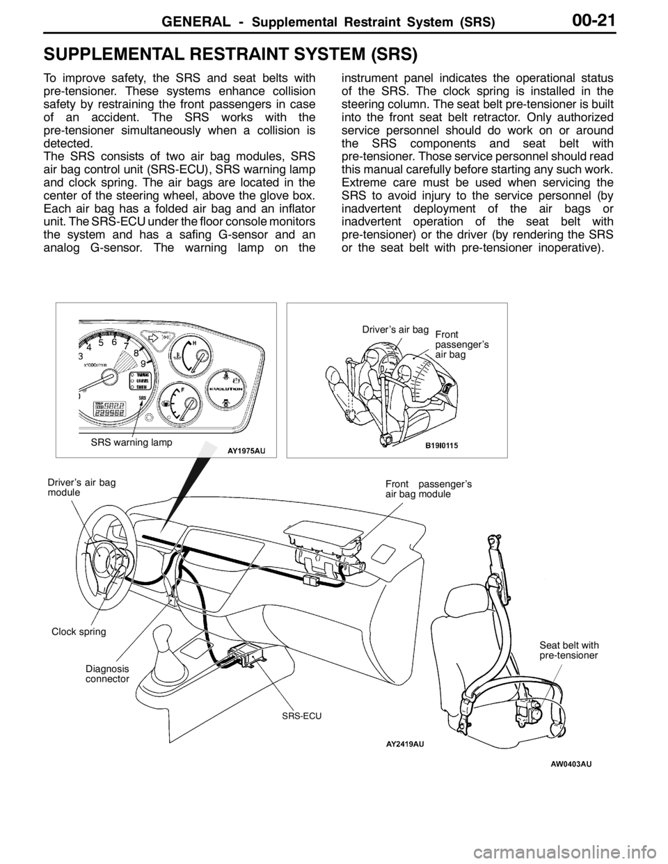
SUPPLEMENTAL RESTRAINT SYSTEM (SRS)
To improve safety, the SRS and seat belts with
pre-tensioner. These systems enhance collision
safety by restraining the front passengers in case
of an accident. The SRS works with the
pre-tensioner simultaneously when a collision is
detected.
The SRS consists of two air bag modules, SRS
air bag control unit (SRS-ECU), SRS warning lamp
and clock spring. The air bags are located in the
center of the steering wheel, above the glove box.
Each air bag has a folded air bag and an inflator
unit. The SRS-ECU under the floor console monitors
the system and has a safing G-sensor and an
analog G-sensor. The warning lamp on theinstrument panel indicates the operational status
of the SRS. The clock spring is installed in the
steering column. The seat belt pre-tensioner is built
into the front seat belt retractor. Only authorized
service personnel should do work on or around
the SRS components and seat belt with
pre-tensioner. Those service personnel should read
this manual carefully before starting any such work.
Extreme care must be used when servicing the
SRS to avoid injury to the service personnel (by
inadvertent deployment of the air bags or
inadvertent operation of the seat belt with
pre-tensioner) or the driver (by rendering the SRS
or the seat belt with pre-tensioner inoperative).
Diagnosis
connectorFront passenger’s
air bag module
Clock spring Driver’s air bag
module
SRS-ECU
SRS warning lamp
Driver’s air bag
Front
passenger’s
air bag
Seat belt with
pre-tensioner
Page 1230 of 1449
INTERIOR -Rear Floor Console52A-12
REAR FLOOR CONSOLE
REMOVAL AND INSTALLATION
1
3 2
2
3
Removal steps
1. Console box mat
2. Rear console assembly
DRear seat cushion assembly
(Refer to P.52A-22.)
DFront scuff plate
(Refer to P.52A-15.)DRear scuff plate (Refer to P.52A-15.)
DCenter pillar trim, lower
(Refer to P.52A-15.)
DFloor carpet
3. Rear console bracket
Page 1235 of 1449
INTERIOR -Trims/Headlining52A-17
REMOVAL SERVICE POINT
AA"FRONT PILLAR TRIM REMOVAL
Release the clip to pull towards the direction shown in the
illustration and remove the front pillar trim.
HEADLINING
REMOVAL AND INSTALLATION
Pre-removal and Post-installation Operation
Removal and Installation of Front Pillar Trim, Center
Pillar Trim, upper, Rear Pillar Trim (Refer to P.52A-15.)
12
3 4 56
45
Removal steps
1. Assist grip
2. Room lamp assembly
3. Front room lamp
AA"4. Sunvisor holder5. Sunvisor assembly
DFront floor console assembly
(Refer to P.52A-10.)
AB"6. Headlining
Section A – A
Front pillar trim
A
AFront pillar trim
Instrument
panel
Page 1246 of 1449

SRS -General InformationSRS -General Information52B-2
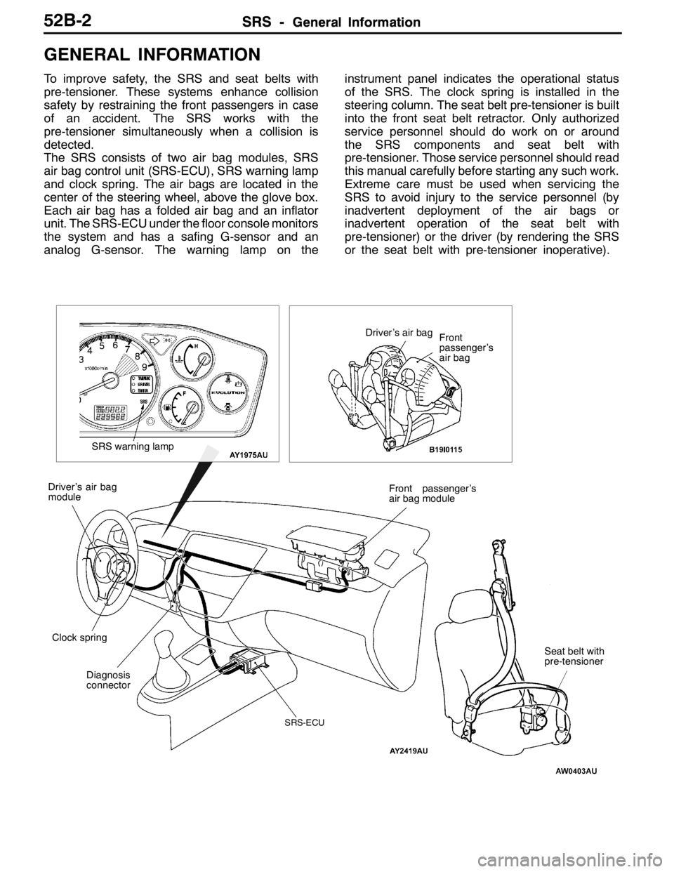
GENERAL INFORMATION
To improve safety, the SRS and seat belts with
pre-tensioner. These systems enhance collision
safety by restraining the front passengers in case
of an accident. The SRS works with the
pre-tensioner simultaneously when a collision is
detected.
The SRS consists of two air bag modules, SRS
air bag control unit (SRS-ECU), SRS warning lamp
and clock spring. The air bags are located in the
center of the steering wheel, above the glove box.
Each air bag has a folded air bag and an inflator
unit. The SRS-ECU under the floor console monitors
the system and has a safing G-sensor and an
analog G-sensor. The warning lamp on theinstrument panel indicates the operational status
of the SRS. The clock spring is installed in the
steering column. The seat belt pre-tensioner is built
into the front seat belt retractor. Only authorized
service personnel should do work on or around
the SRS components and seat belt with
pre-tensioner. Those service personnel should read
this manual carefully before starting any such work.
Extreme care must be used when servicing the
SRS to avoid injury to the service personnel (by
inadvertent deployment of the air bags or
inadvertent operation of the seat belt with
pre-tensioner) or the driver (by rendering the SRS
or the seat belt with pre-tensioner inoperative).
Diagnosis
connectorFront passenger’s
air bag module
Clock spring Driver’s air bag
module
SRS-ECU
SRS warning lamp
Driver’s air bag
Front
passenger’s
air bag
Seat belt with
pre-tensioner
Page 1430 of 1449

HEATER, AIR CONDITIONER AND VENTILATION-Heater Unit and Blower Assembly55-28
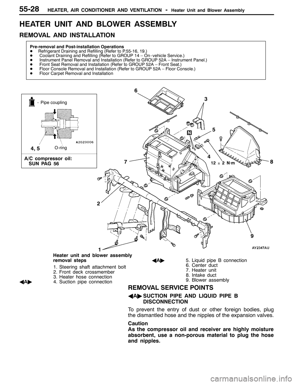
HEATER UNIT AND BLOWER ASSEMBLY
REMOVAL AND INSTALLATION
Pre-removal and Post-installation Operations
DRefrigerant Draining and Refilling (Refer to P.55-16, 19.)
DCoolant Draining and Refilling (Refer to GROUP 14 – On - vehicle Service.)
DInstrument Panel Removal and Installation (Refer to GROUP 52A – Instrument Panel.)
DFront Seat Removal and Installation (Refer to GROUP 52A – Front Seat.)
DFloor Console Removal and Installation (Refer to GROUP 52A – Floor Console.)
DFloor Carpet Removal and Installation
13
5 6
2
12±2 N·m
- Pipe coupling
O-ring
A/C compressor oil:
SUN PAG 56
4, 5
9
7
4
8
Heater unit and blower assembly
removal steps
1. Steering shaft attachment bolt
2. Front deck crossmember
3. Heater hose connection
AA"4. Suction pipe connectionAA"5. Liquid pipe B connection
6. Center duct
7. Heater unit
8. Intake duct
9. Blower assembly
REMOVAL SERVICE POINTS
AA"SUCTION PIPE AND LIQUID PIPE B
DISCONNECTION
To prevent the entry of dust or other foreign bodies, plug
the dismantled hose and the nipples of the expansion valves.
Caution
As the compressor oil and receiver are highly moisture
absorbent, use a non-porous material to plug the hose
and nipples.
Page 1446 of 1449
HEATER, AIR CONDITIONER AND VENTILATION-Ducts55-44
DUCTS
REMOVAL AND INSTALLATION
4
3 5 4
8
76
1 2 3
A
A
Cross-section A - A
Clip
Instrument panel
1
Air outlet removal steps
1. Center air outlet panel
2. Center air outlet
3. Side air outlet
Defroster nozzle and distribution
duct removal steps
DInstrument panel (Refer to GROUP
52A.)
4. Side defroster duct5. Defroster nozzle
6. Distribution duct
Foot duct removal step
DConsole cover and glove box (Refer
to GROUP 52A – Instrument Panel.)
7. Right-hand foot duct
DUnder cover (Refer to GROUP 52A
– Instrument Panel.)
8. Left-hand foot duct