2007 MITSUBISHI LANCER EVOLUTION steering wheel adjustment
[x] Cancel search: steering wheel adjustmentPage 1 of 1449

00
11
12
13
14
15
16
17
21
22
25
26
27
31
32
33
34
35
36
37
42
51
52
54
55
General........................
Engine .........................
Engine Lubrication .............
Fuel ...........................
Engine Cooling .................
Intake and Exhaust ............
Engine Electrical ...............
Engine and Emission Control ....
Clutch .........................
Manual Transmission ...........
Propeller Shaft .................
Front Axle ......................
Rear Axle ......................
Wheel and Tyre .................
Power Plant Mount ..............
Front Suspension ...............
Rear Suspension ...............
Service Brakes .................
Parking Brakes .................
Steering ........................
Body ...........................
Exterior ........................
Chassis Electrical ..............
Electrical Wiring ................
Body Repair ....................
WORKSHOP
MANUAL
FOREWORD
This Workshop Manual contains procedures for
service mechanics, including removal, disassembly,
inspection, adjustment, reassembly and
installation. Use the following manuals in
combination with this manual as required.
TECHNICAL INFORMATION MANUAL N0104CT9A
All information, illustrations and product
descriptions contained in this manual are current
as at the time of publication. We, however, reserve
the right to make changes at any time without prior
notice or obligation.
The EVOLUTION-VII is sold exclusively through
RALLIART Inc. Since the EVOLUTION-VII is a
rally-based model, it will not be warranted and will
not be homologated for general production.
Therefore, any service matters on the
EVOLUTION-VII should be inquired to RALLIART
Inc. as usual.
EMitsubishi Motors Corporation May 2001
Interior and Supplemental
Restraint System (SRS) ........
Heater, Air Conditioner and
Ventilation .....................
Page 1022 of 1449

POWER PLANT MOUNT - Crossmember32-8
CROSSMEMBER
REMOVAL AND INSTALLATION
Caution
1. Before removing the steering wheel and air bag module assembly, always refer to GROUP
52B - Service Precautions, Air bag Module and Clock Spring. Also, set the front wheels so
that they are facing straight forward, and remove the ignition key. If you fail to do this, the
SRS clock spring will be damaged, causing the SRS air bag to be inoperative and serious
injury.
2. *
1: Indicates parts which should be initially tightened, and then fully tightened after placing
the vehicle horizontally and loading the full weight of the engine on the vehicle body.
3. *
2: Indicates parts which should be temporarily tightened, and then fully tightened with the
vehicle on the ground in the unladen condition.
Caution
If the vehicle is equipped the Brembo disc brake, during maintenance, take care not to contact
the parts or tools to the caliper because the paint of caliper will be scratched.
Pre-removal Operations
DUnder Cover Removal
(Refer to GROUP 51 - Front Bumper.)
DCentermember, Crossmember Bar Removal
(Refer to P.32-6.)
DFront Exhaust Pipe Removal
(Refer to GROUP 15.)
DSteering Wheel Air Bag Module Assembly Removal
(Refer to GROUP 37A.)
DPower Steering Fluid Draining
(Refer to GROUP 37A - On-vehicle Service.)Post-installation Operations
DCentermember, Crossmember Bar Installation
(Refer to P.32-6.)
DFront Exhaust Pipe Installation
(Refer to GROUP 15.)
DSteering Wheel Air Bag Module Assembly
Installation (Refer to GROUP 37A.)
DPower Steering Fluid Supplying
(Refer to GROUP 37A - On-vehicle Service.)
DPower Steering Fluid Line Bleeding
(Refer to GROUP 37A - On-vehicle Service.)
DPress the dust cover with a finger to check whether
the dust cover is cracked or damaged.
DChecking Steering Wheel Position with Wheels
Straight Ahead
DFront Wheel Alignment Check and Adjustment
(Refer to GROUP 37A - On-vehicle Service.)
DUnder Cover Installation
(Refer to GROUP 51 - Front Bumper.)
Page 1030 of 1449

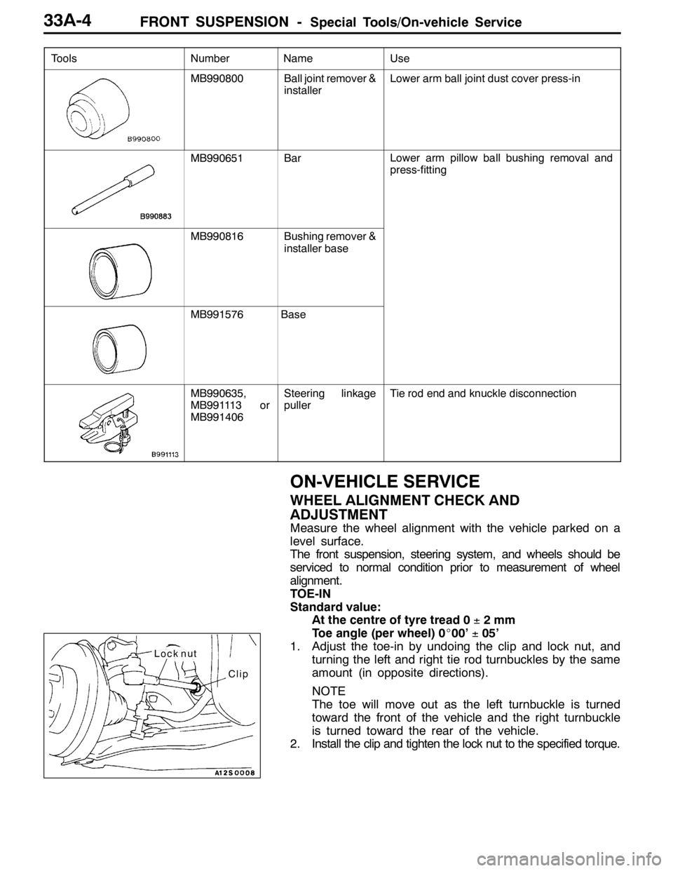
FRONT SUSPENSION -Special Tools/On-vehicle Service33A-4
Tools UseName Number
MB990800Ball joint remover &
installerLower arm ball joint dust cover press-in
MB990651BarLower arm pillow ball bushing removal and
press-fitting
MB990816Bushing remover &
installer base
MB991576Base
MB990635,
MB991113 or
MB991406Steering linkage
pullerTie rod end and knuckle disconnection
ON-VEHICLE SERVICE
WHEEL ALIGNMENT CHECK AND
ADJUSTMENT
Measure the wheel alignment with the vehicle parked on a
level surface.
The front suspension, steering system, and wheels should be
serviced to normal condition prior to measurement of wheel
alignment.
TOE-IN
Standard value:
At the centre of tyre tread 0±2mm
Toe angle (per wheel) 0_00’±05’
1. Adjust the toe-in by undoing the clip and lock nut, and
turning the left and right tie rod turnbuckles by the same
amount (in opposite directions).
NOTE
The toe will move out as the left turnbuckle is turned
toward the front of the vehicle and the right turnbuckle
is turned toward the rear of the vehicle.
2. Install the clip and tighten the lock nut to the specified torque.
Clip
Lock nut
Page 1039 of 1449

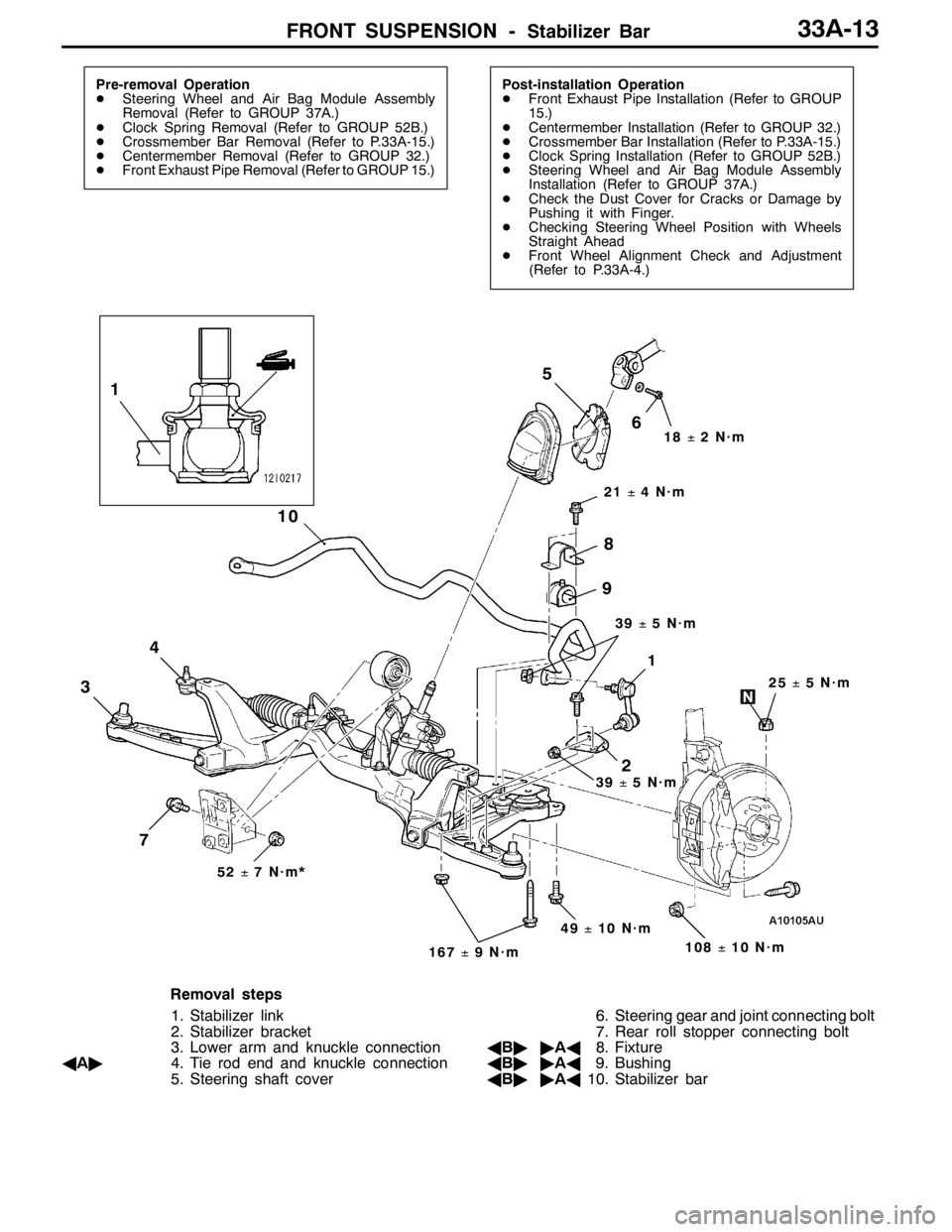
FRONT SUSPENSION -Stabilizer Bar33A-13
Pre-removal Operation
DSteering Wheel and Air Bag Module Assembly
Removal (Refer to GROUP 37A.)
DClock Spring Removal (Refer to GROUP 52B.)
DCrossmember Bar Removal (Refer to P.33A-15.)
DCentermember Removal (Refer to GROUP 32.)
DFront Exhaust Pipe Removal (Refer to GROUP 15.)Post-installation Operation
DFront Exhaust Pipe Installation (Refer to GROUP
15.)
DCentermember Installation (Refer to GROUP 32.)
DCrossmember Bar Installation (Refer to P.33A-15.)
DClock Spring Installation (Refer to GROUP 52B.)
DSteering Wheel and Air Bag Module Assembly
Installation (Refer to GROUP 37A.)
DCheck the Dust Cover for Cracks or Damage by
Pushing it with Finger.
DChecking Steering Wheel Position with Wheels
Straight Ahead
DFront Wheel Alignment Check and Adjustment
(Refer to P.33A-4.)
3
4
10
21±4N·m
51
1
2
25±5N·m
18±2N·m
108±10 N·m
52±7N·m*
49±10 N·m
167±9N·m
7
8
9
6
39±5N·m
39±5N·m
Removal steps
1. Stabilizer link
2. Stabilizer bracket
3. Lower arm and knuckle connection
AA"4. Tie rod end and knuckle connection
5. Steering shaft cover6. Steering gear and joint connecting bolt
7. Rear roll stopper connecting bolt
AB""AA8. Fixture
AB""AA9. Bushing
AB""AA10. Stabilizer bar
Page 1071 of 1449

35B-1
ANTI-SKID
BRAKING SYSTEM
(ABS) <4WD>
CONTENTS
GENERAL INFORMATION 2..................
SERVICE SPECIFICATIONS 3.................
LUBRICANTS Refer to GROUP 35A..........
SEALANT Refer to GROUP 35A..............
SPECIAL TOOLS 4...........................
TROUBLESHOOTING 4.......................
ON-VEHICLE SERVICE 26....................
Brake Pedal Check and Adjustment
Refer to GROUP 35A ..........................
Brake Booster Operating Test
Refer to GROUP 35A ..........................
Check Valve Operation Check
Refer to GROUP 35A ..........................
Bleeding Refer to GROUP 35A..................
Brake Fluid Level Sensor Check
Refer to GROUP 35A ..........................
Disc Brake Pad Check and
Replacement Refer to GROUP 35A..............Disc Brake Rotor Check Refer to GROUP 35A...
Brake Disc Thickness Check
Refer to GROUP 35A ..........................
Brake Disc Run-out Check and Correction
Refer to GROUP 35A ..........................
Wheel Speed Sensor Output Voltage Check
26 ............................................
Hydraulic Unit Check 28........................
Remedy for a Flat Battery 29...................
BRAKE PEDAL Refer to GROUP 35A........
MASTER CYLINDER AND BRAKE
BOOSTER Refer to GROUP 35A............
DISC BRAKE Refer to GROUP 35A..........
HYDRAULIC UNIT AND ABS-ECU 30.........
WHEEL SPEED SENSOR 33..................
G SENSORS AND STEERING WHEEL
SENSOR 35..................................
Page 1119 of 1449

STEERING -Special Tools37A-5
Tool UseName Number
MB991006Preload socketMeasurement of the total pinion torque
MB990326Preload socketMeasurement of the ball joint turning torque
MB990993Power steering oil
pressure gauge
adapter (pump
side)Measurement of oil pressure
MB990994Power steering oil
pressure gauge
adapter (hose
side)
MB990662Oil pressure gauge
assemblyMeasurement of oil pressure
MB991204Torque wrench
socketDAdjustment of rack support
DRemoval of rack support cover
MB990784Ornament removerRemoval of steering wheel cover
MB990803Steering wheel
pullerDisconnection of the steering wheel
MB991199Oil seal and
bearing installerDPress fitting of rack housing bearing
DTo press in the oil seal for the rack