Page 21 of 1449
BODY CONSTRUCTION -Body Construction Characteristics
A
114 13B
13
1517
A-19
Rear Floor Sidemember Reinforcement
1 2 3 4 5 6 7810
912
1314
14
AB
111516
17
18 19
20
21
22
2 22
20
211113
1516
17
1. Trailing arm outer bracket
2. Rear floor sidemember support
3. Trailing arm inner bracket
4. Rear floor sidemember
5. Rear floor crossmember extension
6. Differential mount bulkhead
7. Differential mount reinforcement
8. Pipe
9. Square head bolt
10. Retainer
11. Rear suspension bracket12. Muffler hanger center
13. Rear floor sidemember reinforcement front
14. Muffler hanger rear
15. Rear floor sidemember reinforcement rear
16. Bumper stay reinforcement (RS)
17. Rear floor sidemember extension
18. Rear floor sidemember reinforcement
19. Upper link bracket
20. Toe-control link side reinforcement
21. Toe-control link bracket
22. Rear floor side sill
Page 667 of 1449

MPI -On-vehicle Service13A-135
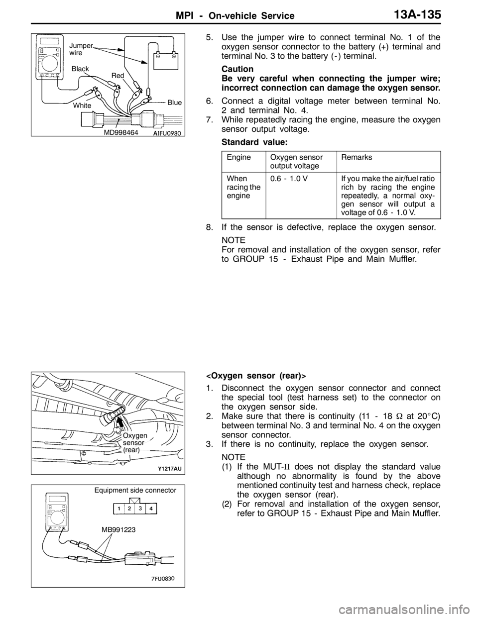
5. Use the jumper wire to connect terminal No. 1 of the
oxygen sensor connector to the battery (+) terminal and
terminal No. 3 to the battery ( - ) terminal.
Caution
Be very careful when connecting the jumper wire;
incorrect connection can damage the oxygen sensor.
6. Connect a digital voltage meter between terminal No.
2 and terminal No. 4.
7. While repeatedly racing the engine, measure the oxygen
sensor output voltage.
Standard value:
EngineOxygen sensor
output voltageRemarks
When
racing the
engine0.6 - 1.0 VIf you make the air/fuel ratio
rich by racing the engine
repeatedly, a normal oxy-
gen sensor will output a
voltage of 0.6 - 1.0 V.
8. If the sensor is defective, replace the oxygen sensor.
NOTE
For removal and installation of the oxygen sensor, refer
to GROUP 15 - Exhaust Pipe and Main Muffler.
1. Disconnect the oxygen sensor connector and connect
the special tool (test harness set) to the connector on
the oxygen sensor side.
2. Make sure that there is continuity (11 - 18Ωat 20_C)
between terminal No. 3 and terminal No. 4 on the oxygen
sensor connector.
3. If there is no continuity, replace the oxygen sensor.
NOTE
(1) If the MUT-IIdoes not display the standard value
although no abnormality is found by the above
mentioned continuity test and harness check, replace
the oxygen sensor (rear).
(2) For removal and installation of the oxygen sensor,
refer to GROUP 15 - Exhaust Pipe and Main Muffler.
MD998464Blue Black
Red
White Jumper
wire
Oxygen
sensor
(rear)
MB991223
Equipment side connector
Page 707 of 1449

15-1
INTAKE AND
EXHAUST
CONTENTS
GENERAL INFORMATION 2..................
SERVICE SPECIFICATION 3..................
SPECIAL TOOL 3............................
ON-VEHICLE SERVICE 3.....................
Turbocharger Supercharging Pressure Check 3...
Supercharging Pressure Control System
Check 4.......................................
Waste Gate Actuator Check 4...................
Waste Gate Solenoid Valve Check 5.............
Air Bypass Valve Check 5......................
Intake Manifold Pressure Check 6...............
Secondary Air Control System Check 6..........
Secondary Air Control Solenoid Valve Check 6...
Secondary Air Valve Check 7...................Vacuum Tank Check 7.........................
AIR CLEANER 8.............................
INTERCOOLER 9............................
INTERCOOLER WATER SPRAY 10............
SECONDARY AIR SUPPLY SYSTEM 14.......
INTAKE MANIFOLD 16.......................
EXHAUST MANIFOLD 19.....................
TURBOCHARGER 22.........................
EXHAUST PIPE AND MAIN MUFFLER 26.....
CATALYTIC CONVERTER
(REFER TO GROUP 17.) ....................
Page 722 of 1449

INTAKE AND EXHAUST -Intake Manifold15-16
INTAKE MANIFOLD
REMOVAL AND INSTALLATION
Pre-removal and Post-installation Operation
DAir Duct Removal and Installation (Refer to P.15-8.)
DStrut Tower Bar Removal and Installation
(Refer to GROUP 42.)
DUnder Cover Removal and Installation
(Refer to GROUP 51 - Front Bumper.)
DEngine Coolant Draining and Supplying
(Refer to GROUP 14 - On-vehicle Service.)
DThrottle Body Removal and Installation (Refer to
GROUP 13A - Throttle Body.)DCrossmember Bar Removal and Installation (Refer
to GROUP 32 - Engine Roll Stopper, Centermember.)
DFront Exhaust Pipe Removal and Installation (Refer
to GROUP 15 - Exhaust Pipe and Main Muffler.)
DSecondary Air Control Valve Bracket Removal and
Installation (Refer to P.15-14.)
DEngine Oil Draining and Supplying
1
2
3 4
5 6 7
8 10
11
1214
13
15
16 17
18
9
11±1 N·m3.0±0.5 N·m
13±1 N·m
(Engine oil)
(Engine oil) 5.0±1.0 N·m
14 8
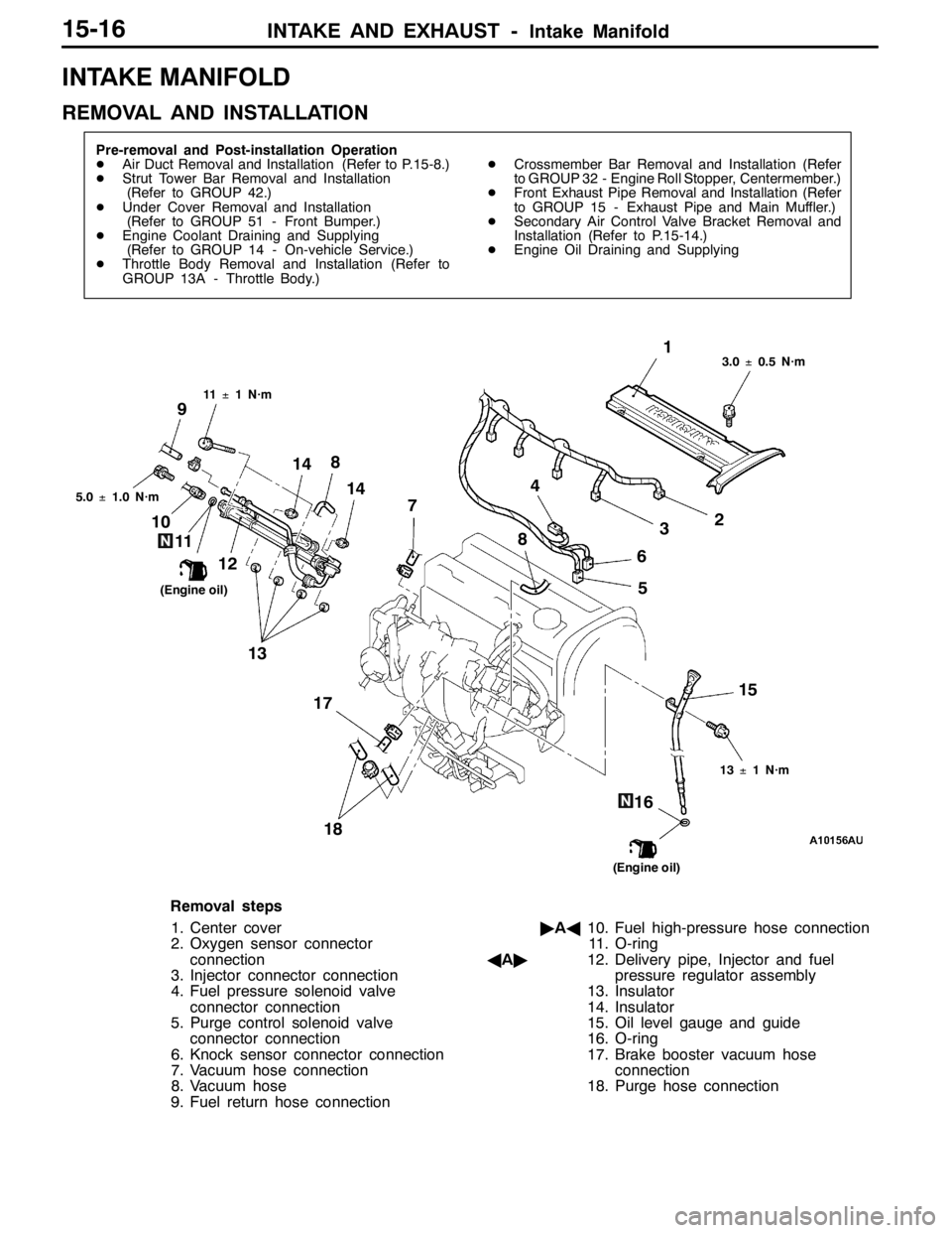
Removal steps
1. Center cover
2. Oxygen sensor connector
connection
3. Injector connector connection
4. Fuel pressure solenoid valve
connector connection
5. Purge control solenoid valve
connector connection
6. Knock sensor connector connection
7. Vacuum hose connection
8. Vacuum hose
9. Fuel return hose connection"AA10. Fuel high-pressure hose connection
11. O-ring
AA"12. Delivery pipe, Injector and fuel
pressure regulator assembly
13. Insulator
14. Insulator
15. Oil level gauge and guide
16. O-ring
17. Brake booster vacuum hose
connection
18. Purge hose connection
Page 732 of 1449
INTAKE AND EXHAUST -Exhaust Pipe and Main Muffler15-26
EXHAUST PIPE AND MAIN MUFFLER
REMOVAL AND INSTALLATION
Pre-removal and Post-installation Operation
DUnder Cover Removal and Installation (Refer to GROUP 51 - Front Bumper.)
DCrossmember Bar Removal and Installation (Refer to GROUP 32 - Engine Roll Stopper, Centermember.)
91
2 3
5
8
11
6 12
10
3
7
12
13±2 N·m
50±5 N·m13±2 N·m49±10 N·m
59±10 N·m13±2 N·m
45±5 N·m4
Exhaust main muffler removal steps
1. Exhaust main muffler
2. Exhaust pipe gasket
3. Exhaust muffler hanger
Center exhaust pipe removal steps
AA"4. Oxygen sensor
5. Center exhaust pipe
2. Exhaust pipe gasket
6. Exhaust pipe gasket
7. Exhaust pipe hangerFront exhaust pipe removal steps
8. Exhaust pipe gasket
9. Spring
10. Front exhaust pipe
11. Seal ring
12. Exhaust pipe hanger
REMOVAL SERVICE POINT
AA"OXYGEN SENSOR REMOVAL
Use special tool to remove the oxygen sensor.
MD998770
Oxygen sensor
Page 857 of 1449

MANUAL TRANSMISSION - Transfer Assembly22A-49
TRANSFER ASSEMBLY
REMOVAL AND INSTALLATION
Pre-removal and Post-installation Operation
DUnder Cover Removal and Installation (Refer to GROUP 51 - Front Bumper.)
DSide Under Cover Removal and Installation
DTransmission Oil Draining and Supplying (Refer to P.22A-40.)
DTransfer Oil Draining and Supplying (Refer to P.22A-40.)
DEngine Coolant Draining and Supplying (Refer to GROUP 14 - On-vehicle Service.)
DCrossmember Bar Removal and Installation (Refer to GROUP 32 - Engine Roll Stopper, Centermember.)
DFront Exhaust Pipe Removal and Installation (Refer to GROUP 15 - Exhaust Pipe and Main Muffler.)
DBattery and Battery Tray Removal and Installation
DAir Cleaner, Air Intake Hose Removal and Installation (Refer to GROUP 15 - Air Cleaner.)
DSecondary Air Hose Removal and Installation (Refer to GROUP 15 - Secondary Air Control System.)
DStrut Tower Bar Removal and Installation (Refer to GROUP 42.)
DAir Hose E, Air By-pass Hose and Air By-pass Valve, Air Pipe C, Air Hose D, Air Pipe B, Air Hose A Removal and
Installation (Refer to GROUP 15 - Intercooler.)
DRadiator Removal and Installation (Refer to GROUP 14.)
DBleeding and Hydraulic Pressure Check (Refer to P.22A-42, 43)
12 3
4
5 6 7
8
25±5 N·m
108±10 N·m
39±5 N·m
39±5 N·m
245±29 N·m
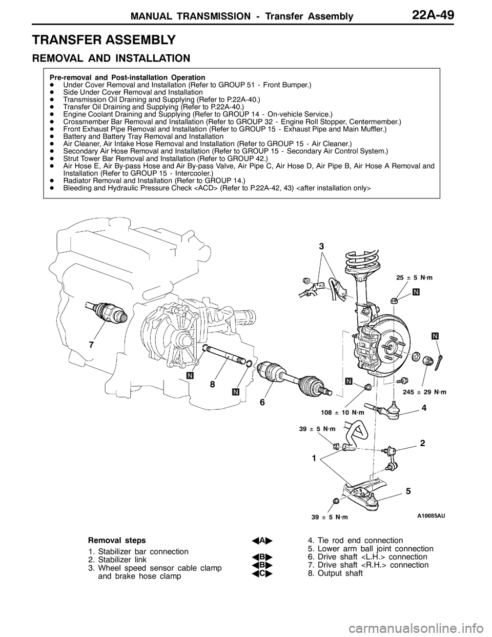
Removal steps
1. Stabilizer bar connection
2. Stabilizer link
3. Wheel speed sensor cable clamp
and brake hose clampAA"4. Tie rod end connection
5. Lower arm ball joint connection
AB"6. Drive shaft connection
AB"7. Drive shaft connection
AC"8. Output shaft