Page 1 of 1449

00
11
12
13
14
15
16
17
21
22
25
26
27
31
32
33
34
35
36
37
42
51
52
54
55
General........................
Engine .........................
Engine Lubrication .............
Fuel ...........................
Engine Cooling .................
Intake and Exhaust ............
Engine Electrical ...............
Engine and Emission Control ....
Clutch .........................
Manual Transmission ...........
Propeller Shaft .................
Front Axle ......................
Rear Axle ......................
Wheel and Tyre .................
Power Plant Mount ..............
Front Suspension ...............
Rear Suspension ...............
Service Brakes .................
Parking Brakes .................
Steering ........................
Body ...........................
Exterior ........................
Chassis Electrical ..............
Electrical Wiring ................
Body Repair ....................
WORKSHOP
MANUAL
FOREWORD
This Workshop Manual contains procedures for
service mechanics, including removal, disassembly,
inspection, adjustment, reassembly and
installation. Use the following manuals in
combination with this manual as required.
TECHNICAL INFORMATION MANUAL N0104CT9A
All information, illustrations and product
descriptions contained in this manual are current
as at the time of publication. We, however, reserve
the right to make changes at any time without prior
notice or obligation.
The EVOLUTION-VII is sold exclusively through
RALLIART Inc. Since the EVOLUTION-VII is a
rally-based model, it will not be warranted and will
not be homologated for general production.
Therefore, any service matters on the
EVOLUTION-VII should be inquired to RALLIART
Inc. as usual.
EMitsubishi Motors Corporation May 2001
Interior and Supplemental
Restraint System (SRS) ........
Heater, Air Conditioner and
Ventilation .....................
Page 813 of 1449

MANUAL TRANSMISSION - Troubleshooting 22A-5
TROUBLESHOOTING
BASIC TROUBLESHOOTING CONDITIONS
Refer to GROUP 00 - How to Use Troubleshooting/Inspection Service Points.
NOTE
Before starting the troubleshooting procedure, make sure that the following items have been checked
okay.
DIs the appropriate steering wheel installed at the center of the steering column shaft correctly?
DAre the tire, wheel size, specifications, air pressure, balance, and wear state normal?
DIs the wheel alignment normal?
DHas the engine, suspension, etc. been remodeled in such a way that it will affect the ACD and AYC
systems?
DIAGNOSIS FUNCTION
READING DIAGNOSIS CODE
Read a diagnosis code by the MUT-IIor ACD mode indicator
lamp. (Refer to GROUP 00 - How to Use Troubleshooting/
Inspection Service Points.)
NOTE
Connect the MUT-IIto the diagnosis connector (16-pin).
ERASING DIAGNOSIS CODES
When using the MUT-II
Connect the MUT-IIto the diagnosis connector (16-pin) and
erase the diagnosis code.
Caution
Turn the ignition switch to the “LOCK”(OFF) position
before connecting or disconnecting the MUT-II.
ACDmode indicator lamp
Page 1038 of 1449

FRONT SUSPENSION -Lower Arm Assembly/Stabilizer Bar33A-12
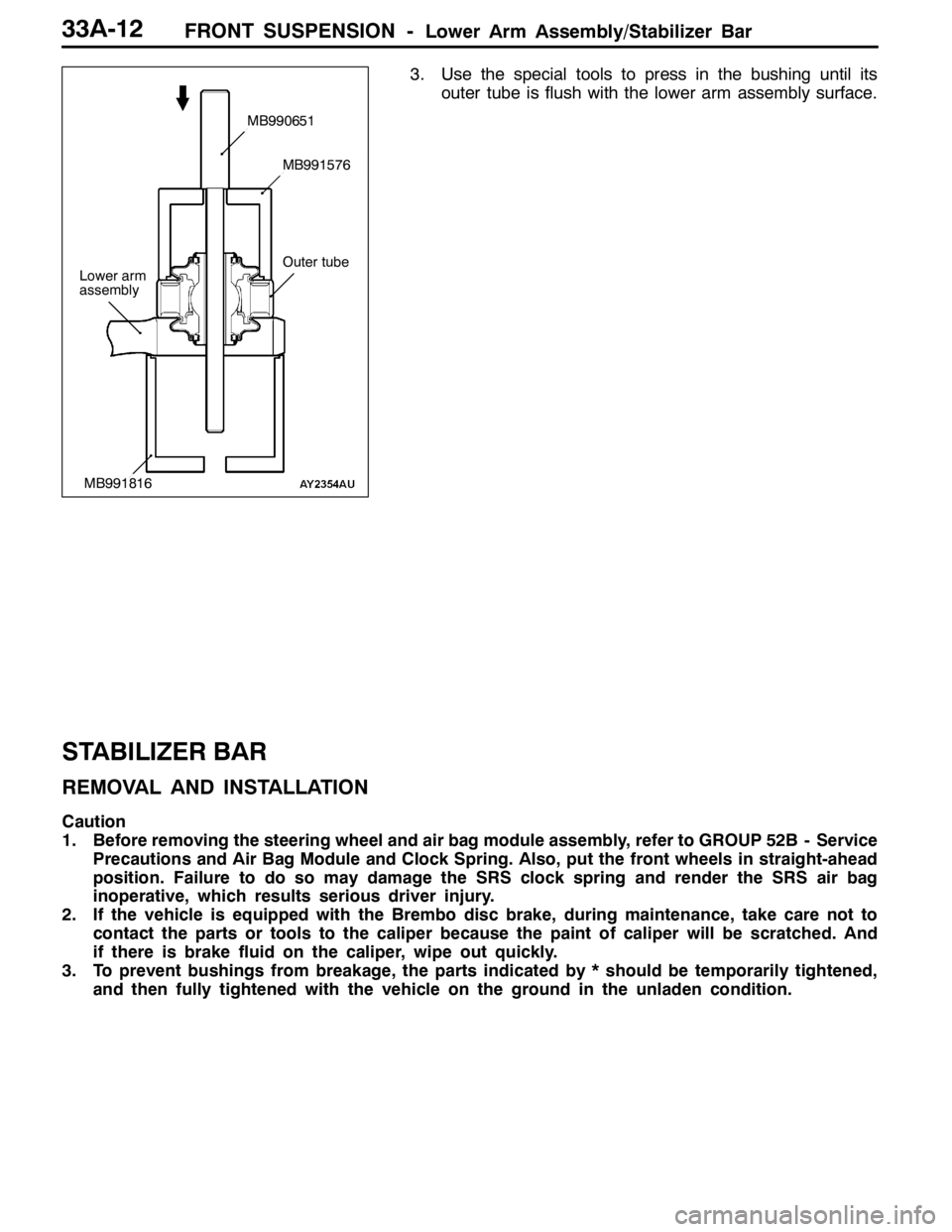
3. Use the special tools to press in the bushing until its
outer tube is flush with the lower arm assembly surface.
STABILIZER BAR
REMOVAL AND INSTALLATION
Caution
1. Before removing the steering wheel and air bag module assembly, refer to GROUP 52B - Service
Precautions and Air Bag Module and Clock Spring. Also, put the front wheels in straight-ahead
position. Failure to do so may damage the SRS clock spring and render the SRS air bag
inoperative, which results serious driver injury.
2. If the vehicle is equipped with the Brembo disc brake, during maintenance, take care not to
contact the parts or tools to the caliper because the paint of caliper will be scratched. And
if there is brake fluid on the caliper, wipe out quickly.
3. To prevent bushings from breakage, the parts indicated by * should be temporarily tightened,
and then fully tightened with the vehicle on the ground in the unladen condition.
Lower arm
assembly
MB990651
MB991576
MB991816
Outer tube
Page 1039 of 1449

FRONT SUSPENSION -Stabilizer Bar33A-13
Pre-removal Operation
DSteering Wheel and Air Bag Module Assembly
Removal (Refer to GROUP 37A.)
DClock Spring Removal (Refer to GROUP 52B.)
DCrossmember Bar Removal (Refer to P.33A-15.)
DCentermember Removal (Refer to GROUP 32.)
DFront Exhaust Pipe Removal (Refer to GROUP 15.)Post-installation Operation
DFront Exhaust Pipe Installation (Refer to GROUP
15.)
DCentermember Installation (Refer to GROUP 32.)
DCrossmember Bar Installation (Refer to P.33A-15.)
DClock Spring Installation (Refer to GROUP 52B.)
DSteering Wheel and Air Bag Module Assembly
Installation (Refer to GROUP 37A.)
DCheck the Dust Cover for Cracks or Damage by
Pushing it with Finger.
DChecking Steering Wheel Position with Wheels
Straight Ahead
DFront Wheel Alignment Check and Adjustment
(Refer to P.33A-4.)
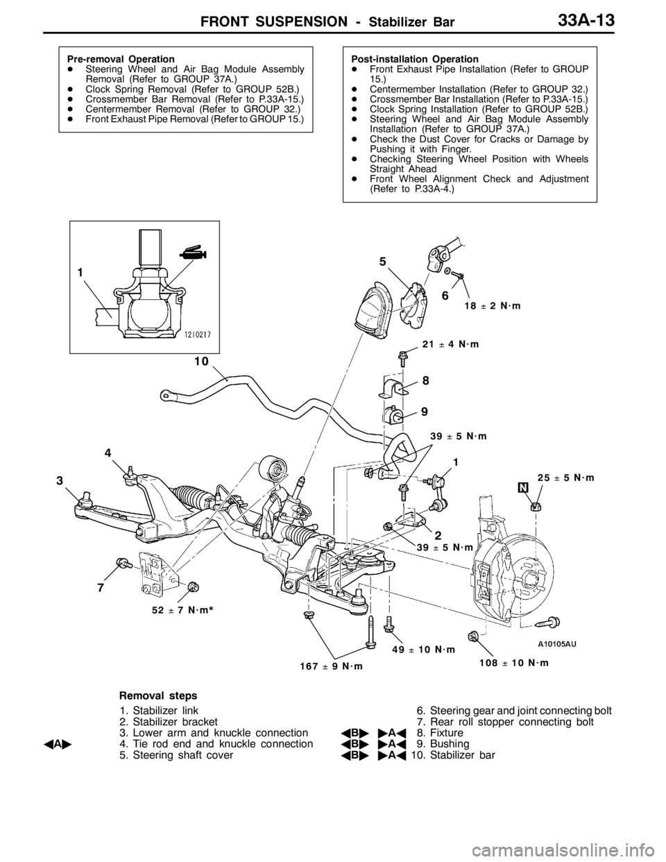
3
4
10
21±4N·m
51
1
2
25±5N·m
18±2N·m
108±10 N·m
52±7N·m*
49±10 N·m
167±9N·m
7
8
9
6
39±5N·m
39±5N·m
Removal steps
1. Stabilizer link
2. Stabilizer bracket
3. Lower arm and knuckle connection
AA"4. Tie rod end and knuckle connection
5. Steering shaft cover6. Steering gear and joint connecting bolt
7. Rear roll stopper connecting bolt
AB""AA8. Fixture
AB""AA9. Bushing
AB""AA10. Stabilizer bar
Page 1090 of 1449

ABS <4WD> -Troubleshooting35B-20
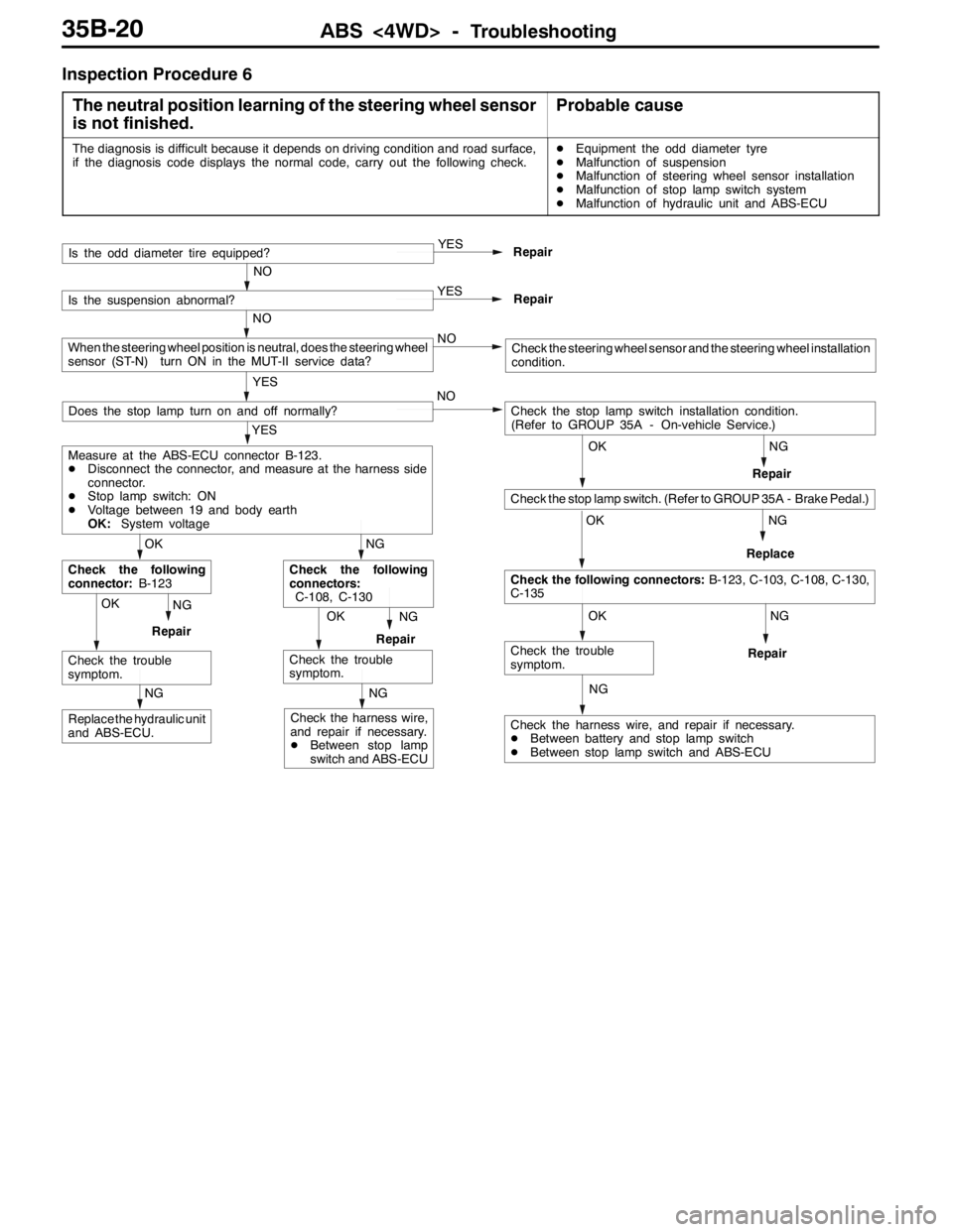
Inspection Procedure 6
The neutral position learning of the steering wheel sensor
is not finished.
Probable cause
The diagnosis is difficult because it depends on driving condition and road surface,
if the diagnosis code displays the normal code, carry out the following check.DEquipment the odd diameter tyre
DMalfunction of suspension
DMalfunction of steering wheel sensor installation
DMalfunction of stop lamp switch system
DMalfunction of hydraulic unit and ABS-ECU
NG
NG
NG
NG
Check the harness wire, and repair if necessary.
DBetween battery and stop lamp switch
DBetween stop lamp switch and ABS-ECU
OK
Check the trouble
symptom.
OK
Check the following connectors:B-123, C-103, C-108, C-130,
C-135
OK
Check the stop lamp switch. (Refer to GROUP 35A - Brake Pedal.)
Check the stop lamp switch installation condition.
(Refer to GROUP 35A - On-vehicle Service.) NO
Repair
OKNG
RepairOKNG
RepairReplace
NG
Replace the hydraulic unit
and ABS-ECU.
NG
Check the harness wire,
and repair if necessary.
DBetween stop lamp
switch and ABS-ECURepair
Check the trouble
symptom.
NG
Check the following
connectors:
C-108, C-130
Check the trouble
symptom.
OK
Check the following
connector:B-123
YES
Measure at the ABS-ECU connector B-123.
DDisconnect the connector, and measure at the harness side
connector.
DStop lamp switch: ON
DVoltage between 19 and body earth
OK:System voltage
Does the stop lamp turn on and off normally?
YES
Repair
NO
Is the odd diameter tire equipped?
YES
Repair
NO
Is the suspension abnormal?
NO
YES
When the steering wheel position is neutral, does the steering wheel
sensor (ST-N) turn ON in the MUT-II service data?Check the steering wheel sensor and the steering wheel installation
condition.