Page 703 of 1449

ENGINE COOLING -Water Hose and Water Pipe/Radiator14-15
REMOVAL SERVICE POINT
AA"RADIATOR UPPER HOSE/RADIATOR LOWER
HOSE DISCONNECTION
After making mating marks on the hose and the hose clamp,
disconnect the hose.
INSTALLATION SERVICE POINTS
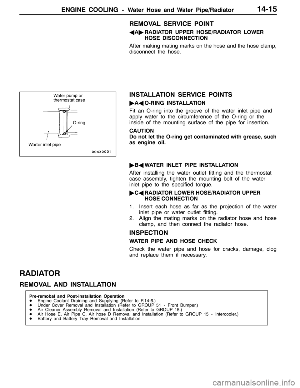
"AAO-RING INSTALLATION
Fit an O-ring into the groove of the water inlet pipe and
apply water to the circumference of the O-ring or the
inside of the mounting surface of the pipe for insertion.
CAUTION
Do not let the O-ring get contaminated with grease, such
as engine oil.
"BAWATER INLET PIPE INSTALLATION
After installing the water outlet fitting and the thermostat
case assembly, tighten the mounting bolt of the water
inlet pipe to the specified torque.
"CARADIATOR LOWER HOSE/RADIATOR UPPER
HOSE CONNECTION
1. Insert each hose as far as the projection of the water
inlet pipe or water outlet fitting.
2. Align the mating marks on the radiator hose and hose
clamp, and then connect the radiator hose.
INSPECTION
WATER PIPE AND HOSE CHECK
Check the water pipe and hose for cracks, damage, clog
and replace them if necessary.
RADIATOR
REMOVAL AND INSTALLATION
Pre-remobal and Post-installation Operation
DEngine Coolant Draining and Supplying (Refer to P.14-6.)
DUnder Cover Removal and Installation (Refer to GROUP 51 - Front Bumper.)
DAir Cleaner Assembly Removal and Installation (Refer to GROUP 15.)
DAir Hose E, Air Pipe C, Air hose D Removal and Installation (Refer to GROUP 15 - Intercooler.)
DBattery and Battery Tray Removal and Installation
Water pump or
thermostat case
O-ring
Warter inlet pipe
Page 724 of 1449

INTAKE AND EXHAUST -Intake Manifold15-18
INSTALLATION SERVICE POINTS
"AAFUEL HIGH-PRESSURE HOSE CONNECTION
1. Apply a drop of new engine oil to the O-ring.
Caution
Be sure not to let engine oil enter the delivery pipe.
2. While turning the injector, high-pressure fuel hose and
fuel pressure regulator to the right and left, install the
delivery pipe, while being careful not to damage the O-ring.
After installing, check that the hose turns smoothly.
3. If it does not turn smoothly, the O-ring may be trapped,
remove the injector, high-pressure fuel hose or fuel
pressure regulator and then re-insert it into the delivery
pipe and check once again.
4. Tighten the high-pressure fuel hose to the specified torque.
Tightening torque: 5.0±1.0 N⋅m
INSPECTION
Check the following points; replace the part if a problem is
found.
INTAKE MANIFOLD CHECK
1. Check for damage or cracking of any part.
2. Check for obstruction of the negative pressure (vacuum)
outlet port, and for obstruction of the water passage or
gas passage.
3. Using a straight edge and thickness gauge, check for
distortion of the cylinder head installation surface.
Standard value: 0.15 mm
Limit: 0.20 mm
Page 730 of 1449

INTAKE AND EXHAUST -Turbocharger15-24
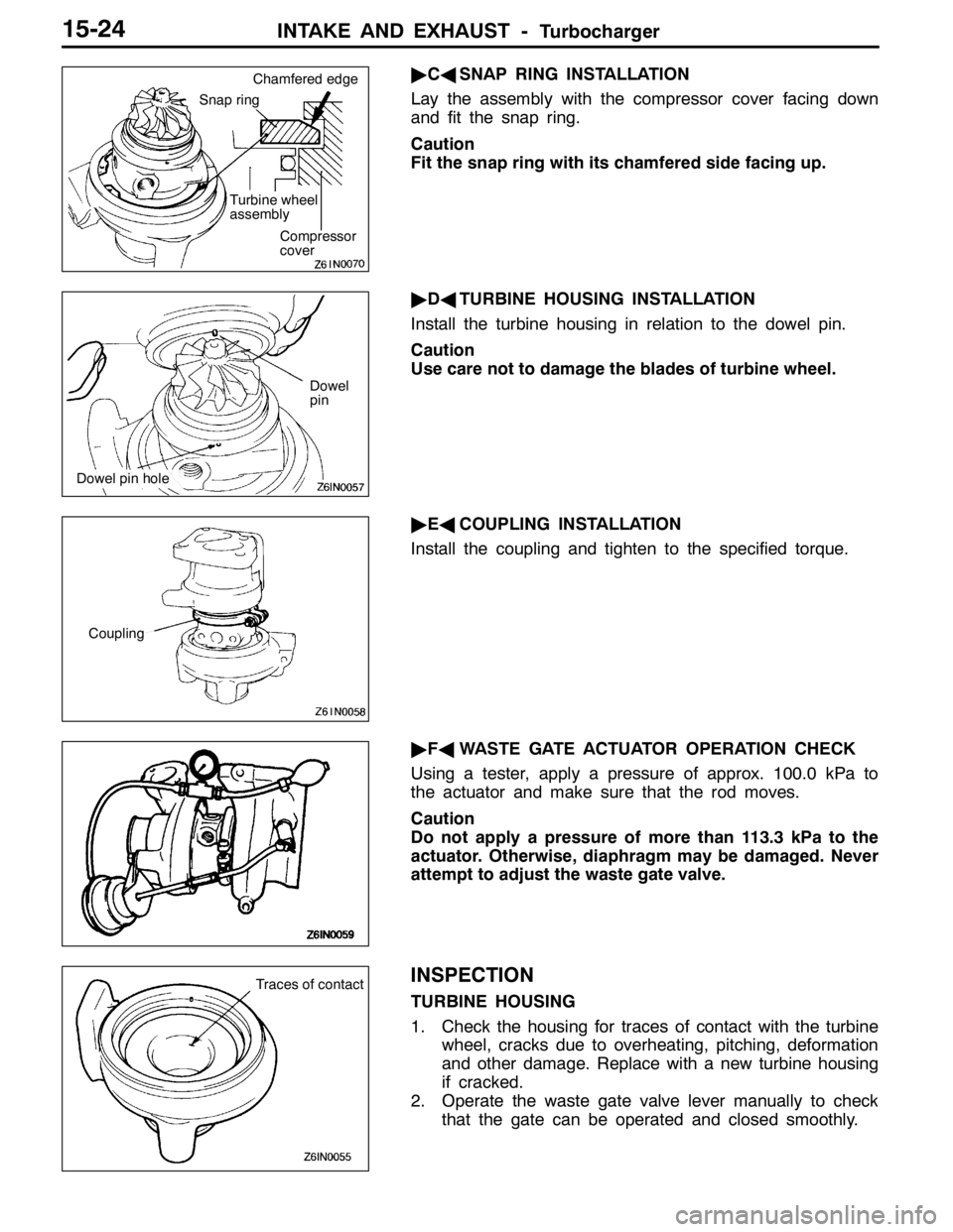
"CASNAP RING INSTALLATION
Lay the assembly with the compressor cover facing down
and fit the snap ring.
Caution
Fit the snap ring with its chamfered side facing up.
"DATURBINE HOUSING INSTALLATION
Install the turbine housing in relation to the dowel pin.
Caution
Use care not to damage the blades of turbine wheel.
"EACOUPLING INSTALLATION
Install the coupling and tighten to the specified torque.
"FAWASTE GATE ACTUATOR OPERATION CHECK
Using a tester, apply a pressure of approx. 100.0 kPa to
the actuator and make sure that the rod moves.
Caution
Do not apply a pressure of more than 113.3 kPa to the
actuator. Otherwise, diaphragm may be damaged. Never
attempt to adjust the waste gate valve.
INSPECTION
TURBINE HOUSING
1. Check the housing for traces of contact with the turbine
wheel, cracks due to overheating, pitching, deformation
and other damage. Replace with a new turbine housing
if cracked.
2. Operate the waste gate valve lever manually to check
that the gate can be operated and closed smoothly.
Snap ring
Turbine wheel
assembly
Compressor
cover Chamfered edge
Dowel
pin
Dowel pin hole
Coupling
Traces of contact
Page 758 of 1449

ENGINE ELECTRICAL -Ignition System16-26
IGNITION SYSTEM
GENERAL INFORMATION
This system is equipped with two ignition coils (A
and B) with built-in power transistors for the No.
1 and No. 4 cylinders and the No. 2 and No. 3
cylinders respectively.
Interruption of the primary current flowing in the
primary side of ignition coil A generates a high
voltage in the secondary side of ignition coil A.
The high voltage thus generated is applied to the
spark plugs of No. 1 and No. 4 cylinders to generate
sparks. At the time that the sparks are generated
at both spark plugs, if one cylinder is at the
compression stroke, the other cylinder is at the
exhaust stroke, so that ignition of the compressed
air/fuel mixture occurs only for the cylinder which
is at the compression stroke.
In the same way, when the primary current flowing
in ignition coil B is interrupted, the high voltage
thus generated is applied to the spark plugs of
No. 2 and No. 3 cylinders.
The Engine-ECU turns the two power transistors
inside the ignition coils alternately on and off. Thiscauses the primary currents in the ignition coils
to be alternately interrupted and allowed to flow
to fire the cylinders in the order 1-3-4-2.
The Engine-ECU determines which ignition coil
should be controlled by means of the signals from
the camshaft position sensor which is incorporated
in the camshaft and from the crank angle sensor
which is incorporated in the crankshaft. It also
detects the crankshaft position in order to provide
ignition at the most appropriate timing in response
to the engine operation conditions. It also detects
the crankshaft position in order to provide ignition
at the most appropriate timing in response to the
engine operation conditions.
When the engine is cold or operated at high
altitudes, the ignition timing is slightly advanced
to provide optimum performance.
When the automatic transmission shifts gears, the
ignition timing is also retarded in order to reduce
output torque, thereby alleviating shifting shocks.
SYSTEM DIAGRAM
Barometric pressure sensor
Intake air temperature sensor
Engine coolant temperature sensor
Camshaft position sensor
Crank angle sensor
Ignition switch - ST
Vehicle speed signalEngine-ECU
Ignition coil A
Ignition coil B Ignition switch
Spark plugBattery
To tachometerCylinder No. Air flow sensor
1 4
23
Detonation sensor
Page 772 of 1449

ENGINE AND EMISSION CONTROL -Engine Control System17-2
ENGINE CONTROL SYSTEM
GENERAL INFORMATION
A cable-type accelerator mechanism and a
suspended-type pedal have been adopted.
SERVICE SPECIFICATIONS
ItemsStandard value
Accelerator cable play mm1-2
Engineidlespeedr/min850±50Engineidle speed±/min850±50
ON-VEHICLE SERVICE
ACCELERATOR CABLE CHECK AND
ADJUSTMENT
1. Turn A/C and lamps OFF.
Inspect and adjust at no load.
2. Warm engine until stabilized at idle.
3. Confirm idle speed is at prescribed value.
Standard value: 850±50 r/min
4. Stop engine (ignition switch OFF).
5. Confirm there are no sharp bends in accelerator cable.
6. Check inner cable for correct slack.
Standard value: 1 - 2 mm
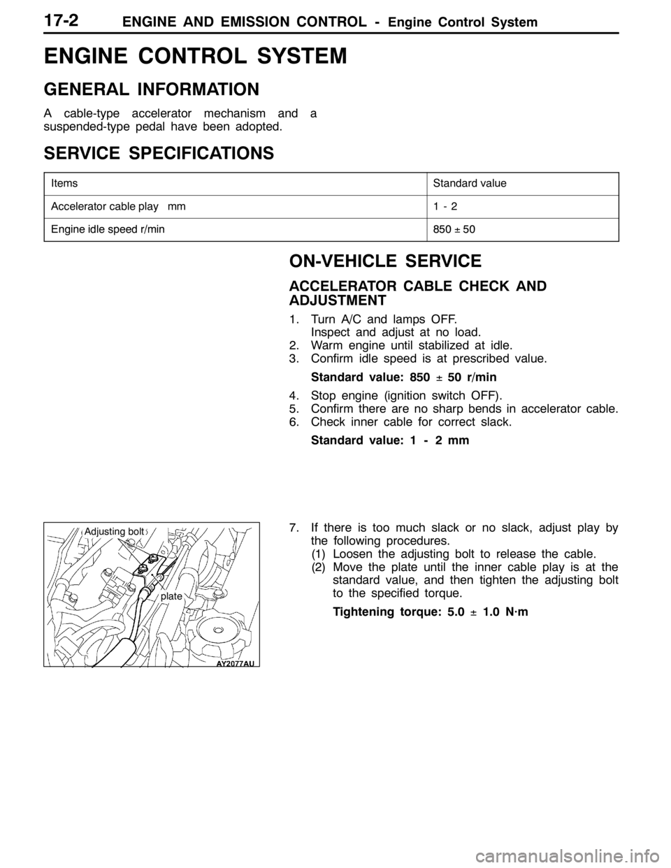
7. If there is too much slack or no slack, adjust play by
the following procedures.
(1) Loosen the adjusting bolt to release the cable.
(2) Move the plate until the inner cable play is at the
standard value, and then tighten the adjusting bolt
to the specified torque.
Tightening torque: 5.0±1.0 N·m
plate
Adjusting bolt
Page 785 of 1449

ENGINE AND EMISSION CONTROL -Emission Control System17-15
EGR VALVE CHECK
1. Remove the EGR valve and inspect for sticking, carbon
deposits, etc. If found, clean with a suitable solvent so
that the valve seats correctly.
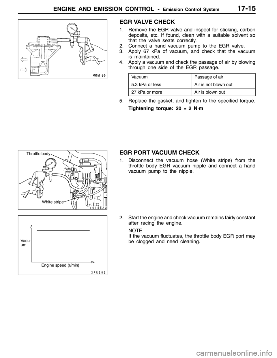
2. Connect a hand vacuum pump to the EGR valve.
3. Apply 67 kPa of vacuum, and check that the vacuum
is maintained.
4. Apply a vacuum and check the passage of air by blowing
through one side of the EGR passage.
VacuumPassage of air
5.3 kPa or lessAir is not blown out
27 kPa or moreAir is blown out
5. Replace the gasket, and tighten to the specified torque.
Tightening torque: 20±2 N·m
EGR PORT VACUUM CHECK
1. Disconnect the vacuum hose (White stripe) from the
throttle body EGR vacuum nipple and connect a hand
vacuum pump to the nipple.
2. Start the engine and check vacuum remains fairly constant
after racing the engine.
NOTE
If the vacuum fluctuates, the throttle body EGR port may
be clogged and need cleaning.
White stripe
Throttle body
Vacu-
um
Engine speed (r/min)
Page 801 of 1449
21B-1
CLUTCH
OVERHAUL
CONTENTS
GENERAL DESCRIPTION 2...................
SPECIFICATIONS 2..........................
SERVICE SPECIFICATIONS 2.................
TIGHTENING TORQUE 2.....................LUBRICANTS 2..............................
CLUTCH 3...................................
CLUTCH RELEASE CYLINDER 6.............
Page 802 of 1449

CLUTCH OVERHAUL -General Description/Specifications/Service Specifications/
Tightening Torque/Lubricants21B-2
GENERAL DESCRIPTION
The pull-type clutch has been adopted to improve the cut-off at high rotations and reduce the clutch
pedal pressing force.
SPECIFICATIONS
Clutch discTypeDry single-disc type
Facing dimension mm240×160
Clutch coverTypeDiaphragm spring, pull-type
Set load N9,320
Clutch control methodHydraulic method
SERVICE SPECIFICATIONS
ItemsLimit value mm
Clutch disc facing rivet sink0.3
Clearance between release cylinder inner diameter and
piston outer diameter0.15
TIGHTENING TORQUE
ItemsTorque N•m
Clutch tube flare nut15±2
Clutch fluid line bracket mounting bolt18±3
Clutch release cylinder air breather11±1
Clutch release cylinder mounting bolt18±3
Clutch release fork shaft mounting bolt9.8±2
Clutch release cylinder union bolt22±2
LUBRICANTS
ItemsSpecified lubricants
Release fork and release cylinder push rod contact sectionMITSUBISHI genuine grease Part No.0101011
orequivalent
Release fork and release fork shaft sliding section
or equivalent
Release fork and release bearing contact section
Piston and piston cup circumferenceMITSUBISHI genuine brake fluid
“
DIA QUEENBRAKEFLUIDSUPER4”
Release cylinder inner circumference
“DIA-QUEENBRAKEFLUIDSUPER4”
or equivalent