2007 MITSUBISHI LANCER EVOLUTION torque
[x] Cancel search: torquePage 839 of 1449

MANUAL TRANSMISSION - Troubleshooting
INSPECTION CHART FOR TROUBLE SYMPTOMS
Trouble symptomInspection
procedure No.Reference
page
No communication possible between MUT-IIand all systems.122A-31
No communication possible between MUT-IIand 4WD-ECU.222A-32
ACD mode indicator lamp does not light up when the ignition switch is set to ”ON“
(engine is stopped).322A-33
More than two ACD mode indicator lamps remain lit even after the engine is started422A-34
The ACD does not operate (no diagnostic code).522A-34
The AYC does not operate (no diagnostic code).6Refer to
GROUPThe rear tire sounds when turning at low speed corners (vehicle slows down)7GROUP
27B.
Noise is produced from the torque transfer differential during turning.8
27B.
INSPECTION PROCEDURES FOR TROUBLE SYMPTOMS
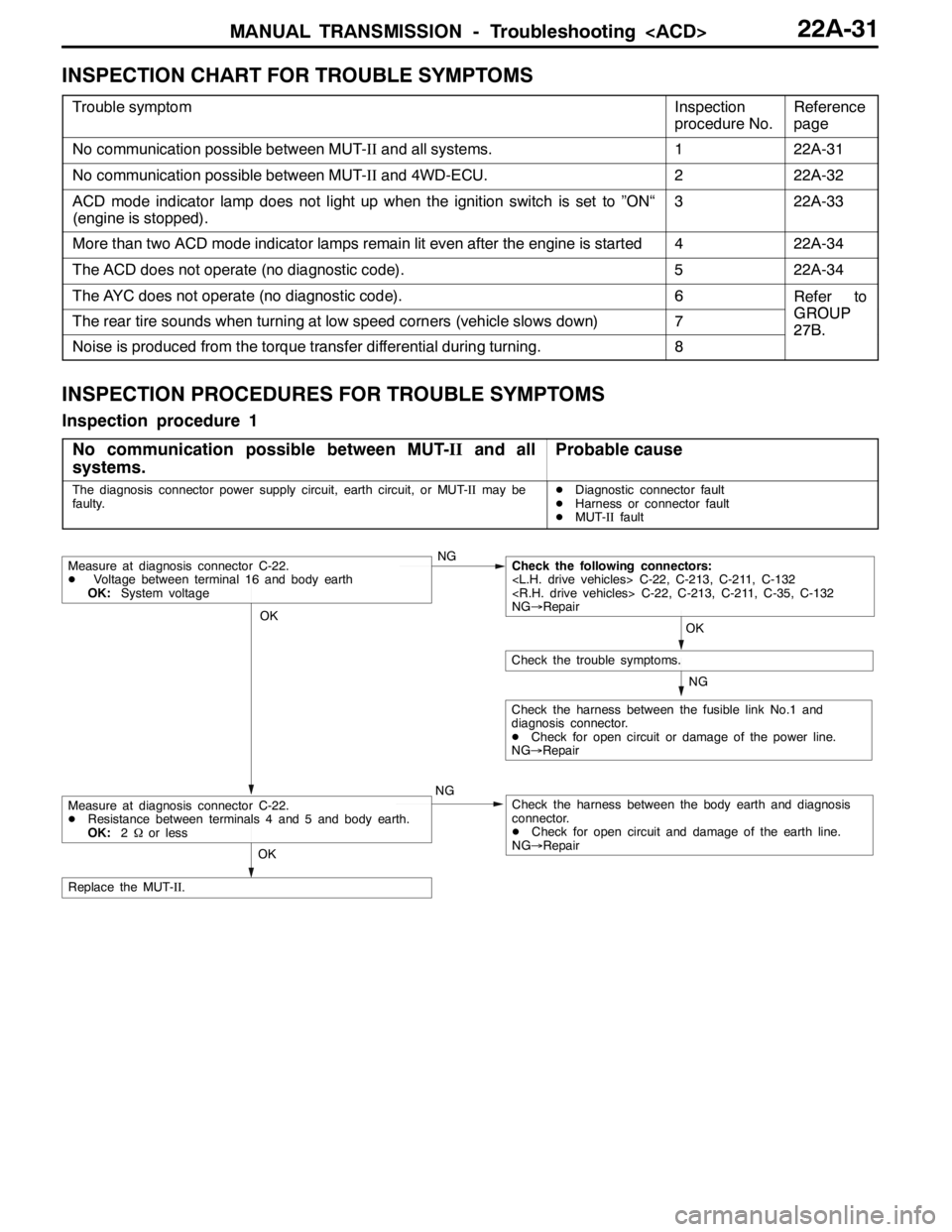
Inspection procedure 1
No communication possible between MUT-IIand all
systems.
Probable cause
The diagnosis connector power supply circuit, earth circuit, or MUT-IImay be
faulty.DDiagnostic connector fault
DHarness or connector fault
DMUT-IIfault
OK
NG
NG
Check the harness between the fusible link No.1 and
diagnosis connector.
DCheck for open circuit or damage of the power line.
NG→Repair
OK
Check the trouble symptoms.
Measure at diagnosis connector C-22.
DVoltage between terminal 16 and body earth
OK:System voltageNGCheck the following connectors:
NG→Repair
Check the harness between the body earth and diagnosis
connector.
DCheck for open circuit and damage of the earth line.
NG→Repair
OK
Replace the MUT-II.
Measure at diagnosis connector C-22.
DResistance between terminals 4 and 5 and body earth.
OK:2Ωor less
Page 845 of 1449

MANUAL TRANSMISSION - Troubleshooting
ACTUATOR TEST JUDGEMENT VALUE
Item
no.Check itemTest descriptionNormal state
01Bleeding
according to the steering angle, and operate
the Proportional valve for five minutes.Make sure no air leaks from the bleeder
screw on the transfer.
02Bleeding
according to the steering angle, and operate
the directional valve for five minutes.Make sure no air leaks from the bleeder
screw on the torque transfer differential.
03Check the oil vol-
umeOperate the directional valve to the left and
right for 20 seconds.Check that the oil volume of the reservoir
tank is appropriate.
04Electric pump
driveOperate the electric pump for 5 seconds.Operation sounds of the electric pump
can be heard.
05Check the opera-
tions of the ACDOperate the Proportional valve
supply the maximum oil pressure to the multi
plate clutch.9Generate the tight corner braking
phenomenon.
06Check clutch op-
erations
maximum oil pressure to the left clutch.When the wheels are lifted, speed
difference will occur between the rear
left and right wheels.
07Check clutch op-
erations
maximum oil pressure to the right clutch.When the wheels are lifted, speed
difference will occur between the rear
left and right wheels.
08Control OFFTurn OFF the electric pump relay, and turn
OFF the control of the ACD and AYC.In actual driving, there is difference
between control ON and OFF.
(1) The actuator test can be executed only when all the following conditions are satisfied.
DAll wheel speed sensor inputs below 20 km/h
DNo system malfunction detected
DSteering angle is within±30 degrees from the neutral position
(2) When the actuator test corresponds to one of the following conditions, forced driving will be cleared.
DWhen any one of the wheel speed sensor input is detected to be above 20 km/h (excluding
Item No.08 “Control OFF”.)
DWhen system malfunction is detected (excluding diagnostic code No.82, 84, and 85)
DWhen the forced drive time is exceeded
DWhen the MUT-IIis removed
DWhen the Clear key of the MUT-IIis operated
Page 848 of 1449

MANUAL TRANSMISSION - On-vehicle Service MANUAL TRANSMISSION - On-vehicle Service22A-40
ON-VEHICLE SERVICE
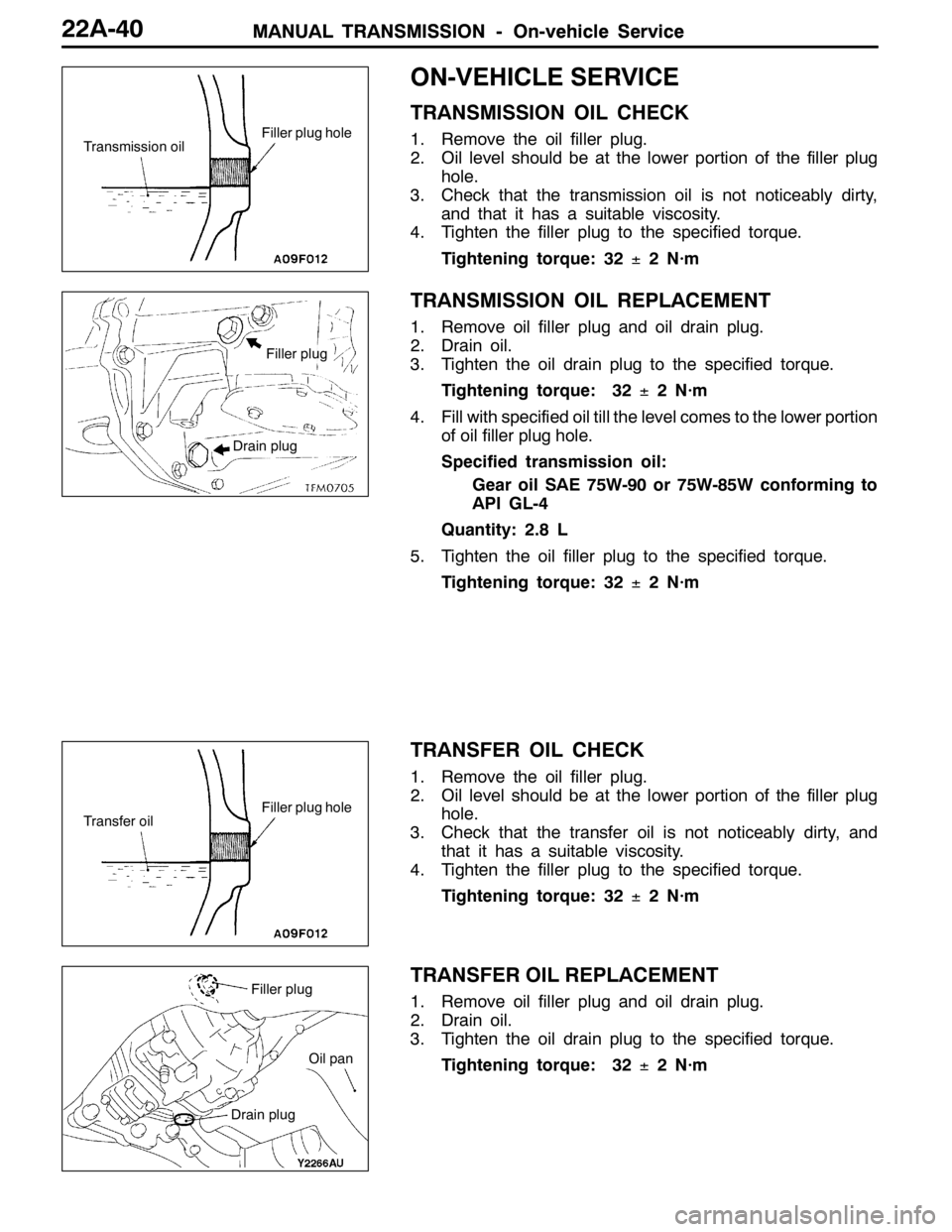
TRANSMISSION OIL CHECK
1. Remove the oil filler plug.
2. Oil level should be at the lower portion of the filler plug
hole.
3. Check that the transmission oil is not noticeably dirty,
and that it has a suitable viscosity.
4. Tighten the filler plug to the specified torque.
Tightening torque: 32±2 N·m
TRANSMISSION OIL REPLACEMENT
1. Remove oil filler plug and oil drain plug.
2. Drain oil.
3. Tighten the oil drain plug to the specified torque.
Tightening torque: 32±2 N·m
4. Fill with specified oil till the level comes to the lower portion
of oil filler plug hole.
Specified transmission oil:
Gear oil SAE 75W-90 or 75W-85W conforming to
API GL-4
Quantity: 2.8 L
5. Tighten the oil filler plug to the specified torque.
Tightening torque: 32±2 N·m
TRANSFER OIL CHECK
1. Remove the oil filler plug.
2. Oil level should be at the lower portion of the filler plug
hole.
3. Check that the transfer oil is not noticeably dirty, and
that it has a suitable viscosity.
4. Tighten the filler plug to the specified torque.
Tightening torque: 32±2 N·m
TRANSFER OIL REPLACEMENT
1. Remove oil filler plug and oil drain plug.
2. Drain oil.
3. Tighten the oil drain plug to the specified torque.
Tightening torque: 32±2 N·m
Transmission oilFiller plug hole
Filler plug
Drain plug
Transfer oilFiller plug hole
Filler plug
Drain plug
Oil pan
Page 849 of 1449

MANUAL TRANSMISSION - On-vehicle Service22A-41
4. Fill with specified oil till the level comes to the lower portion
of oil filler plug hole.
Specified transfer oil:
MITSUBISHI Genuine Gear Oil Part No.8149630
EX, CASTROL HYPOY LS (GL-5, SAE 90),
SHELL-LSD (GL-5, SAE 80W - 90) or equivalent
Quantity:
0.55 L
0.6 L
5. Tighten the oil filler plug to the specified torque.
Tightening torque: 32±2 N·m
FLUID CHECK
1. Remove the maintenance lid located in the luggage
compartment.
2.
If the vehicle has been run, leave it for 90 min. or more
in an ordinary temperature (10_C–30_C) to allow the
accumulator internal pressure to drop.
NOTE
If the ambient temperature is 10_C or less, allow more
time to leave the vehicle to stand idle.
Set the MUT-IIto the 16-pin diagnosis connector. Turn ON
the ignition switch, perform MUT-IIactuator test (Item
No.03), forcibly drive the hydraulic unit and remove the
pressure in the accumulator.
Caution
Turn the ignition switch to the “LOCK”(OFF) position
before connecting or disconnecting the MUT-II.
NOTE
(1) In the actuator test (Item No. 03: Oil Level Check
Mode), the directional valve of the hydraulic unit is
moved to the left and right for 20 times, and then
the differential is cleared automatically. Drive can also
be cleared forcibly using the Clear key of the MUT-II.
(2) If the function has been stopped by fail-safe, the
hydraulic unit cannot be cleared forcibly.
3. Check that the fluid level in the oil reservoir is in the
range between MAX and MIN.
4. If the fluid level is lower than MIN, add the specified
fluid.
Specified fluid: Dia Queen ATF SP III
5. Reinstall the maintenance lid.
Page 850 of 1449

MANUAL TRANSMISSION - On-vehicle Service22A-42
BLEEDING
1. Lift up the vehicle.
2. Set the MUT-IIto the 16-pin diagnosis connector.
Caution
Turn the ignition switch to the “LOCK”(OFF) position
before connecting or disconnecting the MUT-II.
3. Turn the ignition switch to the “ON” position.
4. Set the steering wheel in the straight-ahead position.
5. Perform the MUT-IIactuator test (Item No.02), and forcibly
drive the hydraulic unit.
NOTE
(1) The actuator test (Item No.01: Bleeding Mode) will
be performed for 5 minutes, after which it will be
cleared automatically. Drive can also be cleared during
forced driving using the clear key of the MUT-II.
(2) If the hydraulic unit function has been stopped by
fail-safe, the hydraulic unit cannot be forcibly driven.
6. Remove the cap of the bleeder screw on the transfer,
and connect the vinyl hose.
7
.Slowly turn the steering wheel to the left or right from
the neutral state. Loosen the bleeder screw, and check
that air is discharged together with the fluid.
8
.After the air is discharged, tighten the bleeder screw,
and return the steering wheel to the neutral state.
Caution
During bleeding, replenish the fluid so that some
always remains in the oil reservoir.
9. Repeat steps 6 and 7 several 2 to 3 times, and after
checking that no more air mixes in, tighten the bleeder
screw at the specified torque.
Tightening torque: 5±1 N·m
10. After bleeding, check the fluid level. (Refer to P. 22A-41.)
Caution
If bleeding is not performed completely, noise may
be produced from the hydraulic unit, or the durability
of the pump, etc. may drop.
11. On vehicles with AYC, perform bleeding when the
hydraulic unit is removed. (Refer to GROUP 27B -
On-vehicle Service.)
ACD OPERATION CHECK
1. Lift up the vehicle.
2
.Set the MUT-IIto the 16-pin diagnosis connector.
Caution
Turn the ignition switch to the “LOCK”(OFF) position
before connecting or disconnecting the MUT-II.
3. Start the engine.
Bleeder screw
Front exhaust pipe
Page 852 of 1449

MANUAL TRANSMISSION - On-vehicle Service22A-44
(2) If the hydraulic unit function has been stopped by
fail-safe, the hydraulic unit cannot be forcibly driven.
6. Check that the generated oil pressure of the hydraulic
unit satisfies the standard value.
Standard value: 1.0 – 1.6 MPa
Caution
While the oil pressure is checked, add fluid as
necessary to ensure that it is left in the oil reservoir
during the entire procedure.
7. If the measured value exceeds the standard value, replace
the hydraulic unit.
8. Connect the hydraulic unit and transfer connector
assembly, and tighten the flare nut at the specified torque.
Tightening torque: 34±5 N·m (when screw is dry)
26±4 N·m (when screw is applied with oil)
9. Supply the specified fluid up to the MAX level of the
oil reservoir, and bleed the oil pressure pipes.
Specified fluid: DIA QUEEN ATF SP III
Quantity:
0.9 dm
3
1.0 dm3
WHEEL SPEED SENSOR OUTPUT VOLTAGE
MEASUREMENT
1. Lift the vehicle, and release the parking brake.
2. Disconnect the 4WD-ECU connector, and measure at
the connector of the harness.
Caution
Insert the probe from the harness of the connector.
Inserting in the terminal side may cause contact fault.
3. Rotate the measured wheel by about 1/2 to 1
rotations/second, and check the output voltage between
the following terminals using a circuit tester (AC mV range)
or oscilloscope.
Terminal No.
Front leftFront rightRear leftRear right
6987
19222120
Page 867 of 1449

22B-1
MANUAL
TRANSMISSION
OVERHAUL
CONTENTS
GENERAL DESCRIPTION 2...................
SPECIFICATIONS 6..........................
SERVICE SPECIFICATIONS 6.................
SEALANTS 7................................
LUBRICANTS 8..............................
SNAP RINGS, SPACERS AND THRUST
PLATES FOR ADJUSTMENT 9................
TIGHTENING TORQUE 11....................
SPECIAL TOOLS 12..........................
TRANSMISSION 15...........................
INPUT SHAFT 22............................OUTPUT SHAFT 29..........................
REVERSE IDLER GEAR 37...................
SPEEDOMETER GEAR 38....................
SELECT LEVER 39...........................
CONTROL HOUSING 40......................
CLUTCH HOUSING 43........................
TRANSMISSION CASE 46....................
CENTER DIFFERENTIAL 48..................
TRANSFER 51...............................
Page 877 of 1449

MANUAL TRANSMISSION OVERHAUL -Tightening Torque22B-11
TIGHTENING TORQUE
TRANSMISSION
ItemsTightening torque N•m
Under cover mounting bolt6.9±1
Interlock plate bolt30±3
Clutch housing and transmission case tightening bolt44±5
Clutch release bearing retainer mounting bolt9.8±2
Control housing mounting bolt18±3
Shift cable bracket mounting bolt18±3
Speedometer gear mounting bolt3.9±1
Stopper bracket mounting bolt18±3
Select lever mounting bolt18±3
Select lever mounting nut11±1
Center differential drive gear mounting bolt132±5
Backup light switch32±2
Poppet spring32±2
Reverse idler gear shaft mounting bolt48±5
Roll stopper bracket mounting bolt69±9
TRANSFER
ItemsTightening torque N•m
Transfer cover mounting bolt23±3
Transmission and transfer tightening bolt69±9