2007 MITSUBISHI LANCER EVOLUTION torque
[x] Cancel search: torquePage 379 of 1449

00-1
GENERAL
CONTENTS
HOW TO USE THIS MANUAL 2..............
Scope of Maintenance, Repair and Servicing
Explanations 2.................................
Indication of Destination 2......................
Definition of Terms 2...........................
Indication of Tightening Torque 2................
Model Indications 3............................
Explanation of Manual Contents 4...............
HOW TO USE
TROUBLESHOOTING/INSPECTION SERVICE
POINTS 6....................................
Troubleshooting Contents 6.....................
Diagnosis Function 7...........................
How to Use the Inspection Procedures 10........
Connector Measurement Service Points 11.......
Connector Inspection 12........................
Inspection Service Points for a Blown Fuse 13...
Points to Note for Intermittent Malfunctions 13....
VEHICLE IDENTIFICATION 14.................
Vehicle Information Code Plate 14...............Models 14.....................................
Model Code 15................................
Chassis Number 16............................
Engine Model Number 16.......................
MAJOR SPECIFICATIONS 17.................
PRECAUTIONS BEFORE SERVICE 18.........
SUPPLEMENTAL RESTRAINT SYSTEM
(SRS) 21...................................
SRS SERVICE PRECAUTIONS 22.............
SUPPORT LOCATIONS FOR LIFTING AND
JACKING 24.................................
Support Positions for a Garage Jack and Axle
Stands 24.....................................
Support Positions for a Single-Post Lift or
Double-Post Lift 25.............................
Support Positions and Support Method for an
H-Bar Lift 26..................................
STANDARD PART/TIGHTENING-TORQUE
TABLE 28....................................
Page 380 of 1449

GENERAL -How to Use This Manual00-2
HOW TO USE THIS MANUAL
SCOPE OF MAINTENANCE, REPAIR
AND SERVICING EXPLANATIONS
This manual provides explanations, etc. concerning
procedures for the inspection, maintenance, repair
and servicing of the subject model. Note, however,
that for engine and transmission-related component
parts, this manual covers only on-vehicle
inspections, adjustments, and the removal and
installation procedures for major components.
For detailed information concerning the inspection,
checking, adjustment, disassembly and reassembly
of the engine, transmission and major components
after they have been removed from the vehicle,
please refer to separate manuals covering the
engine and the transmission.
ON-VEHICLE SERVICE
“On-vehicle Service” is procedures for performing
inspections and adjustments of particularly
important locations with regard to the construction
and for maintenance and servicing, but other
inspection (for looseness, play, cracking, damage,
etc.) must also be performed.
INSPECTION
Under this title are presented inspection and
checking procedures to be performed by using
special tools and measuring instruments and by
feeling, but, for actual maintenance and servicing
procedures, visual inspections should always be
performed as well.
INDICATION OF DESTINATION
General Export and GCC are used for convenience
to indicate destination.
NOTE
(1) “General Export” means territories other than
Europe, GCC, Australia, New Zealand, the
U.S.A. and Canada.
(2) “GCC” indicates countries that are members
of the (Persian) Gulf Cooperation Council of
nations.
(3) In some instances, vehicles with other
specifications may be shipped to some
countries.
DEFINITION OF TERMS
STANDARD VALUE
Indicates the value used as the standard for judging
the quality of a part or assembly on inspection
or the value to which the part or assembly is
corrected and adjusted. It is given by tolerance.
LIMIT
Shows the standard for judging the quality of a
part or assembly on inspection and means the
maximum or minimum value within which the part
or assembly must be kept functionally or in strength.
It is a value established outside the range of
standard value.
REFERENCE VALUE
Indicates the adjustment value prior to starting the
work (presented in order to facilitate assembly and
adjustment procedures, and so they can be
completed in a shorter time).
CAUTION
Indicates the presentation of information particularly
vital to the worker during the performance of
maintenance and servicing procedures in order to
avoid the possibility of injury to the worker, or
damage to component parts, or a reduction of
component or vehicle function or performance, etc.
INDICATION OF TIGHTENING TORQUE
Tightening torques (units: N·m) are set to take into
account the central value and the allowable
tolerance. The central value is the target value,
and the allowable tolerance provides the checking
range for tightening torques. If bolts and nuts are
not provided with tightening torques, refer to
P.00-28.
Page 383 of 1449

GENERAL -How to Use This Manual00-5
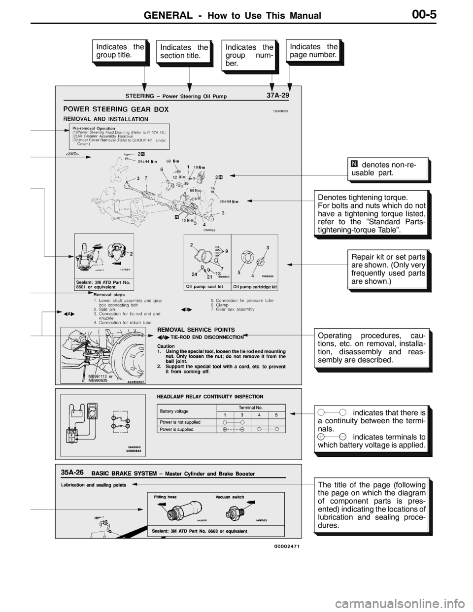
Denotes tightening torque.
For bolts and nuts which do not
have a tightening torque listed,
refer to the “Standard Parts-
tightening-torque Table”.
indicates that there is
a continuity between the termi-
nals.
indicates terminals to
which battery voltage is applied.
Indicates the
section title.Indicates the
group num-
ber.Indicates the
page number.Indicates the
group title.
denotes non-re-
usable part.
Repair kit or set parts
are shown. (Only very
frequently used parts
are shown.)
Operating procedures, cau-
tions, etc. on removal, installa-
tion, disassembly and reas-
sembly are described.
The title of the page (following
the page on which the diagram
of component parts is pres-
ented) indicating the locations of
lubrication and sealing proce-
dures.
Page 406 of 1449

GENERAL -Standard Part/Tightening-Torque Table00-28
STANDARD PART/TIGHTENING-TORQUE TABLE
Each torque value in the table is a standard value
for tightening under the following conditions.
(1) Bolts, nuts and washers are all made of steel
and plated with zinc.
(2) The threads and bearing surface of bolts and
nuts are all in dry condition.The values in the table are not applicable:
(1) If toothed washers are inserted.
(2) If plastic parts are fastened.
(3) If bolts are tightened to plastic or die-cast
inserted nuts.
(4) If self-tapping screws or self-locking nuts are
used.
Standard bolt and nut tightening torque
Thread sizeTorque N·m
Bolt nominal
diameter (mm)Pitch (mm)Head mark “4”Head mark “7”Head mark “8”
M50.82.50.55.01.06.01.0
M61.05.01.09.02.0102
M81.25122224254
M101.252444410537
M121.2541883129812
M141.573121402015525
M161.511 0202103023535
M181.5165253004034050
M201.5225354106048070
M221.5300405558564595
M241.539555735105855125
Flange bolt and nut tightening torque
Thread sizeTorque N·m
Bolt nominal
diameter (mm)Pitch (mm)Head mark “4”Head mark “7”Head mark “8”
M61.05.01.0102122
M81.25132244275
M101.25264499587
M101.52444585510
M121.25468951510515
M121.7543883129812
NOTE
1. Be sure to use only the specified bolts and nuts, and always tighten them to the specified torques.
2. Bolts marked with indications such as 4T or 7T are reinforced bolts. The larger the number, the
greater the bolt strength.
Page 427 of 1449

ENGINE -Camshaft and Camshaft Oil Seal11A-21
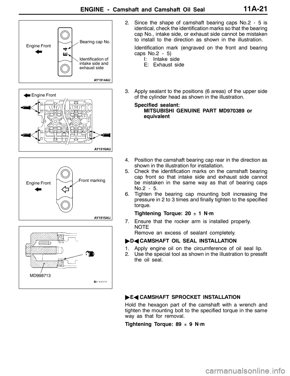
2. Since the shape of camshaft bearing caps No.2 - 5 is
identical, check the identification marks so that the bearing
cap No., intake side, or exhaust side cannot be mistaken
to install to the direction as shown in the illustration.
Identification mark (engraved on the front and bearing
caps No.2 - 5)
I: Intake side
E: Exhaust side
3. Apply sealant to the positions (6 areas) of the upper side
of the cylinder head as shown in the illustration.
Specified sealant:
MITSUBISHI GENUINE PART MD970389 or
equivalent
4. Position the camshaft bearing cap rear in the direction as
shown in the illustration for installation.
5. Check the identification marks on the camshaft bearing
cap front so that intake side and exhaust side cannot
be mistaken in the same way as that of bearing caps
No.2 - 5.
6. Tighten the bearing cap mounting bolt increasing the
pressure in 2 to 3 times and finally tighten to the specified
torque.
Tightening Torque: 20±1 N·m
7. Ensure that the rocker arm is installed properly.
NOTE
Remove an excess of sealant completely.
"DACAMSHAFT OIL SEAL INSTALLATION
1. Apply engine oil on the circumference of oil seal lip.
2. Use the special tool as shown in the illustration to pressfit
the oil seal.
"EACAMSHAFT SPROCKET INSTALLATION
Hold the hexagon part of the camshaft with a wrench and
tighten the mounting bolt to the specified torque in the same
way as that for removal.
Tightening Torque: 89±9 N·m
Engine FrontBearing cap No.
Identification of
intake side and
exhaust side
Engine Front
Front markingEngine Front
MD998713
Page 428 of 1449

ENGINE -Camshaft and Camshaft Oil Seal11A-22
"FACAMSHAFT POSITION SENSOR SUPPORT
INSTALLATION
1. Remove sealant remained on the camshaft position
sensor support.
2. Apply sealant to the flange of the camshaft position sensor
support and install to the cylinder head.
Specified sealant:
MITSUBISHI GENUINE PART MD970389 or
equivalent
3. Tighten the camshaft position sensor support mounting
bolt to the specified torque.
Tightening Torque: 14±1 N·m
"GACAMSHAFT POSITION SENSING CYLINDER
INSTALLATION
1. Set the dowel pin of the exhaust camshaft to the position
(No.1cylinder at compression TDC) as shown in the
illustration.
NOTE
Use the force of the exhaust valve spring to rotate
counterclockwise.
2. Install the vane (small) of the camshaft position sensing
cylinder at an angle of approximately 45 degrees to the
position of the dowel pin of the exhaust camshaft.
3. Tighten the camshaft position sensing cylinder mounting
bolt to the specified torque.
Tightening Torque: 22±4 N·m
"HARADIATOR UPPER HOSE CONNECTION
1. Insert the radiator upper hose to the convex part of the
water outlet fitting.
2. Make the mating marks on the upper hose and the hose
clamp for installation.
"IAROCKER COVER GASKET INSTALLATION
1. Remove sealant remained on the rocker cover.
2. Apply sealant to the positions (4 areas) of the lower side of
the rocker cover as shown in the illustration.
Specified sealant:
MITSUBISHI GENUINE PART MD970389 or
equivalent
3. Install the rocker cover gasket to the rocker cover.
ø3 mm
Dowel Pin
Vane (small)
Approximately 45_
Vane (large)
Page 431 of 1449

ENGINE -Oil Pan11A-25
INSTALLATION SERVICE POINTS
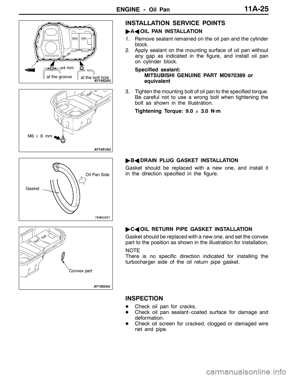
"AAOIL PAN INSTALLATION
1. Remove sealant remained on the oil pan and the cylinder
block.
2. Apply sealant on the mounting surface of oil pan without
any gap as indicated in the figure, and install oil pan
on cylinder block.
Specified sealant:
MITSUBISHI GENUINE PART MD970389 or
equivalent
3. Tighten the mounting bolt of oil pan to the specified torque.
Be careful not to use a wrong bolt when tightening the
bolt as shown in the illustration.
Tightening Torque: 9.0±3.0 N·m
"BADRAIN PLUG GASKET INSTALLATION
Gasket should be replaced with a new one, and install it
in the direction specified in the figure.
"CAOIL RETURN PIPE GASKET INSTALLATION
Gasket should be replaced with a new one, and set the convex
part to the position as shown in the illustration for installation.
NOTE
There is no specific direction indicated for installing the
turbocharger side of the oil return pipe gasket.
INSPECTION
DCheck oil pan for cracks.
DCheck oil pan sealant - coated surface for damage and
deformation.
DCheck oil screen for cracked, clogged or damaged wire
net and pipe.
ø4 mm
at the groove
at the bolt hole
M6×8mm
Gasket
Oil Pan Side
Convex part
Page 433 of 1449

ENGINE -Crankshaft Oil Seal11A-27
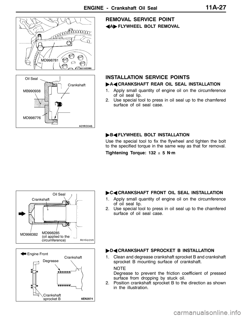
REMOVAL SERVICE POINT
AA"FLYWHEEL BOLT REMOVAL
INSTALLATION SERVICE POINTS
"AACRANKSHAFT REAR OIL SEAL INSTALLATION
1. Apply small quantity of engine oil on the circumference
of oil seal lip.
2. Use special tool to press in oil seal up to the chamfered
surface of oil seal case.
"BAFLYWHEEL BOLT INSTALLATION
Use the special tool to fix the flywheel and tighten the bolt
to the specified torque in the same way as that for removal.
Tightening Torque: 132±5 N·m
"CACRANKSHAFT FRONT OIL SEAL INSTALLATION
1. Apply small quantity of engine oil on the circumference
of oil seal lip.
2. Use special tool to press in oil seal up to the chamfered
surface of oil seal case.
"DACRANKSHAFT SPROCKET B INSTALLATION
1. Clean and degrease crankshaft sprocket B and crankshaft
sprocket B mounting surface of crankshaft.
NOTE
Degrease to prevent the friction coefficient of pressed
surface from dropping by stuck oil.
2. Position crankshaft sprocket B to the direction as shown
in the illustration.
MD998781
Crankshaft
Oil Seal
MB990938
MD998776
MD998382
Oil Seal
Crankshaft
MD998285
(oil applied to the
circumference)
Crankshaft
sprocket B
Degrease
Engine FrontCrankshaft