2007 MITSUBISHI LANCER EVOLUTION fuses
[x] Cancel search: fusesPage 88 of 1449

HOW TO READ THE WIRING DIAGRAMS -Composition and Contents of Wiring DiagramsA-2
COMPOSITION AND CONTENTS OF WIRING DIAGRAMS
(1) This manual consists of wiring harness diagrams, installation locations of individual parts, circuits
diagrams and index.
(2) In each section, all specifications are listed, including optional specifications. Accordingly, some
specifications may not be applicable for individual vehicles.
SectionBasic contents
Wiring harness
configuration
diagramsConnector locations and harness wiring configurations on actual vehicles are illustrated.
Single part
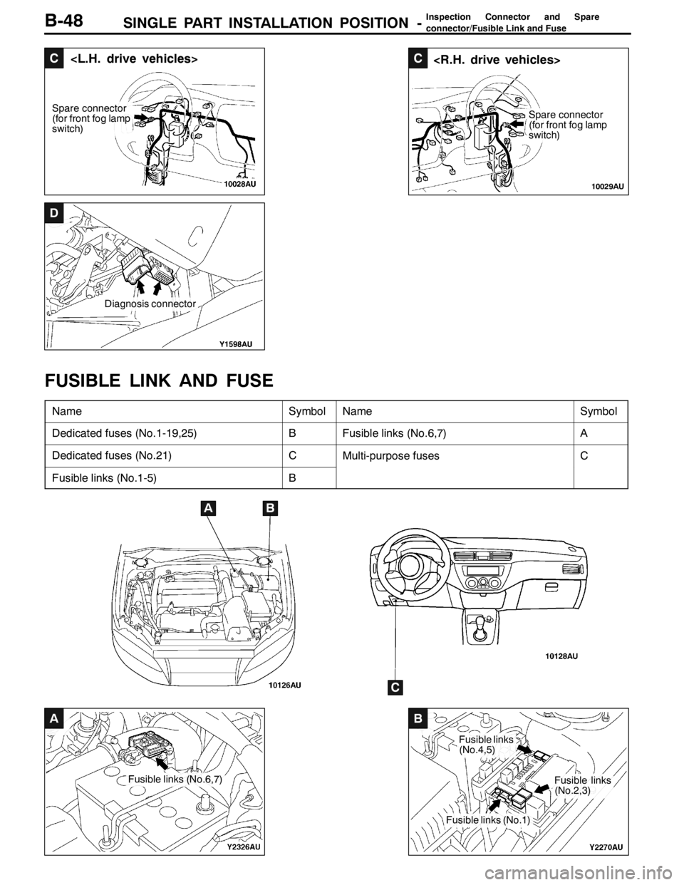
installation positionLocations are shown for each point of relays, electronic control units, sensors, solenoids,
solenoid valves, diodes, inspection connectors, spare connectors, fusible links, fuses, etc. In the
part’s lists, parts are listed in alphabetical order.
Circuit diagramsCircuits from power supply to earth are shown completely, classified according to system. There
is a main division into power circuits, and circuits classified by system. The circuits classified by
system also include operation and troubleshooting hints.
DJunction block
The entire circuit for the junction block is described, because only the part of the junction
block needed is normally shown in each circuit diagram.
DJoint connectors
The internal circuits for all joint connectors are described, because only the part needed
is shown in each circuit diagram.
DPower supply circuits
Circuits from the battery to fusible link, dedicated fuses, ignition switch, general purpose
fuses, etc.
DCircuits classified by system
For each system, the circuits are shown from fuse to earth, excluding the power supply
sections.
DOperation
The standard operation of each system is briefly described, following the route of current
flow.
DTroubleshooting hints
This is a brief explanation of the inspection points that serve as hints when troubleshooting.
Explanations of the circuits controlled by the electronic control unit are omitted. Refer
to the related publications as required.
IndexAll components used are listed by connector number and component name.
Page 146 of 1449

SINGLE PART INSTALLATION POSITION -Inspection Connector and Spare
connector/Fusible Link and Fuse
C
Spare connector
(for front fog lamp
switch)
C
Spare connector
(for front fog lamp
switch)
10029AU
D
Diagnosis connector
A
Fusible links (No.6,7)
B
Fusible links
(No.4,5)
Fusible links (No.1)
Fusible links
(No.2,3)
B-48
FUSIBLE LINK AND FUSE
NameSymbolNameSymbol
Dedicated fuses (No.1-19,25)BFusible links (No.6,7)A
Dedicated fuses (No.21)CMulti-purpose fusesC
Fusible links (No.1-5)B
AB
C
Page 147 of 1449

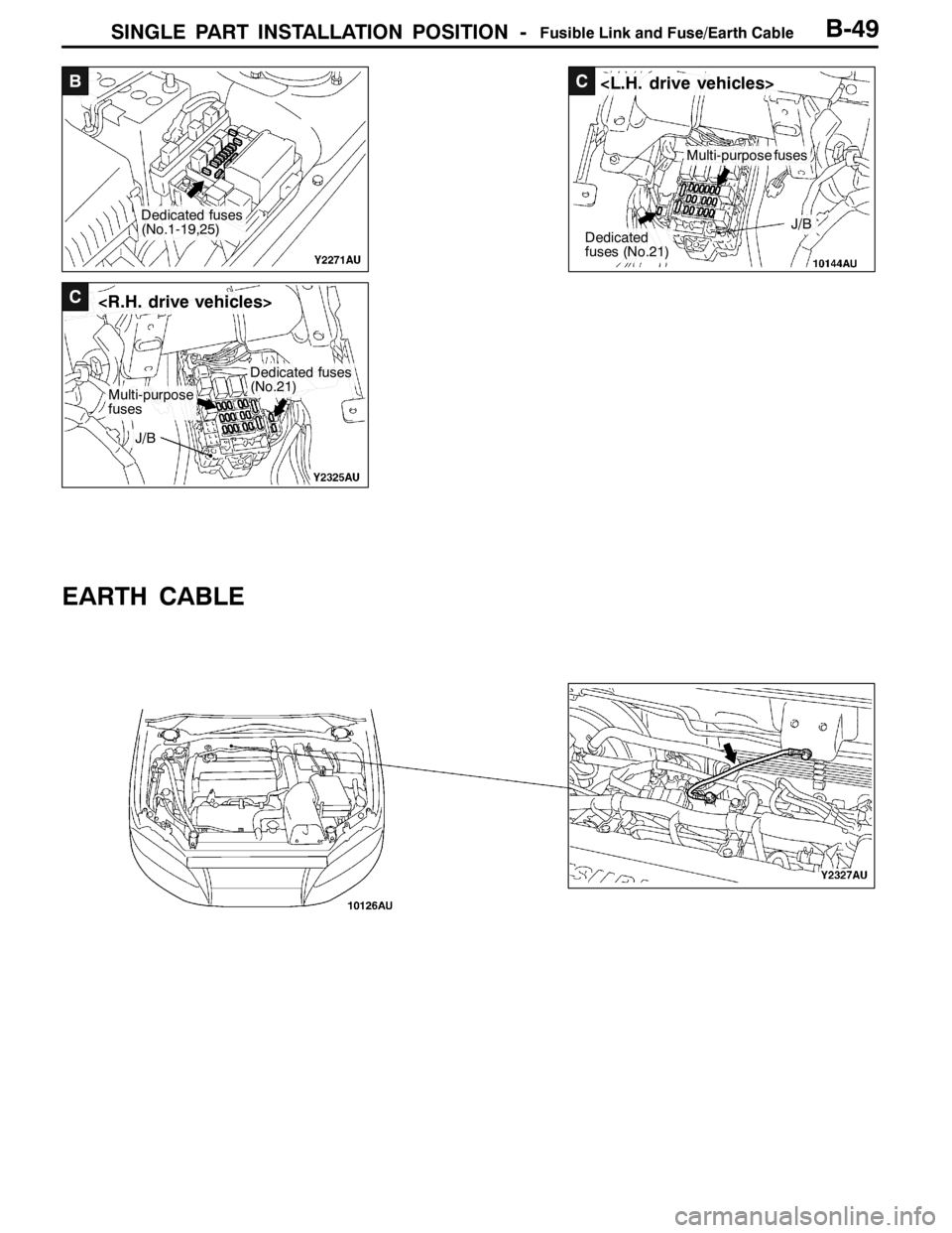
SINGLE PART INSTALLATION POSITION -Fusible Link and Fuse/Earth Cable
B
Dedicated fuses
(No.1-19,25)
C
Dedicated
fuses (No.21)
Multi-purpose fuses
J/B
C
Multi-purpose
fuses
Dedicated fuses
(No.21)
J/B
B-49
EARTH CABLE
Page 166 of 1449

CIRCUIT DIAGRAMSB-68
CENTRALIZED JUNCTION
FUSIBLE LINK
No.CircuitTypeHousing colourRated capacity
(A)
1Multi-purpoes fuses No. 15, 16, 17, 19, 20Screwed typeYellow60
2Cooling circuit and manual air conditioner circuitConnector typeRed50
3ABS circuitConnector typeYellow60
4Ignition switchConnector typeGreen40
5Power window circuitConnector typePink30
6Battery, fusible links No. 1, 2, 3, 4 and 5,
dedicated fuses No. 1, 2, 3, 4, 5, 6, 7, 8, 9, 10,
18, starting system, front-ECUScrewed type-100
7ACDScrewed type-60
(Relay box in engine compartment)
Front of vehicle
(Connected directly to battery positive (+) terminal)
Front of vehicle
1
234
5
6 7
6
Page 388 of 1449

GENERAL -How to Use Troubleshooting/Inspection Service Points00-10
HOW TO USE THE INSPECTION PROCEDURES
The causes of a high frequency of problems occurring in electronic circuitry are generally the connectors,
components, the ECU and the harnesses between connectors, in that order. These inspection procedures
follow this order, and they first try to discover a problem with a connector or a defective component.
DIndicator does not turn on or off even if control
mode switch is pressed.
DIndicator switch should not be illuminated is
illuminated.Probable cause
OK
OK
OK
Measure at switch connector A-44
DDisconnect the connector, and measure at the harness
side.
DVoltage between terminal 6 - earth and terminal 8 -
earth
OK:Approx. 5V
OK
NG
Check the following connector.A-44
Repair
OK
Check trouble symptom.
Replace the ECS-ECU.
In the above cases, the ECS switch circuit is defective or the indicator
circuit is defective.
CHECKING PROCEDURE 4
2. Indicates inspection carried out using the
MUT-II.
Indicates the operation and inspection proce-
dures.
Indicates the OK judgement conditions.
3. Detailed inspection procedures (methods)
such as component inspection and circuit
inspection are listed on a separate page, and
are given here for reference.
5. Inspect the contact condition at each connector terminal.
(Refer to Connector Inspection Service Points.)
The connector position can be located in the wiring diagram in the
electrical wiring manual by means of this symbol.
Caution
After carrying out connector inspection, always be sure to
reconnect the connector as it was before.
6. Confirm that there are trouble symptoms. If trouble symptoms have
disappeared, the connector may have been inserted incorrectly and the
trouble symptom may have disappeared during inspection.
If it seems that trouble symptoms still remain, proceed to the next page of
instructions.
7. If trouble symptoms still remain up to this stage, there is a possibility that there is an
open or short circuit in the harness between the connectors, so check the harness.
Alternatively, the cause may be a defective ECU, so try replacing the ECU and check
if the trouble symptom disappears.
NGECU switch component inspection (Refer to P.33-44.)
NG
1. Comments on the diagnosis code or trouble
symptom above.
MUT-IIData list
17 Control mode selection switch
OK:Voltage changes between approx. 0V→approx.
2.5V→approx. 5V when the switch is operated.
4. Indicates voltage and resistance to be measured at a particular
connector.
(Refer to Connector Measurement Service Points.)
The connector position can be located in the wiring diagram in the
electrical wiring manual by means of this symbol.
Indicates operation and inspection procedures, inspection terminals
and inspection conditions.
Indicates the OK judgement conditions.
HARNESS INSPECTION
Check for an open or short circuit in the harness between the terminals which were defective according
to the connector measurements. Carry out this inspection while referring to the electrical wiring manual.
Here, “Check harness between power supply and terminal xx” also includes checking for blown fuses.
For inspection service points when there is a blown fuse, refer to “Inspection Service Points for a Blown
Fuse.”
MEASURES TO TAKE AFTER REPLACING THE ECU
If the trouble symptoms have not disappeared even after replacing the ECU, repeat the inspection procedure
from the beginning.
Page 1366 of 1449

SWS -Special Tools/Troubleshooting54B-2
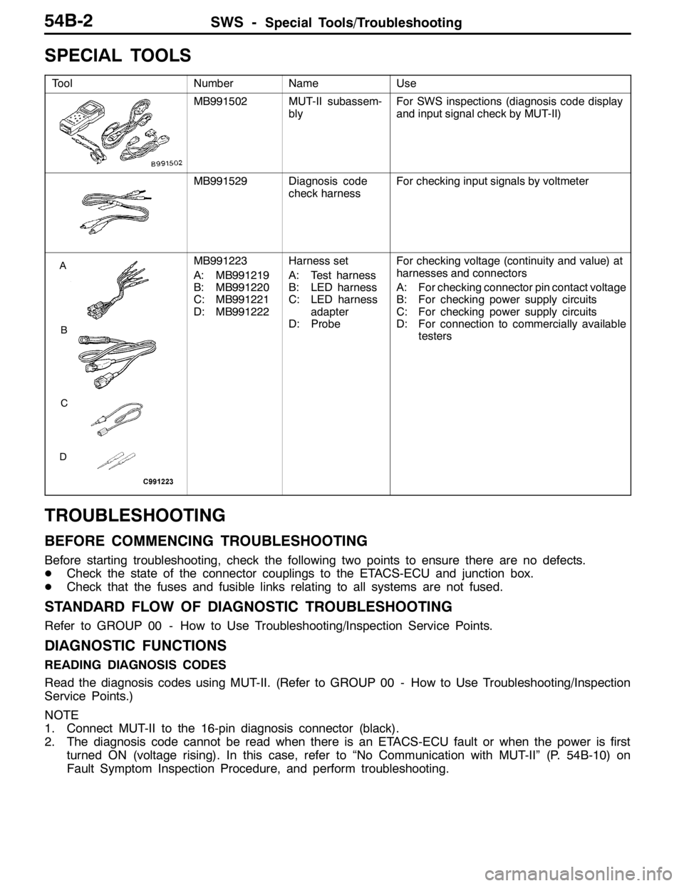
SPECIAL TOOLS
ToolNumberNameUse
MB991502MUT-II subassem-
blyFor SWS inspections (diagnosis code display
and input signal check by MUT-II)
MB991529Diagnosis code
check harnessFor checking input signals by voltmeter
A
B
C
D
MB991223
A: MB991219
B: MB991220
C: MB991221
D: MB991222Harness set
A: Test harness
B: LED harness
C: LED harness
adapter
D: ProbeFor checking voltage (continuity and value) at
harnesses and connectors
A: For checking connector pin contact voltage
B: For checking power supply circuits
C: For checking power supply circuits
D: For connection to commercially available
testers
TROUBLESHOOTING
BEFORE COMMENCING TROUBLESHOOTING
Before starting troubleshooting, check the following two points to ensure there are no defects.
DCheck the state of the connector couplings to the ETACS-ECU and junction box.
DCheck that the fuses and fusible links relating to all systems are not fused.
STANDARD FLOW OF DIAGNOSTIC TROUBLESHOOTING
Refer to GROUP 00 - How to Use Troubleshooting/Inspection Service Points.
DIAGNOSTIC FUNCTIONS
READING DIAGNOSIS CODES
Read the diagnosis codes using MUT-II. (Refer to GROUP 00 - How to Use Troubleshooting/Inspection
Service Points.)
NOTE
1. Connect MUT-II to the 16-pin diagnosis connector (black).
2. The diagnosis code cannot be read when there is an ETACS-ECU fault or when the power is first
turned ON (voltage rising). In this case, refer to “No Communication with MUT-II” (P. 54B-10) on
Fault Symptom Inspection Procedure, and perform troubleshooting.