2007 MITSUBISHI LANCER EVOLUTION torque
[x] Cancel search: torquePage 528 of 1449
ENGINE LUBRICATION -On-vehicle Service12-4
ON-VEHICLE SERVICE
ENGINE OIL CHECK
1. Pull out the level gauge slowly and check that the oil
level is in the illustrated range.
2. Check that the oil is not excessively dirty, that there is
no coolant or petrol mixed in, and that it has sufficient
viscosity.
ENGINE OIL REPLACEMENT
1. Start the engine and allow it to warm up until the
temperature of the coolant reaches 80_Cto90_C.
2. Remove the engine oil filler cap.
3. Remove the drain plug to drain oil.
Caution
Use care as oil could be hot.
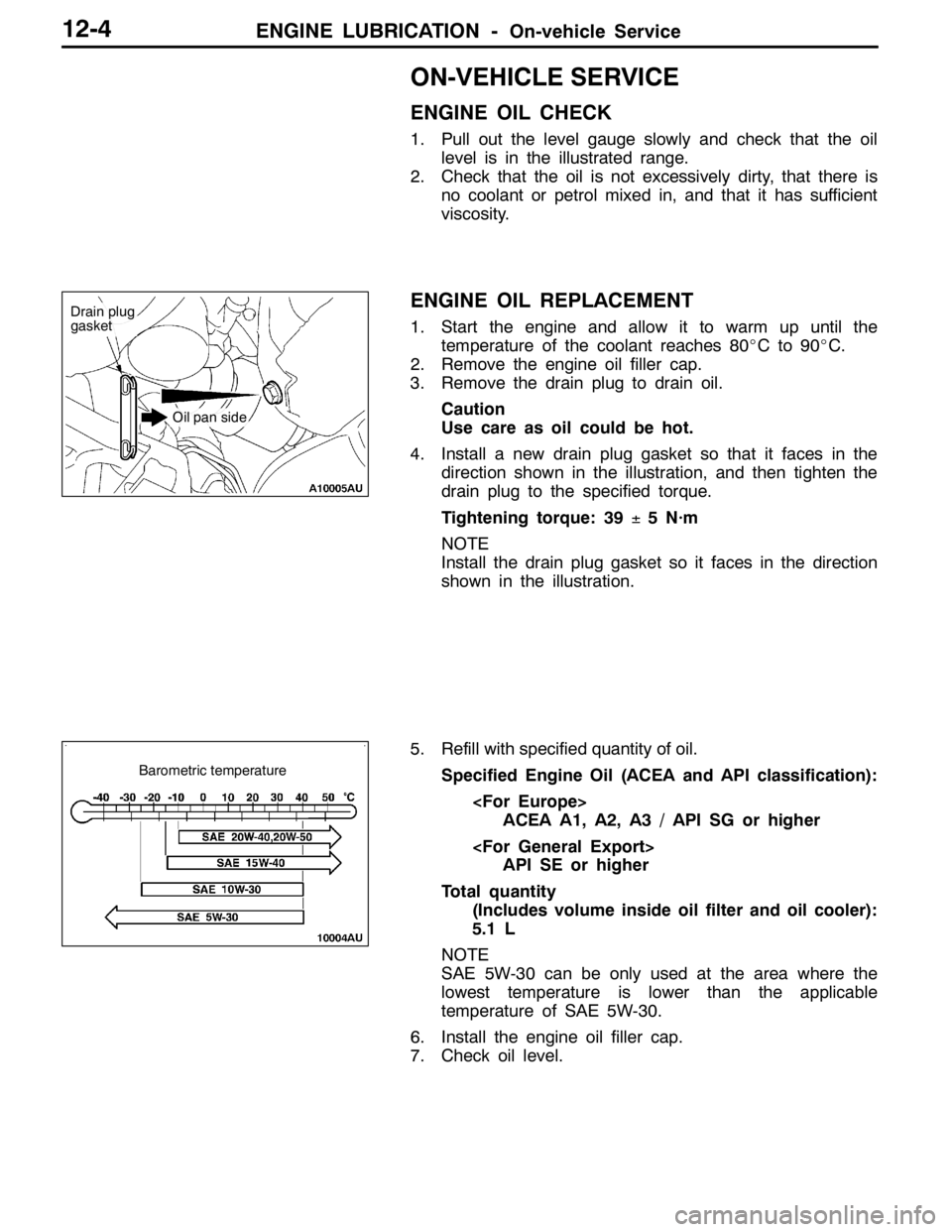
4. Install a new drain plug gasket so that it faces in the
direction shown in the illustration, and then tighten the
drain plug to the specified torque.
Tightening torque: 39±5 N·m
NOTE
Install the drain plug gasket so it faces in the direction
shown in the illustration.
5. Refill with specified quantity of oil.
Specified Engine Oil (ACEA and API classification):
ACEA A1, A2, A3 / API SG or higher
API SE or higher
Total quantity
(Includes volume inside oil filter and oil cooler):
5.1 L
NOTE
SAE 5W-30 can be only used at the area where the
lowest temperature is lower than the applicable
temperature of SAE 5W-30.
6. Install the engine oil filler cap.
7. Check oil level.
Drain plug
gasket
Oil pan side
Barometric temperature
Page 530 of 1449
ENGINE LUBRICATION -On-vehicle Service12-6
4. Install the oil pressure gauge.
NOTE
Use a adapter of PT 1/8 thread.
5. Run the engine to warm it.
6. After the engine has been warmed up, check that oil
pressure is within the standard value.
Standard value:
At idle: 29 kPa or more
At 3,500 r/min: 294 - 686 kPa
7. Remove the oil pressure gauge.
8. Apply the specified sealant to the thread of oil pressure
switch.
Specified sealant: 3M ATD Part No. 8660 or equivalent
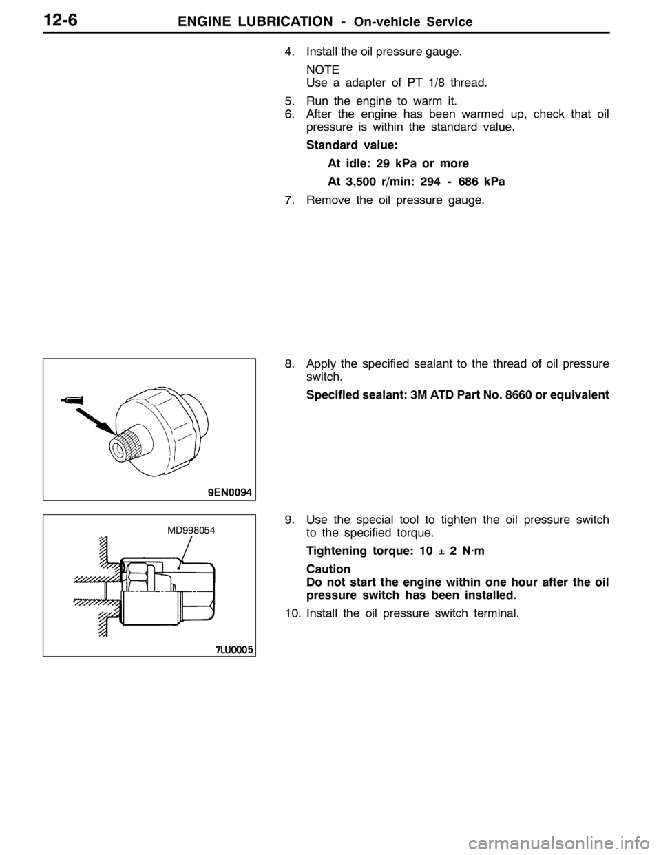
9. Use the special tool to tighten the oil pressure switch
to the specified torque.
Tightening torque: 10±2 N·m
Caution
Do not start the engine within one hour after the oil
pressure switch has been installed.
10. Install the oil pressure switch terminal.
MD998054
Page 662 of 1449

MPI -On-vehicle Service13A-130
14. If any of fuel pressure measured in steps 10 to 13 is out of
specification, troubleshoot and repair according to the
table below.
SymptomProbable causeRemedy
DFuel pressure too low
DFuelpressuredropsafterracing
Clogged fuel filterReplace fuel filter
DFuelpressuredrops after racing
DNo fuel pressure in fuel return
hose
Fuel leaking to return side due to poor
fuel regulator valve seating or settled
springReplace fuel pressure regulator
Low fuel pump delivery pressureReplace fuel pump
Fuel pressure too highBinding valve in fuel pressure
regulatorReplace fuel pressure regulator
Clogged fuel return hose or pipeClean or replace hose or pipe
Same fuel pressure when vacuum
hose is connected and when
disconnected
Damaged vacuum hose or clogged
nippleReplace vacuum hose or clean nipple
disconnectedFuel pressure control system
malfunctionCheck the fuel pressure control
system
15. Stop the engine and check change of fuel pressure gauge
reading. Normal if the reading does not drop within 2
minutes. If it does, observe the rate of drop and
troubleshoot and repair according to the table below.
SymptomProbable causeRemedy
Fuel pressure drops gradually after
engineisstopped
Leaky injectorReplace injector
engineisstopped
Leaky fuel regulator valve seatReplace fuel pressure regulator
Fuel pressure drops sharply
immediately after engine is stoppedCheck valve in fuel pump is held openReplace fuel pump
16. Release residual pressure from the fuel pipe line.
(Refer to P.13A-125.)
17. Remove the fuel pressure gauge and special tool from
the delivery pipe.
Caution
Cover the hose connection with rags to prevent splash
of fuel that could be caused by some residual pressure
in the fuel pipe line.
18. Replace the O-ring at the end of the fuel high pressure
hose with a new one. Furthermore, apply engine oil to
the new O-ring before replacement.
19. Fit the fuel high pressure hose over the delivery pipe
and tighten the bolt to specified torque.
Tightening torque: 5.0±1.0 N·m
20. Check for any fuel leaks by following the procedure in
step 7.
21. Disconnect the MUT-II.
Page 665 of 1449
MPI -On-vehicle Service13A-133
3. Measure resistance while heating the sensor using a hair
drier.
Normal condition:
Temperature (_C)Resistance (kΩ)
HigherSmaller
4. If the value deviates from the standard value or the
resistance remains unchanged, replace the air flow sensor
assembly.
ENGINE COOLANT TEMPERATURE SENSOR
CHECK
Caution
Be careful not to touch the connector (resin section) with
the tool when removing and installing.
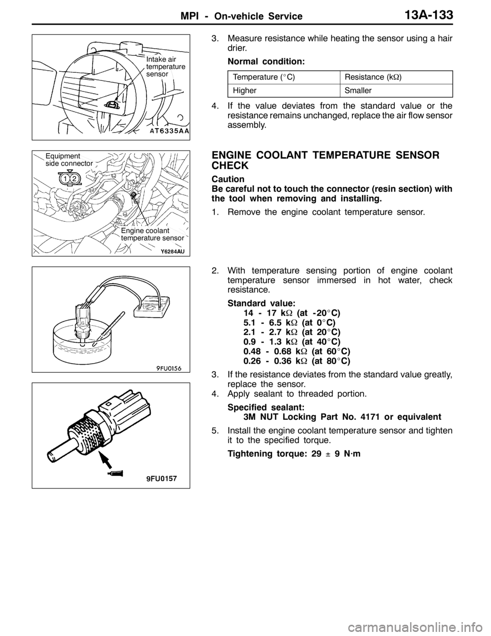
1. Remove the engine coolant temperature sensor.
2. With temperature sensing portion of engine coolant
temperature sensor immersed in hot water, check
resistance.
Standard value:
14 - 17 kΩ(at - 20_C)
5.1 - 6.5 kΩ(at 0_C)
2.1 - 2.7 kΩ(at 20_C)
0.9 - 1.3 kΩ(at 40_C)
0.48 - 0.68 kΩ(at 60_C)
0.26 - 0.36 kΩ(at 80_C)
3. If the resistance deviates from the standard value greatly,
replace the sensor.
4. Apply sealant to threaded portion.
Specified sealant:
3M NUT Locking Part No. 4171 or equivalent
5. Install the engine coolant temperature sensor and tighten
it to the specified torque.
Tightening torque: 29±9 N·m
Intake air
temperature
sensor
Engine coolant
temperature sensor
Equipment
side connector
12
Page 674 of 1449

MPI -Injector13A-142
REMOVAL SERVICE POINT
AA"DELIVERY PIPE/INJECTOR REMOVAL
Remove the delivery pipe (with the injectors attached to it).
Caution
Care must be taken, when removing the delivery pipe,
not to drop the injector.
INSTALLATION SERVICE POINT
"AAINJECTOR/FUEL PRESSURE REGULATOR
/HIGH-PRESSURE FUEL HOSE INSTALLATION
1. Apply a drop of new engine oil to the O-ring.
Caution
Be sure not to let engine oil enter the delivery pipe.
2. While turning the injector, high-pressure fuel hose and
fuel pressure regulator to the right and left, install the
delivery pipe, while being careful not to damage the O-ring.
After installing, check that the hose turns smoothly.
3. If it does not turn smoothly, the O-ring may be trapped,
remove the injector, high-pressure fuel hose or fuel
pressure regulator and then re-insert it into the delivery
pipe and check once again.
4. Tighten the high-pressure fuel hose and fuel pressure
regulator to the specified torque.
Tightening torque:
5.0±1.0 N·m (High-pressure fuel hose)
8.9±1.9 N·m (Fuel pressure regulator)
Page 682 of 1449
FUEL SUPPLY - General Information/On-vehicle Service13B-2
GENERAL INFORMATION
DThe steel fuel tank is located under the floor of the rear seats to provide increased safety and increase
the amount of luggage compartment space.
DThe fuel tank has been equipped with a valve assembly which incorporates a fuel cut-off valve to
prevent fuel from leaking out in the event of a collision for adjusting the pressure inside the fuel
tank.
DThe fuel pump module contains a fuel pump, fuel filter, and fuel pressure regulator.
ON-VEHICLE SERVICE
FUEL PUMP AND GAUGE ASSEMBLY (FUEL
PUMP)
1. FUEL PUMP OPERATION CHECK
Refer to GROUP 13A - On-vehicle service
2. FUEL PUMP REPLACEMENT
(1) Remove the rear seat cushion assembly.
(Refer to GROUP 52A.)
(2) Remove the service hole cover.
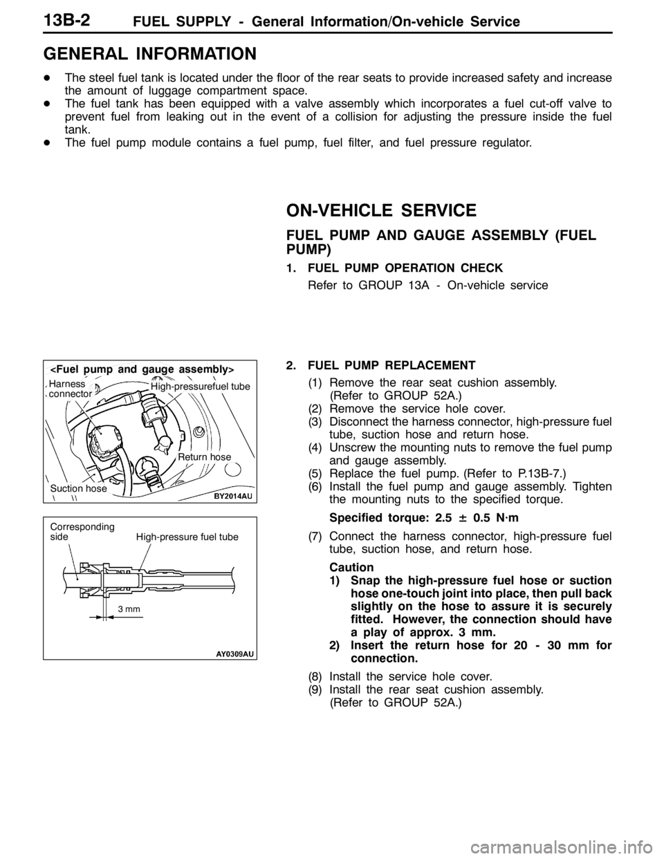
(3) Disconnect the harness connector, high-pressure fuel
tube, suction hose and return hose.
(4) Unscrew the mounting nuts to remove the fuel pump
and gauge assembly.
(5) Replace the fuel pump. (Refer to P.13B-7.)
(6) Install the fuel pump and gauge assembly. Tighten
the mounting nuts to the specified torque.
Specified torque: 2.5± 0.5 N·m
(7) Connect the harness connector, high-pressure fuel
tube, suction hose, and return hose.
Caution
1) Snap the high-pressure fuel hose or suction
hose one-touch joint into place, then pull back
slightly on the hose to assure it is securely
fitted. However, the connection should have
a play of approx. 3 mm.
2) Insert the return hose for 20 - 30 mm for
connection.
(8) Install the service hole cover.
(9) Install the rear seat cushion assembly.
(Refer to GROUP 52A.)
Harness
connectorHigh-pressurefuel tube
Suction hose
Return hose
3mm
Corresponding
sideHigh-pressure fuel tube
Page 683 of 1449
FUEL SUPPLY - On-vehicle Service/Fuel tank13B-3
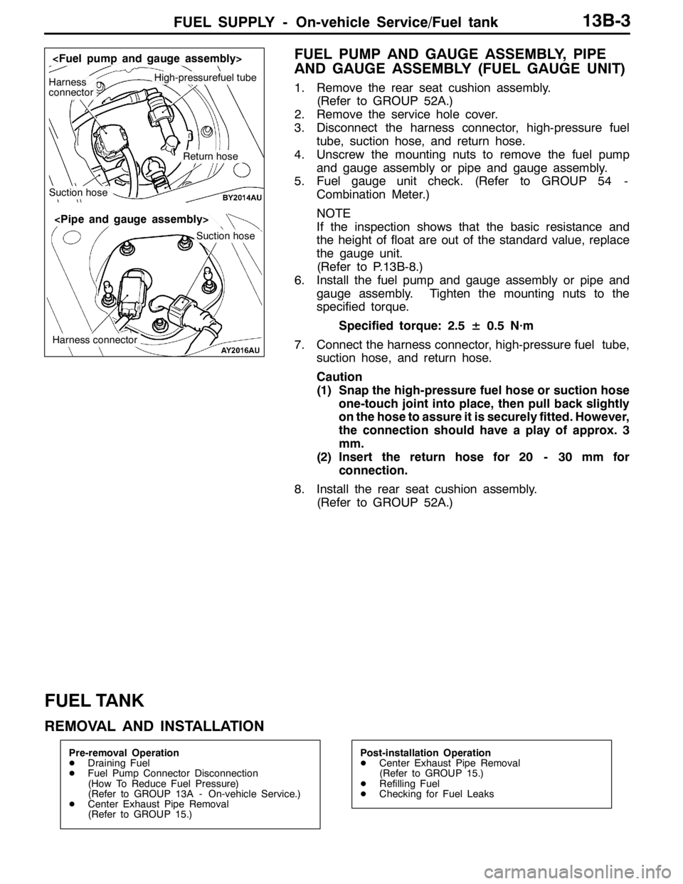
FUEL PUMP AND GAUGE ASSEMBLY, PIPE
AND GAUGE ASSEMBLY (FUEL GAUGE UNIT)
1. Remove the rear seat cushion assembly.
(Refer to GROUP 52A.)
2. Remove the service hole cover.
3. Disconnect the harness connector, high-pressure fuel
tube, suction hose, and return hose.
4. Unscrew the mounting nuts to remove the fuel pump
and gauge assembly or pipe and gauge assembly.
5. Fuel gauge unit check. (Refer to GROUP 54 -
Combination Meter.)
NOTE
If the inspection shows that the basic resistance and
the height of float are out of the standard value, replace
the gauge unit.
(Refer to P.13B-8.)
6. Install the fuel pump and gauge assembly or pipe and
gauge assembly. Tighten the mounting nuts to the
specified torque.
Specified torque: 2.5± 0.5 N·m
7. Connect the harness connector, high-pressure fuel tube,
suction hose, and return hose.
Caution
(1) Snap the high-pressure fuel hose or suction hose
one-touch joint into place, then pull back slightly
on the hose to assure it is securely fitted. However,
the connection should have a play of approx. 3
mm.
(2) Insert the return hose for 20 - 30 mm for
connection.
8. Install the rear seat cushion assembly.
(Refer to GROUP 52A.)
FUEL TANK
REMOVAL AND INSTALLATION
Pre-removal Operation
DDraining Fuel
DFuel Pump Connector Disconnection
(How To Reduce Fuel Pressure)
(Refer to GROUP 13A - On-vehicle Service.)
DCenter Exhaust Pipe Removal
(Refer to GROUP 15.)Post-installation Operation
DCenter Exhaust Pipe Removal
(Refer to GROUP 15.)
DRefilling Fuel
DChecking for Fuel Leaks
High-pressurefuel tubeHarness
connector
Suction hose
Return hose
Suction hose
Harness connector
Page 695 of 1449
ENGINE COOLING -On-vehicle ServiceENGINE COOLING -On-vehicle Service14-7
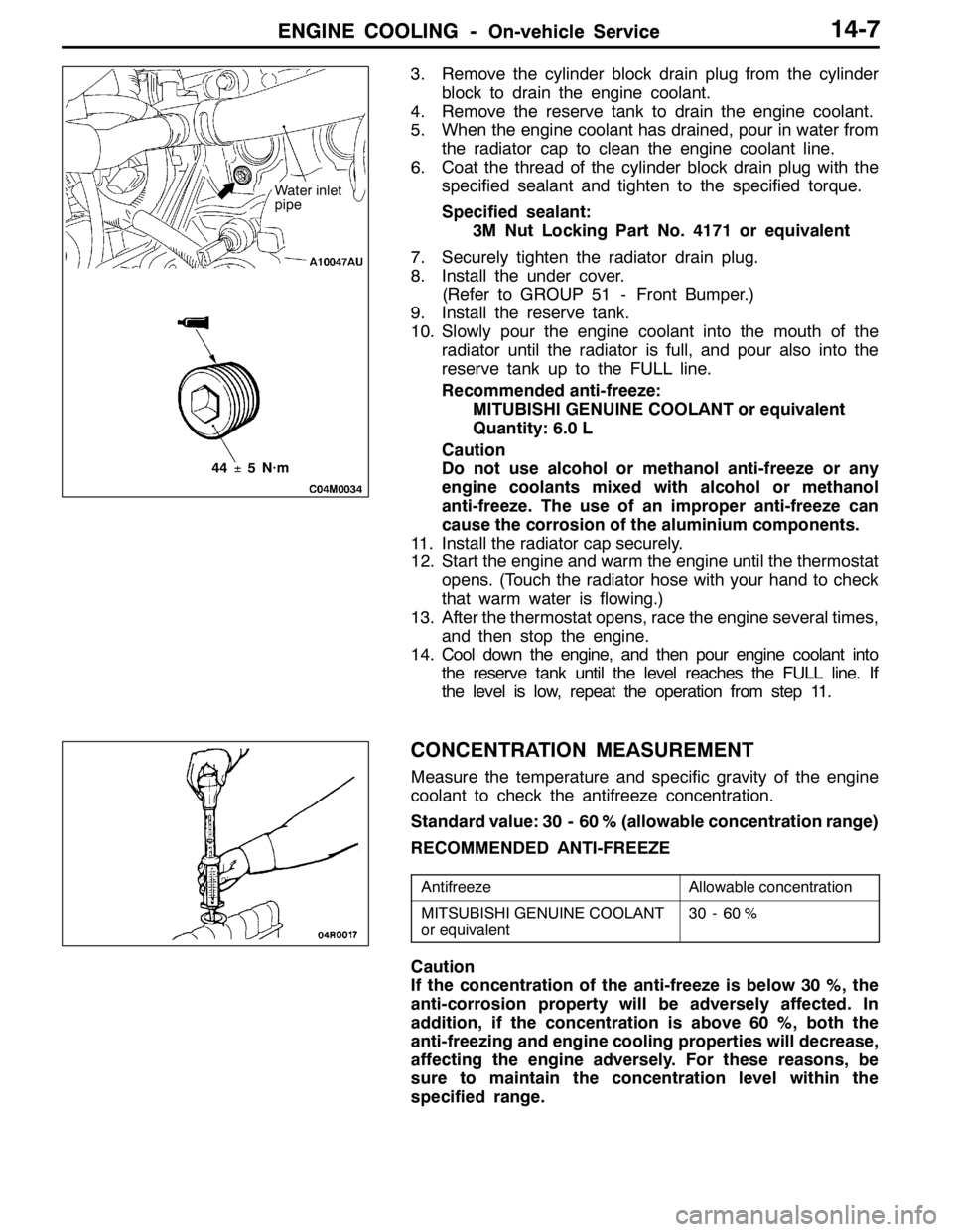
3. Remove the cylinder block drain plug from the cylinder
block to drain the engine coolant.
4. Remove the reserve tank to drain the engine coolant.
5. When the engine coolant has drained, pour in water from
the radiator cap to clean the engine coolant line.
6. Coat the thread of the cylinder block drain plug with the
specified sealant and tighten to the specified torque.
Specified sealant:
3M Nut Locking Part No. 4171 or equivalent
7. Securely tighten the radiator drain plug.
8. Install the under cover.
(Refer to GROUP 51 - Front Bumper.)
9. Install the reserve tank.
10. Slowly pour the engine coolant into the mouth of the
radiator until the radiator is full, and pour also into the
reserve tank up to the FULL line.
Recommended anti-freeze:
MITUBISHI GENUINE COOLANT or equivalent
Quantity: 6.0 L
Caution
Do not use alcohol or methanol anti-freeze or any
engine coolants mixed with alcohol or methanol
anti-freeze. The use of an improper anti-freeze can
cause the corrosion of the aluminium components.
11. Install the radiator cap securely.
12. Start the engine and warm the engine until the thermostat
opens. (Touch the radiator hose with your hand to check
that warm water is flowing.)
13. After the thermostat opens, race the engine several times,
and then stop the engine.
14. Cool down the engine, and then pour engine coolant into
the reserve tank until the level reaches the FULL line. If
the level is low, repeat the operation from step 11.
CONCENTRATION MEASUREMENT
Measure the temperature and specific gravity of the engine
coolant to check the antifreeze concentration.
Standard value: 30 - 60 % (allowable concentration range)
RECOMMENDED ANTI-FREEZE
AntifreezeAllowable concentration
MITSUBISHI GENUINE COOLANT
or equivalent30 - 60 %
Caution
If the concentration of the anti-freeze is below 30 %, the
anti-corrosion property will be adversely affected. In
addition, if the concentration is above 60 %, both the
anti-freezing and engine cooling properties will decrease,
affecting the engine adversely. For these reasons, be
sure to maintain the concentration level within the
specified range.
44±5N·m
Water inlet
pipe