Page 992 of 1449
REAR AXLE -Differential Carrier 27B-46
4. Clean the side bearing hub.
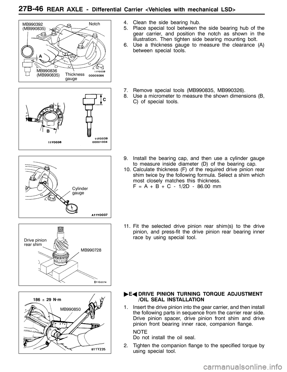
5. Place special tool between the side bearing hub of the
gear carrier, and position the notch as shown in the
illustration. Then tighten side bearing mounting bolt.
6. Use a thickness gauge to measure the clearance (A)
between special tools.
7. Remove special tools (MB990835, MB990326).
8. Use a micrometer to measure the shown dimensions (B,
C) of special tools.
9. Install the bearing cap, and then use a cylinder gauge
to measure inside diameter (D) of the bearing cap.
10. Calculate thickness (F) of the required drive pinion rear
shim twice by the following formula. Select a shim which
most closely matches this thickness.
F = A + B + C - 1/2D - 86.00 mm
11. Fit the selected drive pinion rear shim(s) to the drive
pinion, and press-fit the drive pinion rear bearing inner
race by using special tool.
"EADRIVE PINION TURNING TORQUE ADJUSTMENT
/OIL SEAL INSTALLATION
1. Insert the drive pinion into the gear carrier, and then install
the following parts in sequence from the carrier rear side.
Drive pinion spacer, drive pinion front shim and drive
pinion front bearing inner race, companion flange.
NOTE
Do not install the oil seal.
2. Tighten the companion flange to the specified torque by
using special tool.
Thickness
gauge
MB990392
(MB990835)Notch
MB990836
(MB990835)A
BC
Cylinder
gauge
Drive pinion
rear shim
MB990728
MB990850
186±29 N·m
Page 993 of 1449
REAR AXLE -Differential Carrier 27B-47
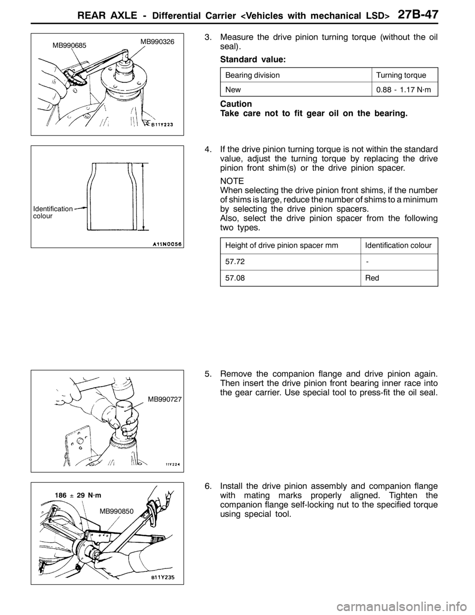
3. Measure the drive pinion turning torque (without the oil
seal).
Standard value:
Bearing divisionTurning torque
New0.88 - 1.17 N·m
Caution
Take care not to fit gear oil on the bearing.
4. If the drive pinion turning torque is not within the standard
value, adjust the turning torque by replacing the drive
pinion front shim(s) or the drive pinion spacer.
NOTE
When selecting the drive pinion front shims, if the number
of shims is large, reduce the number of shims to a minimum
by selecting the drive pinion spacers.
Also, select the drive pinion spacer from the following
two types.
Height of drive pinion spacer mmIdentification colour
57.72-
57.08Red
5. Remove the companion flange and drive pinion again.
Then insert the drive pinion front bearing inner race into
the gear carrier. Use special tool to press-fit the oil seal.
6. Install the drive pinion assembly and companion flange
with mating marks properly aligned. Tighten the
companion flange self-locking nut to the specified torque
using special tool.
MB990326
MB990685
Identification
colour
MB990727
MB990850
186±29 N·m
Page 994 of 1449
REAR AXLE -Differential Carrier 27B-48
7. Measure the drive pinion turning torque (with oil seal)
to verify that the drive pinion turning torque complies
with the standard value.
Standard value:
Bearing
divisionCompanion flange lubricationTurning torque
NewNone (With anti-rust agent)0.98 - 1.27 N·m
Gear oil applied0.49 - 0.58 N·m
8. If the turning torque is not within the standard value,
check the tightening torque of the companion flange
self-locking nut, and the installation of the oil seal.
"FADRIVE GEAR INSTALLATION
1. Clean the drive gear attaching bolts.
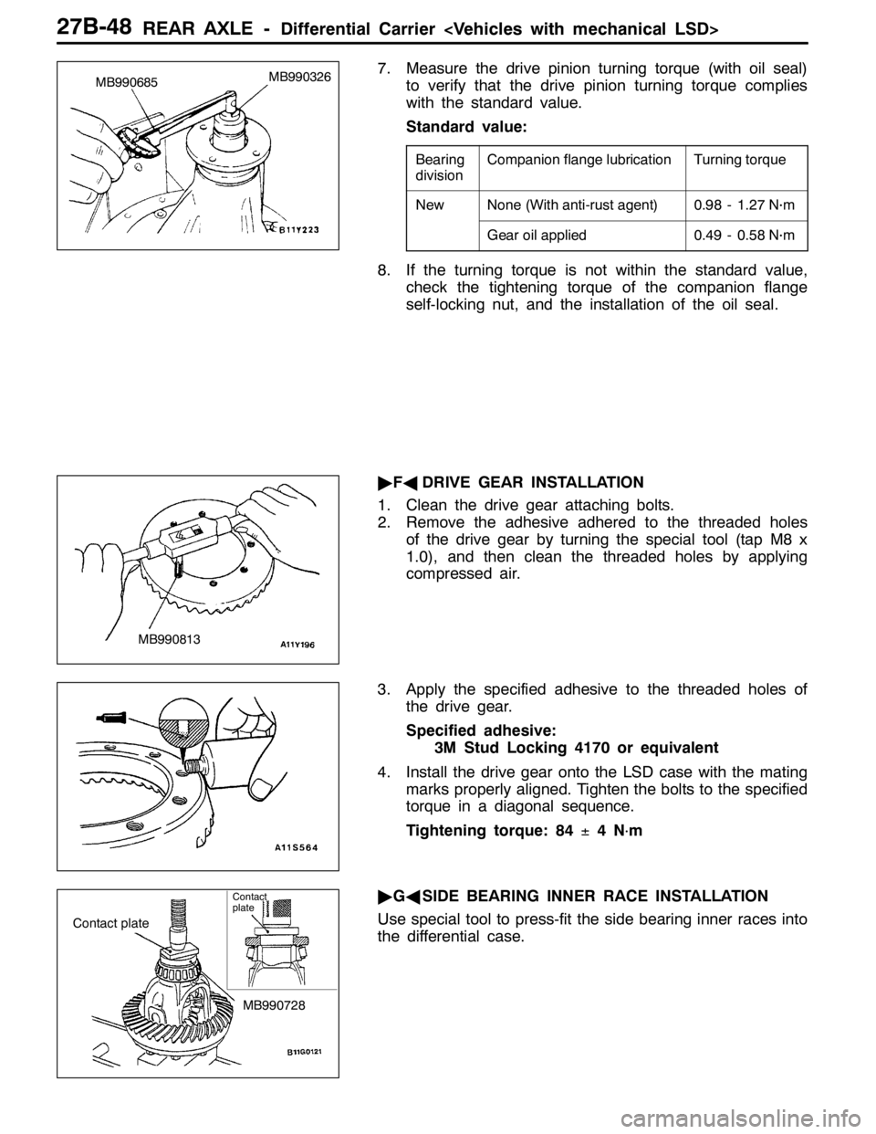
2. Remove the adhesive adhered to the threaded holes
of the drive gear by turning the special tool (tap M8 x
1.0), and then clean the threaded holes by applying
compressed air.
3. Apply the specified adhesive to the threaded holes of
the drive gear.
Specified adhesive:
3M Stud Locking 4170 or equivalent
4. Install the drive gear onto the LSD case with the mating
marks properly aligned. Tighten the bolts to the specified
torque in a diagonal sequence.
Tightening torque: 84±4N
·m
"GASIDE BEARING INNER RACE INSTALLATION
Use special tool to press-fit the side bearing inner races into
the differential case.
MB990326
MB990685
MB990813
Contact plate
MB990728
Contact
plate
Page 995 of 1449
REAR AXLE -Differential Carrier 27B-49
"HABEARING CAP INSTALLATION/FINAL DRIVE
GEAR BACKLASH ADJUSTMENT
Adjust drive gear backlash as follows:
1. Assemble the differential case with the side bearing outer
race to the gear carrier.
2. Press the differential case to one side to measure the
clearance of the side bearing outer race and the gear
carrier.
3. Select two pairs of the side bearing spacer with the thickness
derived from the sum of the clearance and a half of pre-load,
0.05 mm.
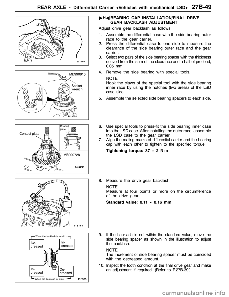
4. Remove the side bearing with special tools.
NOTE
Hook the claws of the special tool with the side bearing
inner race by using the notches (two areas) of the LSD
case side.
5. Assemble the selected side bearing spacers to each side.
6. Use special tools to press-fit the side bearing inner case
into the LSD case. After installing the outer race, assemble
the LSD case to the gear carrier.
7. Align the mating marks of differential carrier and the bearing
cap with each other to tighten to the specified torque.
Tightening torque: 37±2N
·m
8. Measure the drive gear backlash.
NOTE
Measure at four points or more on the circumference
of the drive gear.
Standard value: 0.11 - 0.16 mm
9. If the backlash is not within the standard value, move the
side bearing spacer as shown in the illustration to adjust
the backlash.
NOTE
The increment of side bearing spacer must be coincided
with the decreased amount.
10. Inspect the tooth condition at the final drive gear and make
an adjustment if required. (Refer to P.27B-39.)
MB990810
Socket
wrench
Contact plate
MB990728
Contact
plate
De-
creasedIn-
creased
De-
creased In-
creased
When the backlash is large
When the backlash is small
Page 996 of 1449
REAR AXLE -Differential Carrier 27B-50
11. Measure the drive gear runout.
Limit: 0.05 mm
12. When drive gear runout exceeds the limit, remove the
differential case and then the drive gears, moving them
to different positions and reinstall them.
13. If adjustment is not possible, replace the differential case
or drive gear and drive pinion as a set.
LSD CASE ASSEMBLY
DISASSEMBLY AND REASSEMBLY
19
2
6
20
5
11
3
4
12
15
16
13
14
10
1
1817
8
9
7
10
11
11
Differential gear set
1011
11
Disassembly steps
"CADLSD differential torque check
AA""BA1. Screw
2. Differential case A
3. Spring plate
4. Friction plate
5. Friction disc
6. Friction plate
7. Friction disc
8. Friction plate
9. Pressure ring10. Side gear
11. Pinion gear
12. Pinion shaft
13. Pressure ring
14. Friction plate
15. Friction disc
16. Friction plate
17. Friction disc
18. Friction plate
19. Friction plate
"AA20. Differential case B
Page 998 of 1449
REAR AXLE -Differential Carrier 27B-52
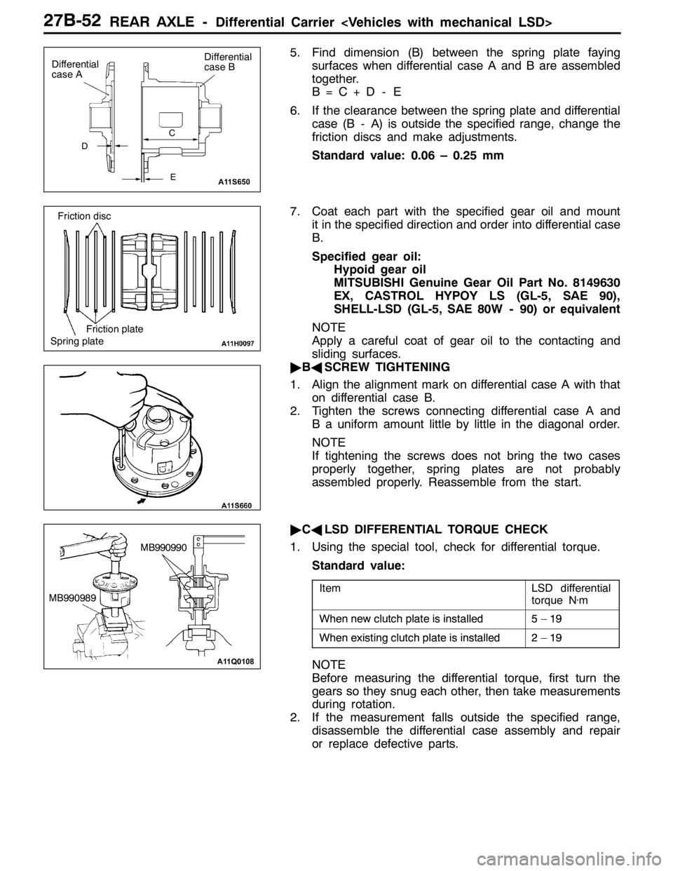
5. Find dimension (B) between the spring plate faying
surfaces when differential case A and B are assembled
together.
B=C+D - E
6. If the clearance between the spring plate and differential
case (B - A) is outside the specified range, change the
friction discs and make adjustments.
Standard value: 0.06 – 0.25 mm
7. Coat each part with the specified gear oil and mount
it in the specified direction and order into differential case
B.
Specified gear oil:
Hypoid gear oil
MITSUBISHI Genuine Gear Oil Part No. 8149630
EX, CASTROL HYPOY LS (GL-5, SAE 90),
SHELL-LSD (GL-5, SAE 80W - 90) or equivalent
NOTE
Apply a careful coat of gear oil to the contacting and
sliding surfaces.
"BASCREW TIGHTENING
1. Align the alignment mark on differential case A with that
on differential case B.
2. Tighten the screws connecting differential case A and
B a uniform amount little by little in the diagonal order.
NOTE
If tightening the screws does not bring the two cases
properly together, spring plates are not probably
assembled properly. Reassemble from the start.
"CALSD DIFFERENTIAL TORQUE CHECK
1. Using the special tool, check for differential torque.
Standard value:
ItemLSD differential
torque N·m
Whennewclutchplateisinstalled5–19When new clutchplateisinstalled5–19
Whenexistingclutchplateisinstalled2–19When existing clutchplateisinstalled2–19
NOTE
Before measuring the differential torque, first turn the
gears so they snug each other, then take measurements
during rotation.
2. If the measurement falls outside the specified range,
disassemble the differential case assembly and repair
or replace defective parts.
D
Differential
case A
E C
Differential
case B
Spring plateFriction plate Friction disc
MB990990
MB990989
Page 1004 of 1449
REAR AXLE -Differential Carrier 27B-58
TORQUE TRANSFER DIFFERENTIAL
DISASSEMBLY AND REASSEMBLY
Caution
1. The differential carrier assembly is non-maintainable.
2. No foreign matter should be allowed inside and at the joints of the differential carrier assembly.
14
2
6
4
35
7
1
9
10
8
3
4
11
13
12
186�¶29 N��m
32�¶2N��m 49�¶10 N��m
5�¶1N��m
9�¶1N��m 49�¶10 N��m
Disassembly steps
1. Drain plug
2. Packing
3. Filler plug
4. Gasket
5. Vent plug
6. Bleeder screw
7. CoverAA"8. Self-locking nut
9. Washer
10. Companion flange
11. Oil seal
"BA12. Oil seal
"AA13. Oil seal
14. Differential carrier assembly
Page 1014 of 1449
WHEEL AND TYRE -On-vehicle Service/Wheel and Tyre31-6
ON-VEHICLE SERVICE
TYRE INFLATION PRESSURE CHECK
NOTE
For information on tyre inflation pressure, refer to the label
attached near the driver’s side door striker.
TYRE WEAR CHECK
Measure the tread depth of tyres.
Limit: 1.6 mm
If the remaining tread depth is less than the limit, replace
the tyre.
NOTE
When the tread depth of tyres is reduced to 1.6 mm or less,
wear indicators will appear.
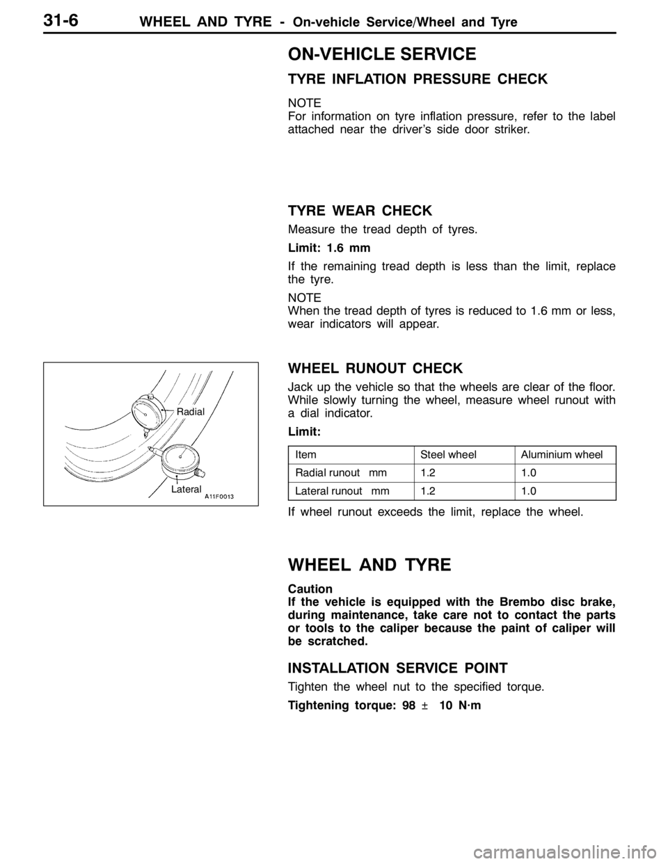
WHEEL RUNOUT CHECK
Jack up the vehicle so that the wheels are clear of the floor.
While slowly turning the wheel, measure wheel runout with
a dial indicator.
Limit:
ItemSteel wheelAluminium wheel
Radial runout mm1.21.0
Lateral runout mm1.21.0
If wheel runout exceeds the limit, replace the wheel.
WHEEL AND TYRE
Caution
If the vehicle is equipped with the Brembo disc brake,
during maintenance, take care not to contact the parts
or tools to the caliper because the paint of caliper will
be scratched.
INSTALLATION SERVICE POINT
Tighten the wheel nut to the specified torque.
Tightening torque: 98�¶10 N·m
Radial
Lateral