2007 MITSUBISHI LANCER EVOLUTION torque
[x] Cancel search: torquePage 1029 of 1449

FRONT SUSPENSION -Service Specifications/Special Tools33A-3
SERVICE SPECIFICATIONS
ItemsStandard value
Toe-inAt the centre of tyre tread mm0±2
Toe-angle (per wheel)0_00’±05’
Toe-out angle on turns (inner wheel when outer wheel at 20_)22_00’±1_30’
Steering angleInner wheel31_45’±1_30’
Outer wheel (for reference)27_15’
Camber (Selectable from 2 options)-1_00’±30’* or - 2_00’±30’*
Caster3_55’±30’*
Kingpin inclination13_45’±1_30’
Lower arm ball joint rotation starting torque N·m0.5 - 3.4
Lower arm pillow ball bushing rotation starting torque N·m0.5 - 3.0
NOTE
*: difference between right and left wheels: less than 30’
SPECIAL TOOLS
ToolsNumberNameUse
B
A
A: MB991237
B: MB991238A: Spring
compressor
body
B: Arm setCoil spring compression
BAMB991680
A: MB991681
B: MB991682Wrench set
A: Wrench
B: SocketStrut assembly disassembly and reassembly
MB991006Preload socketLower arm ball joint rotation starting torque
measurement
MB990326Preload socketLower arm pillow ball bushing rotation starting
torque measurement
Page 1030 of 1449

FRONT SUSPENSION -Special Tools/On-vehicle Service33A-4
Tools UseName Number
MB990800Ball joint remover &
installerLower arm ball joint dust cover press-in
MB990651BarLower arm pillow ball bushing removal and
press-fitting
MB990816Bushing remover &
installer base
MB991576Base
MB990635,
MB991113 or
MB991406Steering linkage
pullerTie rod end and knuckle disconnection
ON-VEHICLE SERVICE
WHEEL ALIGNMENT CHECK AND
ADJUSTMENT
Measure the wheel alignment with the vehicle parked on a
level surface.
The front suspension, steering system, and wheels should be
serviced to normal condition prior to measurement of wheel
alignment.
TOE-IN
Standard value:
At the centre of tyre tread 0±2mm
Toe angle (per wheel) 0_00’±05’
1. Adjust the toe-in by undoing the clip and lock nut, and
turning the left and right tie rod turnbuckles by the same
amount (in opposite directions).
NOTE
The toe will move out as the left turnbuckle is turned
toward the front of the vehicle and the right turnbuckle
is turned toward the rear of the vehicle.
2. Install the clip and tighten the lock nut to the specified torque.
Clip
Lock nut
Page 1031 of 1449
FRONT SUSPENSION -On-vehicle Service33A-5
Tightening torque: 52±2 N·m
3. Confirm that the toe-in is at the standard value.
4. Use a turning radius gauge to check that the steering
angle is at the standard value.
Standard value:
Inner wheels31_45’±1_30’
Outer wheels (for reference)27_15’
TOE-OUT ANGLE ON TURNS
To check the steering linkage, especially after the vehicle
has been involved in an accident or if an accident is presumed,
it is advisable to check the toe-out angle on turns in addition
to the wheel alignment.
Conduct this test on the left turn as well as on the right turn.
Standard value:
ItemsSpecifications
Toe-out angle on turns
(inner wheel when outer wheel at 20_)22_00’±1_30’
CAMBER, CASTER AND KINGPIN INCLINATION
Standard value:
ItemsSpecifications
Camber
(Selectable from 2 options)-1_00’±30’* or - 2_00’±30’*
Caster3_55’±30’*
Kingpin inclination13_45’±1_30’
NOTE
1. *: difference between right and left wheels must be less
than 30’
2. Caster and kingpin inclination are preset at the factory
and cannot be adjusted.
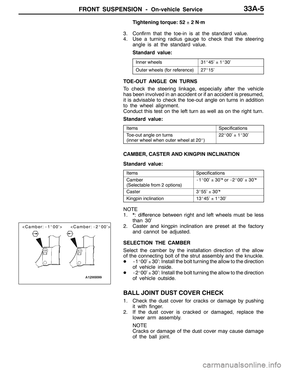
SELECTION THE CAMBER
Select the camber by the installation direction of the allow
of the connecting bolt of the strut assembly and the knuckle.
D-1
_00’±30’: Install the bolt turning the allow to the direction
of vehicle inside.
D-2
_00’±30’: Install the bolt turning the allow to the direction
of vehicle outside.
BALL JOINT DUST COVER CHECK
1. Check the dust cover for cracks or damage by pushing
it with finger.
2. If the dust cover is cracked or damaged, replace the
lower arm assembly.
NOTE
Cracks or damage of the dust cover may cause damage
of the ball joint.
Page 1033 of 1449
FRONT SUSPENSION -Strut Assembly33A-7
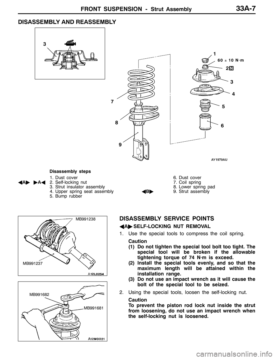
DISASSEMBLY AND REASSEMBLY
60±10 N·m
3
2
1
5
6
7
8
9
4
3
Disassembly steps
1. Dust cover
AA""AA2. Self-locking nut
3. Strut insulator assembly
4. Upper spring seat assembly
5. Bump rubber6. Dust cover
7. Coil spring
8. Lower spring pad
AB"9. Strut assembly
DISASSEMBLY SERVICE POINTS
AA"SELF-LOCKING NUT REMOVAL
1. Use the special tools to compress the coil spring.
Caution
(1) Do not tighten the special tool bolt too tight. The
special tool will be broken if the allowable
tightening torque of 74 N·m is exceed.
(2) Install the special tools evenly, and so that the
maximum length will be attained within the
installation range.
(3) Do not use an impact wrench as it will cause the
bolt of the special tool to be seized.
2. Using the special tools, loosen the self-locking nut.
Caution
To prevent the piston rod lock nut inside the strut
from loosening, do not use an impact wrench when
the self-locking nut is loosened.
MB991237
MB991238
MB991681
MB991682
Page 1034 of 1449
FRONT SUSPENSION -Strut Assembly33A-8
AB"STRUT ASSEMBLY REMOVAL
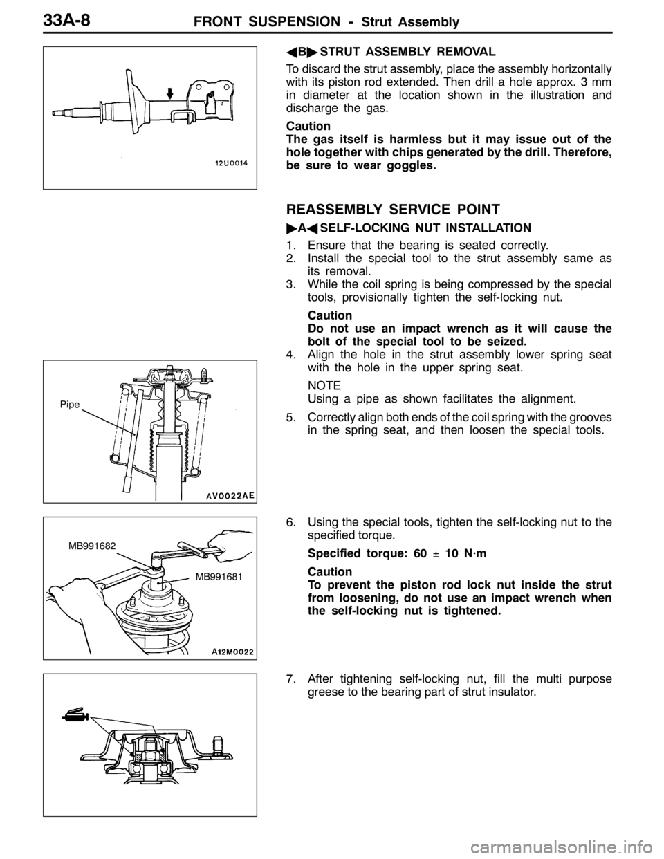
To discard the strut assembly, place the assembly horizontally
with its piston rod extended. Then drill a hole approx. 3 mm
in diameter at the location shown in the illustration and
discharge the gas.
Caution
The gas itself is harmless but it may issue out of the
hole together with chips generated by the drill. Therefore,
be sure to wear goggles.
REASSEMBLY SERVICE POINT
"AASELF-LOCKING NUT INSTALLATION
1. Ensure that the bearing is seated correctly.
2. Install the special tool to the strut assembly same as
its removal.
3. While the coil spring is being compressed by the special
tools, provisionally tighten the self-locking nut.
Caution
Do not use an impact wrench as it will cause the
bolt of the special tool to be seized.
4. Align the hole in the strut assembly lower spring seat
with the hole in the upper spring seat.
NOTE
Using a pipe as shown facilitates the alignment.
5. Correctly align both ends of the coil spring with the grooves
in the spring seat, and then loosen the special tools.
6. Using the special tools, tighten the self-locking nut to the
specified torque.
Specified torque: 60±10 N·m
Caution
To prevent the piston rod lock nut inside the strut
from loosening, do not use an impact wrench when
the self-locking nut is tightened.
7. After tightening self-locking nut, fill the multi purpose
greese to the bearing part of strut insulator.
Pipe
MB991681
MB991682
Page 1036 of 1449
FRONT SUSPENSION -Lower Arm Assembly33A-10
REMOVAL SERVICE POINT
AA"LOWER ARM AND CROSSMEMBER
DISCONNECTION
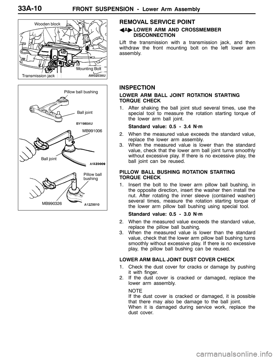
Lift the transmission with a transmission jack, and then
withdraw the front mounting bolt on the left lower arm
assembly.
INSPECTION
LOWER ARM BALL JOINT ROTATION STARTING
TORQUE CHECK
1. After shaking the ball joint stud several times, use the
special tool to measure the rotation starting torque of
the lower arm ball joint.
Standard value: 0.5 - 3.4 N·m
2. When the measured value exceeds the standard value,
replace the lower arm assembly.
3. When the measured value is lower than the standard
value, check that the lower arm ball joint turns smoothly
without excessive play. If there is no excessive play, the
ball joint can be reused.
PILLOW BALL BUSHING ROTATION STARTING
TORQUE CHECK
1. Insert the bolt to the lower arm pillow ball bushing, in
the opposite direction, insert the washer then install the
nut. After rotating the inner sleeve (contained washer)
several times, measure the rotation starting torque of
the lower arm pillow ball bushing using special tool.
Standard value: 0.5 - 3.0 N·m
2. When the measured value exceeds the standard value,
replace the pillow ball bushing.
3. When the measured value is lower than the standard
value, check that the lower arm pillow ball bushing turns
smoothly without excessive play. If there is no excessive
play, the pillow ball bushing can be reused.
LOWER ARM BALL JOINT DUST COVER CHECK
1. Check the dust cover for cracks or damage by pushing
it with finger.
2. If the dust cover is cracked or damaged, replace the
lower arm assembly.
NOTE
If the dust cover is cracked or damaged, it is possible
that there may also be damage to the ball joint.
When it is damaged during service work, replace the
dust cover.
Wooden block
Transmission jack
Mounting Bolt
Pillow ball
bushing
MB991006
Pillow ball bushing
Ball joint
Ball joint
MB990326
Page 1056 of 1449
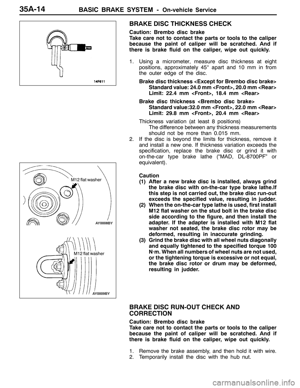
BASIC BRAKE SYSTEM -On-vehicle Service35A-14
BRAKE DISC THICKNESS CHECK
Caution: Brembo disc brake
Take care not to contact the parts or tools to the caliper
because the paint of caliper will be scratched. And if
there is brake fluid on the caliper, wipe out quickly.
1. Using a micrometer, measure disc thickness at eight
positions, approximately 45°apart and 10 mm in from
the outer edge of the disc.
Brake disc thickness
Standard value: 24.0 mm
Limit: 22.4 mm
Brake disc thickness
Standard value:32.0 mm
Limit: 29.8 mm
Thickness variation (at least 8 positions)
The difference between any thickness measurements
should not be more than 0.015 mm.
2. If the disc is beyond the limits for thickness, remove it
and install a new one. If thickness variation exceeds the
specification, replace the brake disc or grind it with
on-the-car type brake lathe (“MAD, DL-8700PF” or
equivalent).
Caution
(1) After a new brake disc is installed, always grind
the brake disc with on-the-car type brake lathe.If
this step is not carried out, the brake disc run-out
exceeds the specified value, resulting in judder.
(2) When the on-the-car type lathe is used, first install
M12 flat washer on the stud bolt in the brake disc
side according to the figure, and then install the
adapter. If the adapter is installed with M12 flat
washer not seated, the brake disc rotor may be
deformed, resulting in inaccurate grinding.
(3) Grind the brake disc with all wheel nuts diagonally
and equally tightened to the specified torque 100
N·m. When all numbers of wheel nuts are not used,
or the tightening torque is excessive or not equal,
the brake disc rotor or drum may be deformed,
resulting in judder.
BRAKE DISC RUN-OUT CHECK AND
CORRECTION
Caution: Brembo disc brake
Take care not to contact the parts or tools to the caliper
because the paint of caliper will be scratched. And if
there is brake fluid on the caliper, wipe out quickly.
1. Remove the brake assembly, and then hold it with wire.
2. Temporarily install the disc with the hub nut.
M12 flat washer
M12 flat washer
Page 1057 of 1449

BASIC BRAKE SYSTEM -On-vehicle Service35A-15
3. Place a dial gauge approximately 5 mm from the outer
circumference of the brake disc, and measure the run-out
of the disc.
Limit: 0.03 mm or less
4. If the brake disc run-out exceeds the limit, correct it as
follows:
(1) Chalk phase marks on the wheel stud and the brake
disc, which run-out is excessive.
(2) Remove the brake disc. Then place a dial gauge
as shown, and measure the wheel bearing axial play
by pushing and pulling the wheel hub.
Limit: 0.06 mm
(3) If the wheel bearing axial play exceeds the limit,
disassemble the hub and knuckle assembly to check
each part.
(4) If the wheel bearing axial play does not exceed the
limit, dephase the brake disc and secure it. Then
recheck the brake disc run-out.
5. If the run-out cannot be corrected by changing the phase
of the brake disc, replace the brake disc or grind it with
the on-the-car type brake lathe ( “MAD, DL-8700PF” or
equivalent).
Caution
(1) After a new brake disc is installed, always grind
the brake disc with on-the-car type brake lathe.
If this step is not carried out, the brake disc run-out
exceeds the specified value, resulting in judder.
(2) When the on-the-car type lathe is used, first install
M12 flat washer on the stud bolt in the brake disc
side according to the figure, and then install the
adapter. If the adapter is installed with M12 flat
washer not seated, the brake disc rotor may be
deformed, resulting in inaccurate grinding.
(3) Grind the brake disc with all wheel nuts diagonally
and equally tightened to the specified torque 100
N·m. When all numbers of wheel nuts are not used,
or the tightening torque is excessive or not equal,
the brake disc rotor or drum may be deformed,
resulting in judder.
M12 flat washer
M12 flat washer