2006 MERCEDES-BENZ SPRINTER diagram
[x] Cancel search: diagramPage 1572 of 2305
OPERATION
All of the circuits entering and leaving the fuse
block do so through the instrument panel wire har-
ness. Internal connection of all of the fuse block cir-
cuits is accomplished by an intricate combination of
hard wiring and bus bars. Internal relays and micro
processors allow the vehicle electronics to control
some of the power distribution circuits throughout
the vehicle. Refer to the Wiring section for complete
circuit diagrams.
REMOVAL
(1) Disconnect and isolate the negative battery
cable.
(2) Remove fuse block cover by rotating locking
screw 90É.
(3) Remove the steering column cover. Refer to the
Body section for the procedure.
(4) Unscrew fuse block connections and disconnect
all electrical connectors from the fuse block.
(5) Remove the fuse block from the steering col-
umn.
INSTALLATION
(1) Position the fuse block in the steering column.
(2) Install fuse block connections and connect all
electrical connectors on the fuse block.
(3) Install the steering column cover. Refer to the
Body section for the procedure.
(4) Install fuse block cover by rotating locking
screw 90É.
(5) Connect the negative battery cable.
(6) Set time and radio stations.
FUSE BLOCK #2
DESCRIPTION
An electrical fuse block is concealed under the
driver side front seat. The fuse block serves to dis-
tribute electrical current to many of the electrical
systems in the vehicle. The fuse block houses blade-
type mini fuses, blade-type automatic resetting cir-
cuit breakers and International Standards
Organization relays. Additional provisions are avail-
able in the fuse block for additional fuses and ISO
relays.
The molded plastic fuse block housing has an inte-
gral mounting bracket that is secured with screws to
the seat base. The driver side seat base also has a
snap-fit fuse access panel that can be removed for
service of the fuses and the relays. A finger recess is
molded into one end for easy removal. A fuse layout
map is molded onto the back side of the panel to
ensure proper fuse identification.
The fuse block is integral to the body wire harness.
If any internal circuit or the fuse block housing isfaulty or damaged, the entire fuse block and body
wire harness unit must be replaced.
OPERATION
All of the circuits entering and leaving the fuse
block do so through the body wire harness. Internal
connection of all of the fuse block circuits is accom-
plished by an intricate combination of hard wiring
and bus bars.
POWER DISTRIBUTION CEN-
TER
DESCRIPTION
All of the electrical current distributed throughout
this vehicle is directed through the Power Distribu-
tion Center (PDC). The molded plastic PDC housing
is located in the left front corner of the engine com-
partment, on the battery positive cable. The PDC
housing has a molded plastic cover that slides over
the PDC housing. The PDC cover is easily opened or
removed for service access.
The PDC unit cannot be repaired and is only ser-
viced as a unit with the headlamp and dash wire
harness. If the internal circuits or the PDC housing
are faulty or damaged, the headlamp and dash wire
harness unit must be replaced.
OPERATION
All of the current from the battery and the gener-
ator output enters the PDC through the positive bat-
tery cable. The PDC cover is removed to access the
battery and generator output connection B(+) termi-
nal studs. Internal connection of all of the PDC cir-
cuits is accomplished by an intricate combination of
hard wiring and bus bars. Refer to Wiring Diagrams
for the location of complete PDC circuit diagrams.
POWER OUTLET
DESCRIPTION
The power outlet is installed in the instrument
panel accessory switch plate, which is located near
the center of the instrument panel. The power outlet
base is secured by a snap fit within the instrument
panel. A plastic protective cap snaps over the power
outlet base when the power outlet is not being used.
While the power outlet is very similar to a cigar
lighter base unit, it does not include the two small
spring-clip retainers inside the bottom of the recepta-
cle shell that are used to secure the cigar lighter
heating element to the insulated contact.
The power outlet receptacle unit are available for
service. The power outlet receptacle cannot be
VA8W-97 POWER DISTRIBUTION 8W - 97 - 3
Page 1744 of 2305
TRANSMISSION
TABLE OF CONTENTS
page
AUTOMATIC TRANSMISSION NAG1 - SERVICE
INFORMATION............................1
AUTOMATIC TRANSMISSION NAG1 - SERVICE
INFORMATION
TABLE OF CONTENTS
page page
AUTOMATIC TRANSMISSION NAG1 - SERVICE
INFORMATION
DESCRIPTION..........................3
OPERATION............................4
DIAGNOSIS AND TESTING
AUTOMATIC TRANSMISSION............39
PRELIMINARY........................39
ROAD TESTING......................39
AUTOMATIC TRANSMISSION............40
STANDARD PROCEDURE - ALUMINUM
THREAD REPAIR......................42
REMOVAL.............................42
DISASSEMBLY.........................46
ASSEMBLY............................52
INSTALLATION.........................60
SCHEMATICS AND DIAGRAMS............65
SPECIFICATIONS - NAG1 AUTOMATIC
TRANSMISSION......................86
SPECIAL TOOLS - AUTOMATIC
TRANSMISSION - NAG1................87
INPUT CLUTCHES
DESCRIPTION.........................90
OPERATION...........................91
INPUT CLUTCH K1
DISASSEMBLY.........................92
ASSEMBLY............................94
INPUT CLUTCH K2
DISASSEMBLY.........................97
ASSEMBLY............................99
INPUT CLUTCH K3
DISASSEMBLY........................102
ASSEMBLY...........................103
ELECTROHYDRAULIC UNIT
DESCRIPTION........................105
OPERATION..........................112
REMOVAL............................120
DISASSEMBLY........................121
ASSEMBLY...........................125INSTALLATION........................129
FLUID AND FILTER
DESCRIPTION........................131
OPERATION..........................131
DIAGNOSIS AND TESTING
EFFECTS OF INCORRECT FLUID LEVEL . . 131
CAUSES OF BURNT FLUID.............132
FLUID CONTAMINATION...............132
STANDARD PROCEDURE
CHECK OIL LEVEL...................132
TRANSMISSION FILL.................133
FLUID/FILTER SERVICE...............134
FREEWHEELING CLUTCH
DESCRIPTION........................135
OPERATION..........................135
DISASSEMBLY........................136
ASSEMBLY...........................138
GEARSHIFT CABLE
DIAGNOSIS AND TESTING
GEARSHIFT CABLE..................138
REMOVAL............................139
INSTALLATION........................140
HOLDING CLUTCHES
DESCRIPTION........................141
OPERATION..........................142
HOLDING CLUTCH B1
DISASSEMBLY........................143
ASSEMBLY...........................145
HOLDING CLUTCH B2
DISASSEMBLY........................148
ASSEMBLY...........................150
INPUT SPEED SENSORS
DESCRIPTION........................153
OPERATION..........................154
OIL PUMP
DESCRIPTION........................154
OPERATION..........................154
DISASSEMBLY........................155
VATRANSMISSION 21 - 1
Page 1808 of 2305

SCHEMATICS AND DIAGRAMS
HYDRAULIC FLOW IN PARK
VAAUTOMATIC TRANSMISSION NAG1 - SERVICE INFORMATION 21 - 65
Page 1911 of 2305
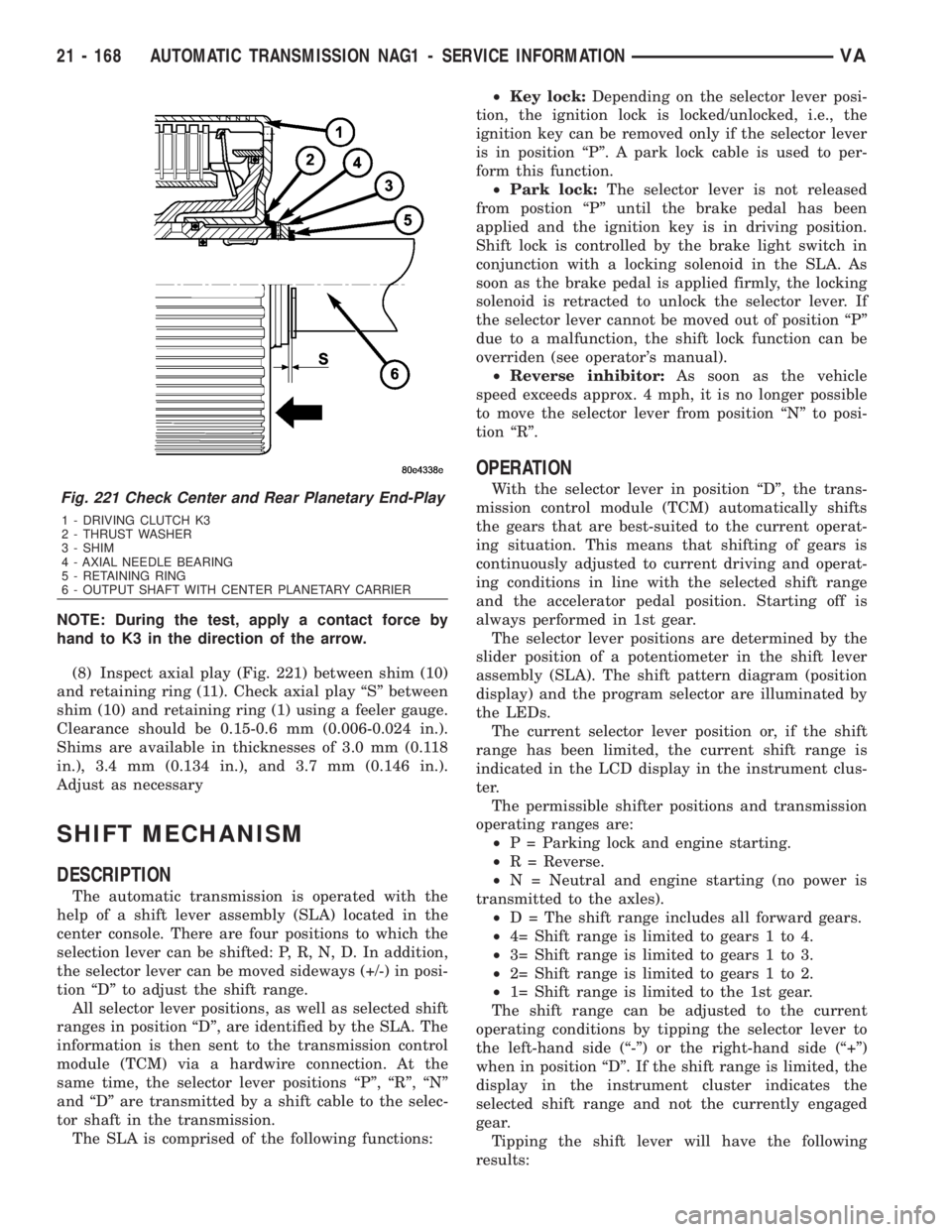
NOTE: During the test, apply a contact force by
hand to K3 in the direction of the arrow.
(8) Inspect axial play (Fig. 221) between shim (10)
and retaining ring (11). Check axial play ªSº between
shim (10) and retaining ring (1) using a feeler gauge.
Clearance should be 0.15-0.6 mm (0.006-0.024 in.).
Shims are available in thicknesses of 3.0 mm (0.118
in.), 3.4 mm (0.134 in.), and 3.7 mm (0.146 in.).
Adjust as necessary
SHIFT MECHANISM
DESCRIPTION
The automatic transmission is operated with the
help of a shift lever assembly (SLA) located in the
center console. There are four positions to which the
selection lever can be shifted: P, R, N, D. In addition,
the selector lever can be moved sideways (+/-) in posi-
tion ªDº to adjust the shift range.
All selector lever positions, as well as selected shift
ranges in position ªDº, are identified by the SLA. The
information is then sent to the transmission control
module (TCM) via a hardwire connection. At the
same time, the selector lever positions ªPº, ªRº, ªNº
and ªDº are transmitted by a shift cable to the selec-
tor shaft in the transmission.
The SLA is comprised of the following functions:²Key lock:Depending on the selector lever posi-
tion, the ignition lock is locked/unlocked, i.e., the
ignition key can be removed only if the selector lever
is in position ªPº. A park lock cable is used to per-
form this function.
²Park lock:The selector lever is not released
from postion ªPº until the brake pedal has been
applied and the ignition key is in driving position.
Shift lock is controlled by the brake light switch in
conjunction with a locking solenoid in the SLA. As
soon as the brake pedal is applied firmly, the locking
solenoid is retracted to unlock the selector lever. If
the selector lever cannot be moved out of position ªPº
due to a malfunction, the shift lock function can be
overriden (see operator's manual).
²Reverse inhibitor:As soon as the vehicle
speed exceeds approx. 4 mph, it is no longer possible
to move the selector lever from position ªNº to posi-
tion ªRº.
OPERATION
With the selector lever in position ªDº, the trans-
mission control module (TCM) automatically shifts
the gears that are best-suited to the current operat-
ing situation. This means that shifting of gears is
continuously adjusted to current driving and operat-
ing conditions in line with the selected shift range
and the accelerator pedal position. Starting off is
always performed in 1st gear.
The selector lever positions are determined by the
slider position of a potentiometer in the shift lever
assembly (SLA). The shift pattern diagram (position
display) and the program selector are illuminated by
the LEDs.
The current selector lever position or, if the shift
range has been limited, the current shift range is
indicated in the LCD display in the instrument clus-
ter.
The permissible shifter positions and transmission
operating ranges are:
²P = Parking lock and engine starting.
²R = Reverse.
²N = Neutral and engine starting (no power is
transmitted to the axles).
²D = The shift range includes all forward gears.
²4= Shift range is limited to gears 1 to 4.
²3= Shift range is limited to gears 1 to 3.
²2= Shift range is limited to gears 1 to 2.
²1= Shift range is limited to the 1st gear.
The shift range can be adjusted to the current
operating conditions by tipping the selector lever to
the left-hand side (ª-º) or the right-hand side (ª+º)
when in position ªDº. If the shift range is limited, the
display in the instrument cluster indicates the
selected shift range and not the currently engaged
gear.
Tipping the shift lever will have the following
results:Fig. 221 Check Center and Rear Planetary End-Play
1 - DRIVING CLUTCH K3
2 - THRUST WASHER
3 - SHIM
4 - AXIAL NEEDLE BEARING
5 - RETAINING RING
6 - OUTPUT SHAFT WITH CENTER PLANETARY CARRIER
21 - 168 AUTOMATIC TRANSMISSION NAG1 - SERVICE INFORMATIONVA
Page 2055 of 2305
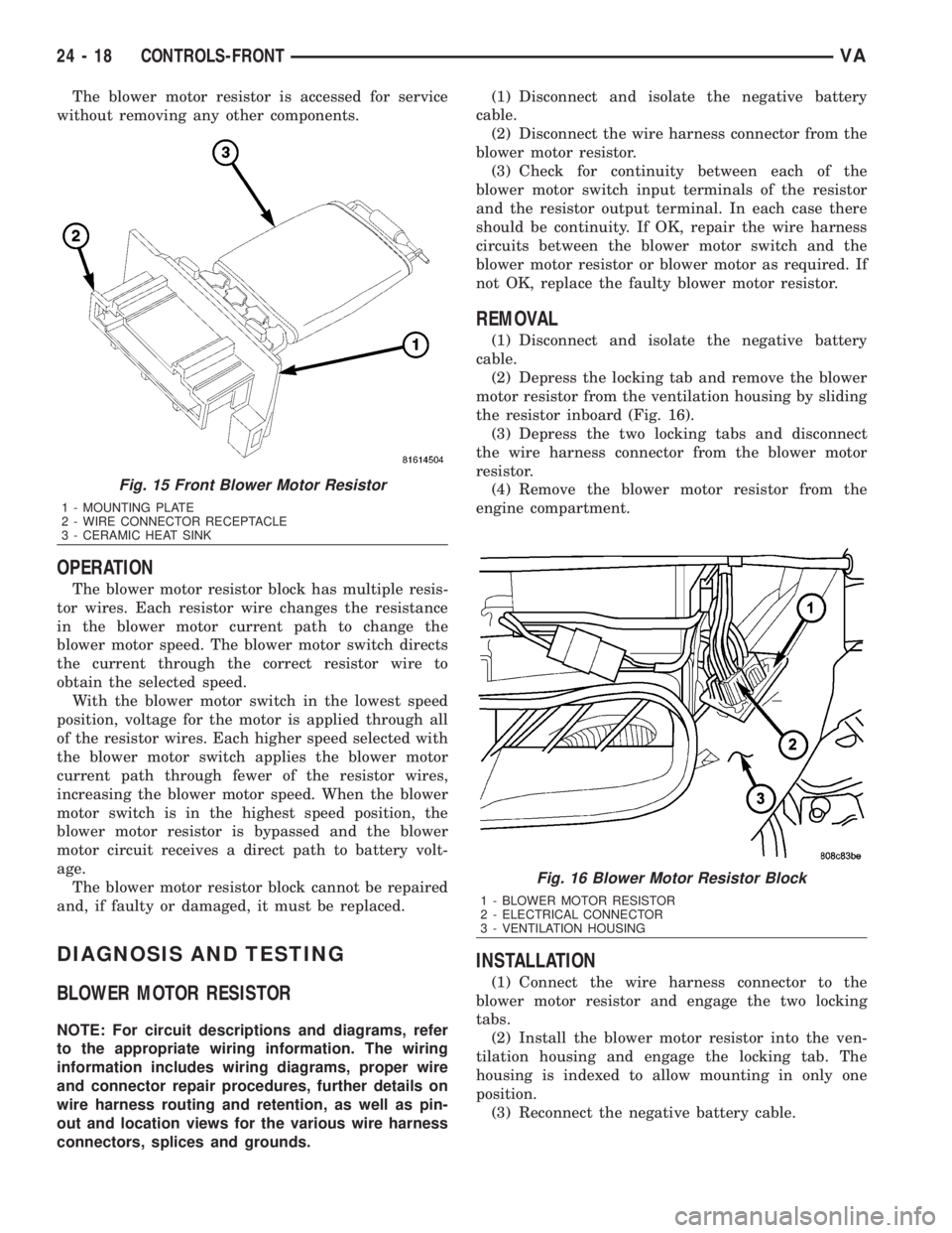
The blower motor resistor is accessed for service
without removing any other components.
OPERATION
The blower motor resistor block has multiple resis-
tor wires. Each resistor wire changes the resistance
in the blower motor current path to change the
blower motor speed. The blower motor switch directs
the current through the correct resistor wire to
obtain the selected speed.
With the blower motor switch in the lowest speed
position, voltage for the motor is applied through all
of the resistor wires. Each higher speed selected with
the blower motor switch applies the blower motor
current path through fewer of the resistor wires,
increasing the blower motor speed. When the blower
motor switch is in the highest speed position, the
blower motor resistor is bypassed and the blower
motor circuit receives a direct path to battery volt-
age.
The blower motor resistor block cannot be repaired
and, if faulty or damaged, it must be replaced.
DIAGNOSIS AND TESTING
BLOWER MOTOR RESISTOR
NOTE: For circuit descriptions and diagrams, refer
to the appropriate wiring information. The wiring
information includes wiring diagrams, proper wire
and connector repair procedures, further details on
wire harness routing and retention, as well as pin-
out and location views for the various wire harness
connectors, splices and grounds.(1) Disconnect and isolate the negative battery
cable.
(2) Disconnect the wire harness connector from the
blower motor resistor.
(3) Check for continuity between each of the
blower motor switch input terminals of the resistor
and the resistor output terminal. In each case there
should be continuity. If OK, repair the wire harness
circuits between the blower motor switch and the
blower motor resistor or blower motor as required. If
not OK, replace the faulty blower motor resistor.
REMOVAL
(1) Disconnect and isolate the negative battery
cable.
(2) Depress the locking tab and remove the blower
motor resistor from the ventilation housing by sliding
the resistor inboard (Fig. 16).
(3) Depress the two locking tabs and disconnect
the wire harness connector from the blower motor
resistor.
(4) Remove the blower motor resistor from the
engine compartment.
INSTALLATION
(1) Connect the wire harness connector to the
blower motor resistor and engage the two locking
tabs.
(2) Install the blower motor resistor into the ven-
tilation housing and engage the locking tab. The
housing is indexed to allow mounting in only one
position.
(3) Reconnect the negative battery cable.
Fig. 15 Front Blower Motor Resistor
1 - MOUNTING PLATE
2 - WIRE CONNECTOR RECEPTACLE
3 - CERAMIC HEAT SINK
Fig. 16 Blower Motor Resistor Block
1 - BLOWER MOTOR RESISTOR
2 - ELECTRICAL CONNECTOR
3 - VENTILATION HOUSING
24 - 18 CONTROLS-FRONTVA
Page 2056 of 2305
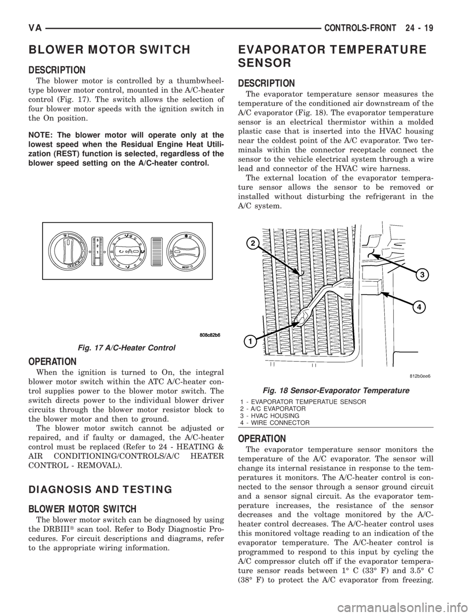
BLOWER MOTOR SWITCH
DESCRIPTION
The blower motor is controlled by a thumbwheel-
type blower motor control, mounted in the A/C-heater
control (Fig. 17). The switch allows the selection of
four blower motor speeds with the ignition switch in
the On position.
NOTE: The blower motor will operate only at the
lowest speed when the Residual Engine Heat Utili-
zation (REST) function is selected, regardless of the
blower speed setting on the A/C-heater control.
OPERATION
When the ignition is turned to On, the integral
blower motor switch within the ATC A/C-heater con-
trol supplies power to the blower motor switch. The
switch directs power to the individual blower driver
circuits through the blower motor resistor block to
the blower motor and then to ground.
The blower motor switch cannot be adjusted or
repaired, and if faulty or damaged, the A/C-heater
control must be replaced (Refer to 24 - HEATING &
AIR CONDITIONING/CONTROLS/A/C HEATER
CONTROL - REMOVAL).
DIAGNOSIS AND TESTING
BLOWER MOTOR SWITCH
The blower motor switch can be diagnosed by using
the DRBIIItscan tool. Refer to Body Diagnostic Pro-
cedures. For circuit descriptions and diagrams, refer
to the appropriate wiring information.
EVAPORATOR TEMPERATURE
SENSOR
DESCRIPTION
The evaporator temperature sensor measures the
temperature of the conditioned air downstream of the
A/C evaporator (Fig. 18). The evaporator temperature
sensor is an electrical thermistor within a molded
plastic case that is inserted into the HVAC housing
near the coldest point of the A/C evaporator. Two ter-
minals within the connector receptacle connect the
sensor to the vehicle electrical system through a wire
lead and connector of the HVAC wire harness.
The external location of the evaporator tempera-
ture sensor allows the sensor to be removed or
installed without disturbing the refrigerant in the
A/C system.
OPERATION
The evaporator temperature sensor monitors the
temperature of the A/C evaporator. The sensor will
change its internal resistance in response to the tem-
peratures it monitors. The A/C-heater control is con-
nected to the sensor through a sensor ground circuit
and a sensor signal circuit. As the evaporator tem-
perature increases, the resistance of the sensor
decreases and the voltage monitored by the A/C-
heater control decreases. The A/C-heater control uses
this monitored voltage reading to an indication of the
evaporator temperature. The A/C-heater control is
programmed to respond to this input by cycling the
A/C compressor clutch off if the evaporator tempera-
ture sensor reads between 1É C (33É F) and 3.5É C
(38É F) to protect the A/C evaporator from freezing.
Fig. 17 A/C-Heater Control
Fig. 18 Sensor-Evaporator Temperature
1 - EVAPORATOR TEMPERATUE SENSOR
2 - A/C EVAPORATOR
3 - HVAC HOUSING
4 - WIRE CONNECTOR
VACONTROLS-FRONT 24 - 19
Page 2058 of 2305
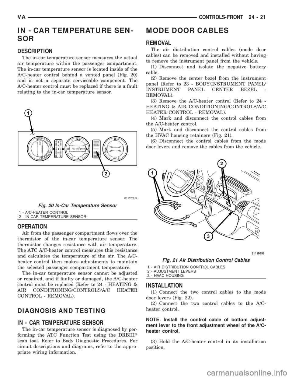
IN - CAR TEMPERATURE SEN-
SOR
DESCRIPTION
The in-car temperature sensor measures the actual
air temperature within the passenger compartment.
The in-car temperature sensor is located inside of the
A/C-heater control behind a vented panel (Fig. 20)
and is not a separate serviceable component. The
A/C-heater control must be replaced if there is a fault
relating to the in-car temperature sensor.
OPERATION
Air from the passenger compartment flows over the
thermistor of the in-car temperature sensor. The
thermistor changes resistance with air temperature.
The ATC A/C-heater control measures this resistance
and calculates the temperature of the air. The A/C-
heater control then makes adjustments to maintain
the selected passenger compartment temperature.
The in-car temperature sensor cannot be adjusted
or repaired, and if faulty or damaged, the A/C-heater
control must be replaced (Refer to 24 - HEATING &
AIR CONDITIONING/CONTROLS/A/C HEATER
CONTROL - REMOVAL).
DIAGNOSIS AND TESTING
IN - CAR TEMPERATURE SENSOR
The in-car temperature sensor is diagnosed by per-
forming the ATC Function Test using the DRBIIIt
scan tool. Refer to Body Diagnostic Procedures. For
circuit descriptions and diagrams, refer to the appro-
priate wiring information.
MODE DOOR CABLES
REMOVAL
The air distribution control cables (mode door
cables) can be removed and installed without having
to remove the instrument panel from the vehicle.
(1) Disconnect and isolate the negative battery
cable.
(2) Remove the center bezel from the instrument
panel (Refer to 23 - BODY/INSTRUMENT PANEL/
INSTRUMENT PANEL CENTER BEZEL -
REMOVAL).
(3) Remove the A/C-heater control (Refer to 24 -
HEATING & AIR CONDITIONING/CONTROLS/A/C
HEATER CONTROL - REMOVAL).
(4) Mark and disconnect the control cables from
the A/C-heater control.
(5) Mark and disconnect the control cables from
the HVAC housing retainers (Fig. 21).
(6) Disconnect the control cables from the mode
door levers and remove the cables from the vehicle.
INSTALLATION
(1) Connect the two control cables to the mode
door levers (Fig. 22).
(2) Connect the two control cables to the A/C-
heater control.
NOTE: Install the control cable of bottom adjust-
ment lever to the front adjustment wheel of the A/C-
heater control.
(3) Hold the A/C-heater control in its installation
position.
Fig. 20 In-Car Temperature Sensor
1 - A/C-HEATER CONTROL
2 - IN-CAR TEMPERATURE SENSOR
Fig. 21 Air Distribution Control Cables
1 - AIR DISTRIBUTION CONTROL CABLES
2 - ADJUSTMENT LEVERS
3 - HVAC HOUSING
VACONTROLS-FRONT 24 - 21
Page 2062 of 2305
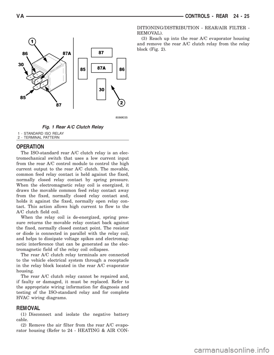
OPERATION
The ISO-standard rear A/C clutch relay is an elec-
tromechanical switch that uses a low current input
from the rear A/C control module to control the high
current output to the rear A/C clutch. The movable,
common feed relay contact is held against the fixed,
normally closed relay contact by spring pressure.
When the electromagnetic relay coil is energized, it
draws the movable common feed relay contact away
from the fixed, normally closed relay contact and,
holds it against the fixed, normally open relay con-
tact. This action allows high current to flow to the
A/C clutch field coil.
When the relay coil is de-energized, spring pres-
sure returns the movable relay contact back against
the fixed, normally closed contact point. The resistor
or diode is connected in parallel with the relay coil,
and helps to dissipate voltage spikes and electromag-
netic interference that can be generated as the elec-
tromagnetic field of the relay coil collapses.
The rear A/C clutch relay terminals are connected
to the vehicle electrical system through a receptacle
in the relay block located in the rear A/C evaporator
housing.
The rear A/C clutch relay cannot be repaired and,
if faulty or damaged, it must be replaced. Refer to
the appropriate wiring information for diagnosis and
testing of the ISO-standard relay and for complete
HVAC wiring diagrams.
REMOVAL
(1) Disconnect and isolate the negative battery
cable.
(2) Remove the air filter from the rear A/C evapo-
rator housing (Refer to 24 - HEATING & AIR CON-DITIONING/DISTRIBUTION - REAR/AIR FILTER -
REMOVAL).
(3) Reach up into the rear A/C evaporator housing
and remove the rear A/C clutch relay from the relay
block (Fig. 2).
Fig. 1 Rear A/C Clutch Relay
1 - STANDARD ISO RELAY
2 - TERMINAL PATTERN
VACONTROLS - REAR 24 - 25