2006 MERCEDES-BENZ SPRINTER diagram
[x] Cancel search: diagramPage 2079 of 2305
the rear A/C control module circuits and radio recep-
tion quality. The suppression filters for the rear
blower motors consist of capacitors and inductance
coils.
The rear blower motor suppression filters cannot
be repaired and, if faulty or damaged, they must be
replaced. Refer to the appropriate wiring information
for complete HVAC wiring diagrams.
REMOVAL
(1) Disconnect and isolate the negative battery
cable.
(2) Remove the cover from the rear A/C evaporator
housing (Refer to 24 - HEATING & AIR CONDI-
TIONING/DISTRIBUTION - REAR/A/C EVAPORA-
TOR COVER-REAR - REMOVAL).
(3) Disconnect the two wire harness connectors
from the rear blower motor suppression filter being
serviced (Fig. 22).
(4) Remove the screw that secures the each rear
blower motor suppression filter to the rear A/C evap-
orator housing and remove the suppression filters as
required.
24 - 42 CONTROLS - REARVA
Page 2081 of 2305
OPERATION
The rear condenser fan suppression filter provides
protection against transient interference signals or
similar interference to the electronic rear condenser
fan circuits which can effect the performance of the
rear A/C control module circuits and radio reception
quality. The suppression filter for the rear condenser
fan consist of capacitors and inductance coils.
The rear condenser fan suppression filter cannot be
repaired and, if faulty or damaged, it must be
replaced. Refer to the appropriate wiring information
for complete HVAC wiring diagrams.
REMOVAL
(1) Disconnect and isolate the negative battery
cable.
(2) Remove the cover from the rear A/C condenser
housing (Refer to 24 - HEATING & AIR CONDI-
TIONING/DISTRIBUTION - REAR/A/C CON-
DENSER COVER-REAR - REMOVAL).
(3) Disconnect the two wire harness connectors
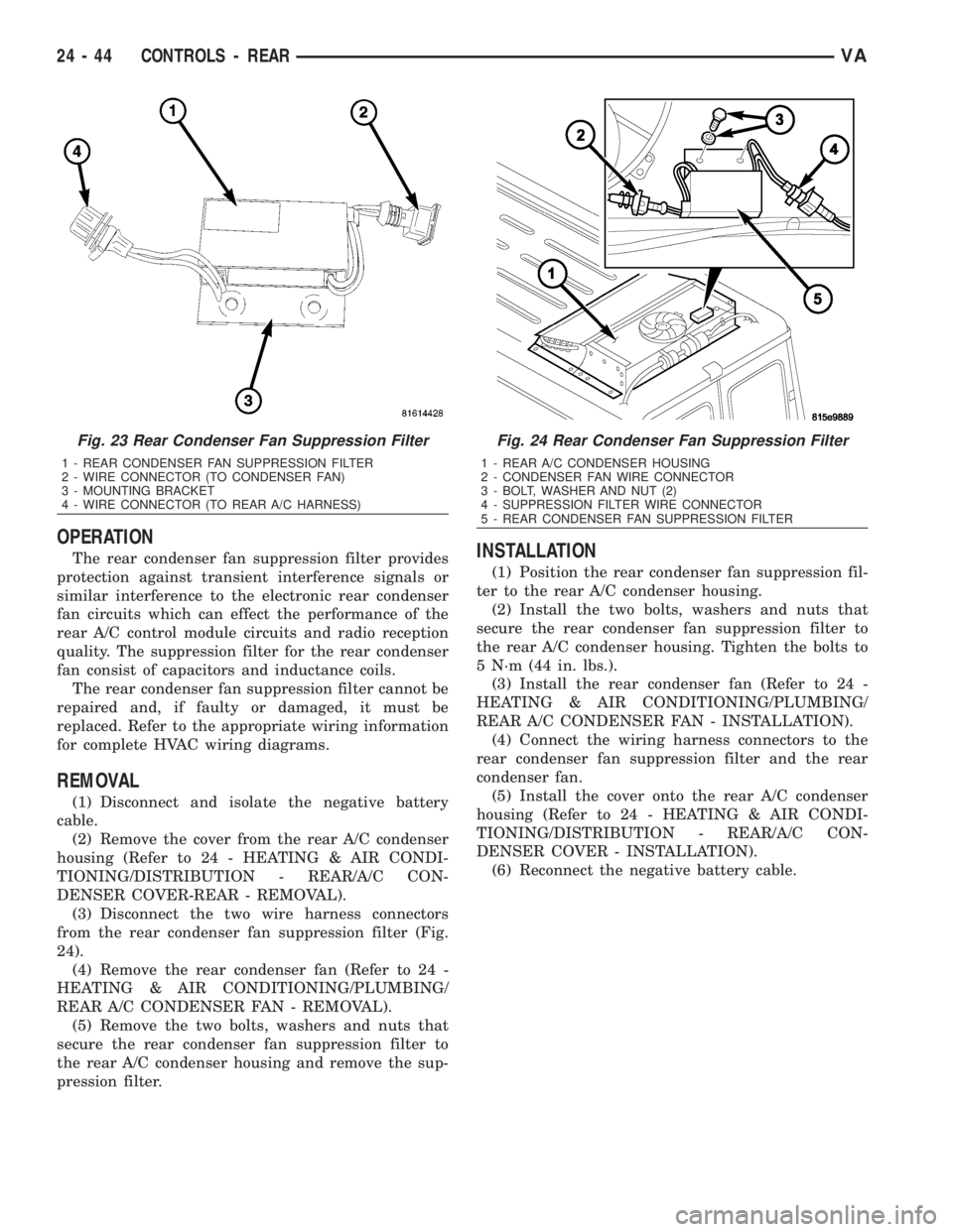
from the rear condenser fan suppression filter (Fig.
24).
(4) Remove the rear condenser fan (Refer to 24 -
HEATING & AIR CONDITIONING/PLUMBING/
REAR A/C CONDENSER FAN - REMOVAL).
(5) Remove the two bolts, washers and nuts that
secure the rear condenser fan suppression filter to
the rear A/C condenser housing and remove the sup-
pression filter.
INSTALLATION
(1) Position the rear condenser fan suppression fil-
ter to the rear A/C condenser housing.
(2) Install the two bolts, washers and nuts that
secure the rear condenser fan suppression filter to
the rear A/C condenser housing. Tighten the bolts to
5 N´m (44 in. lbs.).
(3) Install the rear condenser fan (Refer to 24 -
HEATING & AIR CONDITIONING/PLUMBING/
REAR A/C CONDENSER FAN - INSTALLATION).
(4) Connect the wiring harness connectors to the
rear condenser fan suppression filter and the rear
condenser fan.
(5) Install the cover onto the rear A/C condenser
housing (Refer to 24 - HEATING & AIR CONDI-
TIONING/DISTRIBUTION - REAR/A/C CON-
DENSER COVER - INSTALLATION).
(6) Reconnect the negative battery cable.
Fig. 23 Rear Condenser Fan Suppression Filter
1 - REAR CONDENSER FAN SUPPRESSION FILTER
2 - WIRE CONNECTOR (TO CONDENSER FAN)
3 - MOUNTING BRACKET
4 - WIRE CONNECTOR (TO REAR A/C HARNESS)
Fig. 24 Rear Condenser Fan Suppression Filter
1 - REAR A/C CONDENSER HOUSING
2 - CONDENSER FAN WIRE CONNECTOR
3 - BOLT, WASHER AND NUT (2)
4 - SUPPRESSION FILTER WIRE CONNECTOR
5 - REAR CONDENSER FAN SUPPRESSION FILTER
24 - 44 CONTROLS - REARVA
Page 2159 of 2305
INSIDE HANDLE ACTUATOR......23-33, 23-36
INSTRUMENT CLUSTER................8J-2
INSTRUMENT PANEL ANTENNA CABLE....8A-2
INSTRUMENT PANEL ASSEMBLY........23-59
INSTRUMENT PANEL CENTER BEZEL.....23-57
INSTRUMENT PANEL DUCTS...........24-51
INTAKE AIR PRESSURE SENSOR........14-43
INTAKE AIR TEMPERATURE SENSOR.....14-42
INTAKE MANIFOLD....................9-65
INTERIOR..........................23-70
INTERMEDIATE SHAFT.................19-4
INTERNATIONAL SYMBOLS...............0-9
INTERNATIONAL SYMBOLS...........Intro.-2
INTRUSION SENSOR...................8Q-1
IN - CAR TEMPERATURE SENSOR.......24-21
JUMP STARTING.......................0-6
KEY / LOCK CYLINDER.................19-5
KNUCKLE.............................2-5
LAMPS / LIGHTING - EXTERIOR..........8L-2
LAMPS / LIGHTING - INTERIOR.........8L-28
LATCH RELEASE CABLE...............23-52
LATCH RELEASE HANDLE..............23-52
LATCH STRIKER.....................23-18
LATCH ..................23-18, 23-33, 23-52
LATCH / LOCK CONTROL...............23-38
LATERAL ACCELERATION SENSOR........5-33
LEFT MOUNT.........................9-55
LEVER..............................5-26
LICENSE PLATE BRACKET..............23-48
LICENSE PLATE LAMP BULB...........8L-19
LICENSE PLATE LAMP UNIT............8L-19
LINKAGE............................19-9
LIQUID LINE........................24-77
LOCK CYLINDER.....................23-18
LOW BEAM HEADLAMP BULB..........8L-20
LOW FUEL INDICATOR................8J-19
LOW OIL LEVEL INDICATOR............8J-20
LOWER BALL JOINT....................2-6
LOWER CONTROL ARM.................2-6
LOWER ROLLER ARM.................23-37
MAINTENANCE INDICATOR.............8J-20
MAINTENANCE SCHEDULES..............0-8
MALFUNCTION INDICATOR LAMP (MIL) . . . 8J-21
MANIFOLD AIR FLOW (MAF) SENSOR....14-44
MASTER CYLINDER...................5-17
MASTER LOCK SWITCH................8N-1
METRIC SYSTEM...................Intro.-6
MODE DOOR CABLES.................24-21
MULTI - FUNCTION INDICATOR..........8J-22
MULTI - FUNCTION SWITCH............8L-21
O2 SENSOR.........................14-45
ODOMETER.........................8J-22
OIL COOLER & LINES..................9-56
OIL FILTER ..........................9-57
OIL JET .............................9-57
OIL PAN .............................9-58
OIL PUMP...........................9-61
OIL PUMP.........................21-154
OIL SENSOR.........................9-64
OIL ................................9-56
OPENING DIMENSIONS................23-93
OUTPUT SHAFT BEARING.............21-156
OUTPUT SHAFT SEAL................21-159
PAINT TOUCH - UP...................23-77
PAINT.............................23-77
PARK BRAKE INDICATOR..............8J-23
PARK BRAKE SWITCH.................8L-21
PARK LOCK CABLE..................21-160
PARKING BRAKE......................5-23
PASSENGER AIRBAG BRACKET.........8O-27
PASSENGER AIRBAG.................8O-24
PASSENGER HEATED SEAT SWITCH.....8G-13
PEDAL..............................5-19
PISTON & CONNECTING ROD............9-45
PISTON RINGS.......................9-52
PISTONS..........................21-163
PLANETARY GEARTRAIN..............21-164
PLUMBING.........................24-61
POWER BRAKE BOOSTER...............5-19
POWER DISTRIBUTION CENTER.......8W-97-3
POWER DISTRIBUTION..............8W-97-1
POWER MIRROR SWITCH..............8N-3
POWER MIRRORS....................8N-3
POWER OUTLET
...................8W-97-3
POWER WINDOW SWITCH
..............8N-5
POWER WINDOWS
....................8N-5
PROP ROD
.........................23-53
PROPELLER SHAFT
.................3-1, 3-7PUMP.............................19-11
QUARTER TRIM PANEL................23-74
QUARTER WINDOW..................23-84
RADIATOR CROSSMEMBER............23-49
RADIATOR FAN.......................7-14
RADIATOR PRESSURE CAP..............7-19
RADIATOR...........................7-17
RADIO..............................8A-2
RAIN SENSOR CONTROL MODULE......8R-15
RAIN SENSOR.......................8R-12
REAR AXLE..........................3-12
REAR A / C CONDENSER FAN...........24-83
REAR A / C EVAPORATOR..............24-84
REAR A / C EXPANSION VALVE..........24-85
REAR BUMPER - STEP.................13-2
REAR CROSSMEMBER - TRANSMISSION . . 13-11
REAR DISCHARGE LINE...............24-88
REAR FASCIA........................13-3
REAR LATCH STRIKER................23-40
REAR LATCH........................23-40
REAR LIQUID LINE...................24-91
REAR RECEIVER / DRIER..............24-94
REAR REFRIGERANT RESERVOIR........24-95
REAR SEAT BACK SHIELD..............23-82
REAR SEAT BELT & RETRACTOR........8O-28
REAR SEAT BELT BUCKLE.............8O-30
REAR SIDE MARKER LAMP BULB.......8L-22
REAR SUCTION LINE..................24-96
REAR TURN LAMP BULB..............8L-23
REAR VIEW MIRROR.................23-75
REAR WHEEL SPEED SENSOR...........5-31
REAR WINDOW DEFOGGER GRID........8G-7
REAR WINDOW DEFOGGER RELAY.......8G-3
REAR WINDOW DEFOGGER SWITCH......8G-4
REAR...............................2-11
RECEIVER / DRIER...................24-79
RECIRCULATION DOOR ACTUATOR......24-22
REFRIGERANT LINE COUPLER..........24-98
REFRIGERANT OIL...................24-81
REFRIGERANT.......................24-80
RELAY...........................8W-97-4
REMOTE KEYLESS ENTRY
TRANSMITTER.......................8N-1
REPEATER LAMP BULB................8L-23
REPEATER LAMP UNIT................8L-24
RESTRAINTS.........................8O-2
RIGHT MOUNT.......................9-56
ROTORS............................5-20
SAFETY LATCH......................23-53
SEAL - PINION........................3-39
SEAT ADJUSTERS - FRONT.............23-81
SEAT BACK CUSHION / COVER - REAR....23-82
SEAT BACK - FRONT..................23-80
SEAT BELT SWITCH..................8O-31
SEAT BELT TENSIONER................8O-32
SEAT BELT TURNING LOOP ADJUSTER . . . 8O-33
SEAT CUSHION - FRONT...............23-80
SEAT CUSHION / COVER - REAR.........23-83
SEATBELT INDICATOR.................8J-24
SEAT - FRONT.......................23-79
SEAT - REAR........................23-81
SECURITY SYSTEM MODULE............8Q-2
SENTRY KEY REMOTE ENTRY MODULE....8Q-2
SERVO..............................8P-2
SHAFT - AXLE DUAL REAR WHEELS......3-27
SHAFT - AXLE SINGLE REAR WHEEL......3-23
SHIFT MECHANISM..................21-168
SHOCK..............................2-13
SHOES..............................5-27
SIDE CURTAIN AIRBAG................8O-35
SIDE IMPACT SENSOR................8O-39
SIDE VIEW MIRROR..................23-49
SIDE VIEW MIRROR - GLASS...........23-50
SIREN..............................8Q-4
SLIDING DOOR......................23-40
SOLENOID.........................21-171
SPARE TIRE CARRIER.................22-12
SPEAKER............................8A-2
SPEED CONTROL.....................8P-1
SPEEDOMETER......................8J-25
SPRING CLAMP PLATES.................2-8
SPRING SHACKLE.....................2-15
SPRING STOP PLATES..................2-9
SPRING
.........................2-7, 2-14
STABILIZER BAR
..................2-9, 2-15
STABILIZER LINK
.................2-10, 2-16
STABILIZER
.........................23-45
STARTER MOTOR RELAY
..............8F-35STARTER MOTOR....................8F-33
STARTING SYSTEM...................8F-28
STEERING ANGLE SENSOR..............5-32
STEERING COLUMN OPENING COVER....23-68
STEERING WHEEL.....................19-6
STEERING...........................19-1
STEPWELL SCUFF PADS...............23-75
STRUT..............................2-10
SUCTION LINE.......................24-81
SUN VISOR.........................23-76
SUPPORT PLATE......................5-23
SUPPRESSOR FILTER - REAR BLOWER
MOTOR............................24-41
SUPPRESSOR FILTER - REAR
CONDENSER FAN....................24-43
SWITCH.............................8P-3
TACHOMETER.......................8J-25
TAIL LAMP UNIT.....................8L-25
TAILPIPE............................11-3
TEMPERATURE CONTROL..............24-38
TEMPERATURE SENSOR...............24-40
TEMPERATURE SENSOR / PARK -
NEUTRAL CONTACT..................21-176
TERMINAL........................Intro.-10
THREADED HOLE REPAIR.............Intro.-6
TIE ROD END ........................19-10
TIME DELAY RELAY....................8L-35
TIMING CHAIN AND SPROCKETS.........9-72
TIMING CHAIN COVER.................9-70
TIMING CHAIN TENSIONER..............9-81
TIRES..............................22-7
TIRES / WHEELS......................22-1
TONE WHEEL........................5-32
TOP COVER.........................23-67
TOP COVER - CLUSTER................23-64
TOP COVER - TRAY...................23-65
TORQUE CONVERTER HUB SEAL.......21-184
TORQUE CONVERTER................21-178
TORQUE REFERENCES...............Intro.-9
TOWING.............................0-7
TRACTION CONTROL INDICATOR........8J-26
TRACTION CONTROL MALFUNCTION
INDICATOR.........................8J-27
TRAILER HITCH......................13-11
TRANSMISSION CONTROL MODULE......8E-6
TRANSPONDER KEY...................8Q-5
TRIM PANEL.............23-18, 23-34, 23-46
TURBOCHARGER SYSTEM..............11-3
TURBOCHARGER......................11-6
TURN SIGNAL INDICATOR..............8J-27
TURN SIGNAL RELAY.................8L-26
UNDERBODY LINES..................24-100
UPPER ROLLER ARM.................23-36
VACUUM PUMP.......................9-54
VALVE COOLER.......................25-6
VALVE SPRINGS......................9-35
VALVE STEM SEALS...................9-34
VALVE ..............................25-5
VEHICLE IDENTIFICATION NUMBER.....Intro.-1
VEHICLE THEFT SECURITY..............8Q-1
VIBRATION DAMPER...................9-53
VOLTAGE REGULATOR.................8F-24
WAIT - TO - START INDICATOR..........8J-28
WASHER FLUID INDICATOR............8J-29
WASHER FLUID LEVEL SWITCH.........8R-16
WASHER HOSES / TUBES..............8R-18
WASHER NOZZLE....................8R-18
WASHER PUMP / MOTOR..............8R-19
WASHER RESERVOIR.................8R-21
WATER IN FUEL SENSOR..............14-30
WATER PUMP........................7-20
WATER VALVE .......................24-83
WATER - IN - FUEL INDICATOR..........8J-29
WHEEL ALIGNMENT...................2-17
WHEELS...........................22-13
WINDOW MOTOR.....................8N-5
WINDOW REGULATOR - MANUAL........23-21
WINDOW REGULATOR - POWER........23-20
WINDSHIELD........................23-85
WIPER ARM........................8R-23
WIPER BLADE.......................8R-26
WIPER LINKAGE.....................8R-28
WIPER MOTOR......................8R-31
WIPER RELAY.......................8R-34
WIPERS/WASHERS....................8R-2
WIRING DIAGRAM INFORMATION......Intro.-1
YAW RATE SENSOR...................5-35
2 INDEXVA
Description Group-Page Description Group-Page Description Group-Page
Page 2164 of 2305
TABLE OF CONTENTS - Continued
SYSTEM UNDERVOLTAGE..............................................109
TCC OVER TEMP......................................................111
TCC SOLENOID CIRCUIT...............................................112
TCC STUCK ON.......................................................115
TRANS TEMP SENSOR - P/N SWITCH CIRCUIT............................117
TRANS TEMP SENSOR ERRATIC........................................120
TRANS TEMP SENSOR SHORTED.......................................122
TRANSMISSION SLIPPING..............................................125
VERIFICATION TESTS
VERIFICATION TESTS..................................................127
8.0 COMPONENT LOCATIONS..............................................129
8.1ENGINE CONTROL MODULE.......................................129
8.2TRANSMISSION CONTROL MODULE................................129
8.3TRANSMISSION SOLENOID ASSEMBLY..............................129
9.0 CONNECTOR PINOUTS................................................131
ELECTROHYDRAULIC CONTROL UNIT - BLACK...........................131
SHIFTER ASSEMBLY - BLACK...........................................131
TRANSMISSION CONTROL MODULE C1 - BLACK..........................131
TRANSMISSION CONTROL MODULE C2 - BLACK..........................132
TRANSMISSION RELAY (RELAY BLOCK)..................................133
10.0 SCHEMATIC DIAGRAMS................................................135
11.0 CHARTS AND GRAPHS................................................137
11.15 VOLT SQUARE WAVE ± TYPICAL PATTERN.........................137
11.2TRANSMISSION TEMP SENSOR....................................138
iii
Page 2175 of 2305
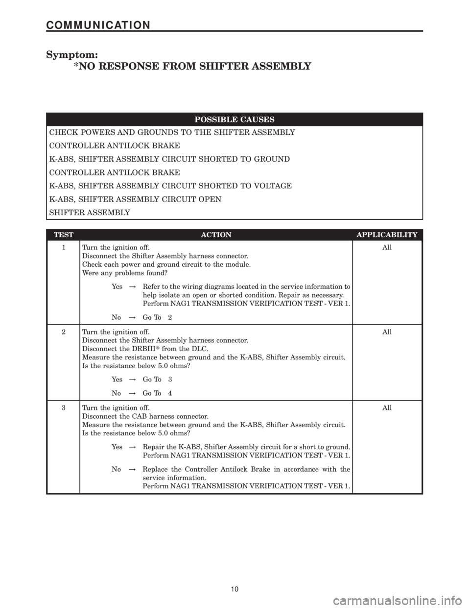
Symptom:
*NO RESPONSE FROM SHIFTER ASSEMBLY
POSSIBLE CAUSES
CHECK POWERS AND GROUNDS TO THE SHIFTER ASSEMBLY
CONTROLLER ANTILOCK BRAKE
K-ABS, SHIFTER ASSEMBLY CIRCUIT SHORTED TO GROUND
CONTROLLER ANTILOCK BRAKE
K-ABS, SHIFTER ASSEMBLY CIRCUIT SHORTED TO VOLTAGE
K-ABS, SHIFTER ASSEMBLY CIRCUIT OPEN
SHIFTER ASSEMBLY
TEST ACTION APPLICABILITY
1 Turn the ignition off.
Disconnect the Shifter Assembly harness connector.
Check each power and ground circuit to the module.
Were any problems found?All
Ye s!Refer to the wiring diagrams located in the service information to
help isolate an open or shorted condition. Repair as necessary.
Perform NAG1 TRANSMISSION VERIFICATION TEST - VER 1.
No!Go To 2
2 Turn the ignition off.
Disconnect the Shifter Assembly harness connector.
Disconnect the DRBIIItfrom the DLC.
Measure the resistance between ground and the K-ABS, Shifter Assembly circuit.
Is the resistance below 5.0 ohms?All
Ye s!Go To 3
No!Go To 4
3 Turn the ignition off.
Disconnect the CAB harness connector.
Measure the resistance between ground and the K-ABS, Shifter Assembly circuit.
Is the resistance below 5.0 ohms?All
Ye s!Repair the K-ABS, Shifter Assembly circuit for a short to ground.
Perform NAG1 TRANSMISSION VERIFICATION TEST - VER 1.
No!Replace the Controller Antilock Brake in accordance with the
service information.
Perform NAG1 TRANSMISSION VERIFICATION TEST - VER 1.
10
COMMUNICATION
Page 2177 of 2305
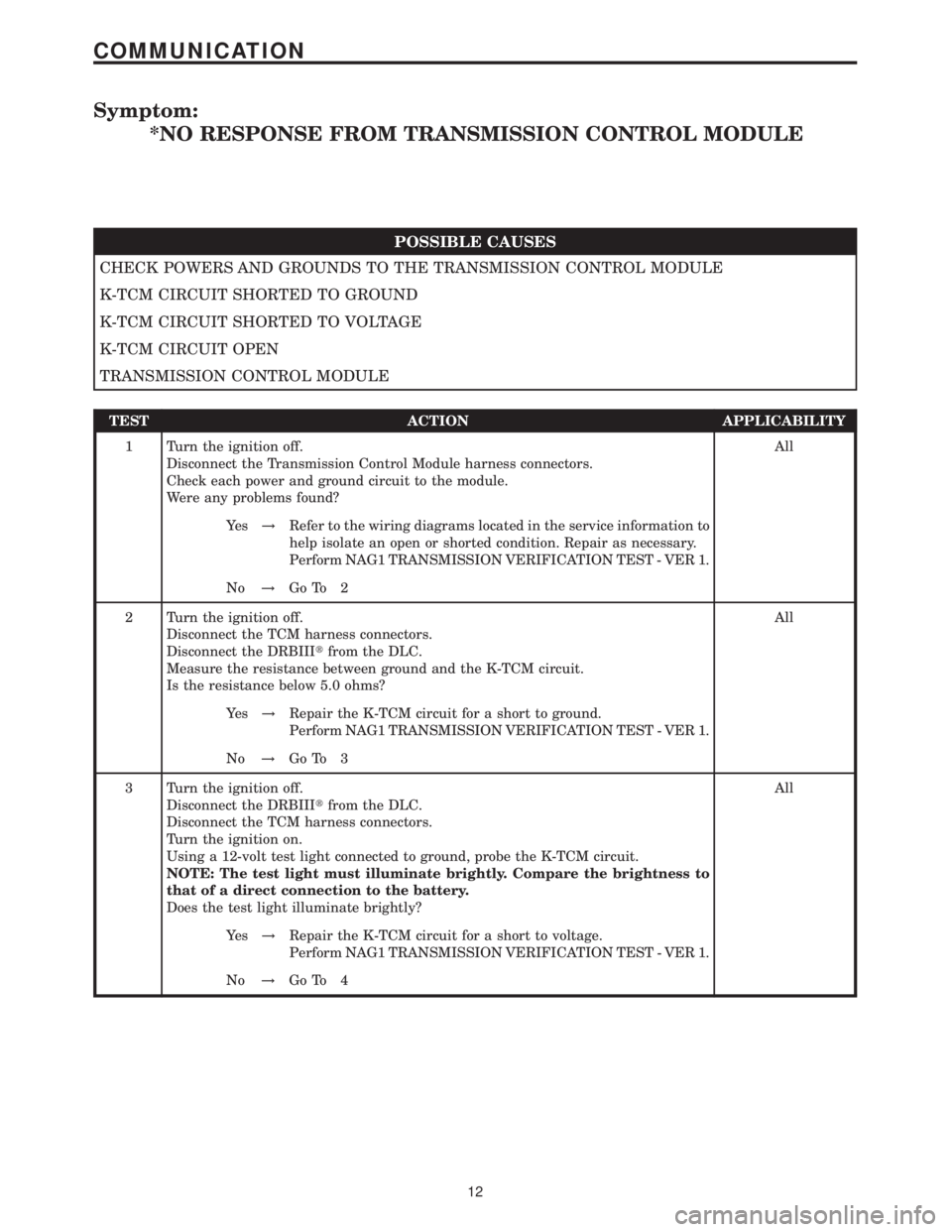
Symptom:
*NO RESPONSE FROM TRANSMISSION CONTROL MODULE
POSSIBLE CAUSES
CHECK POWERS AND GROUNDS TO THE TRANSMISSION CONTROL MODULE
K-TCM CIRCUIT SHORTED TO GROUND
K-TCM CIRCUIT SHORTED TO VOLTAGE
K-TCM CIRCUIT OPEN
TRANSMISSION CONTROL MODULE
TEST ACTION APPLICABILITY
1 Turn the ignition off.
Disconnect the Transmission Control Module harness connectors.
Check each power and ground circuit to the module.
Were any problems found?All
Ye s!Refer to the wiring diagrams located in the service information to
help isolate an open or shorted condition. Repair as necessary.
Perform NAG1 TRANSMISSION VERIFICATION TEST - VER 1.
No!Go To 2
2 Turn the ignition off.
Disconnect the TCM harness connectors.
Disconnect the DRBIIItfrom the DLC.
Measure the resistance between ground and the K-TCM circuit.
Is the resistance below 5.0 ohms?All
Ye s!Repair the K-TCM circuit for a short to ground.
Perform NAG1 TRANSMISSION VERIFICATION TEST - VER 1.
No!Go To 3
3 Turn the ignition off.
Disconnect the DRBIIItfrom the DLC.
Disconnect the TCM harness connectors.
Turn the ignition on.
Using a 12-volt test light connected to ground, probe the K-TCM circuit.
NOTE: The test light must illuminate brightly. Compare the brightness to
that of a direct connection to the battery.
Does the test light illuminate brightly?All
Ye s!Repair the K-TCM circuit for a short to voltage.
Perform NAG1 TRANSMISSION VERIFICATION TEST - VER 1.
No!Go To 4
12
COMMUNICATION
Page 2190 of 2305
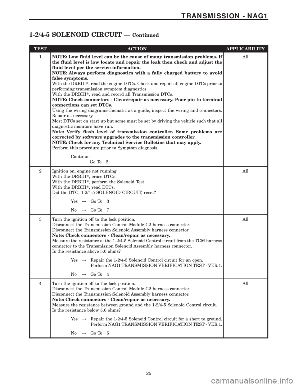
TEST ACTION APPLICABILITY
1NOTE: Low fluid level can be the cause of many transmission problems. If
the fluid level is low locate and repair the leak then check and adjust the
fluid level per the service information.
NOTE: Always perform diagnostics with a fully charged battery to avoid
false symptoms.
With the DRBIIIt, read the engine DTCs. Check and repair all engine DTCs prior to
performing transmission symptom diagnostics.
With the DRBIIIt, read and record all Transmission DTCs.
NOTE: Check connectors - Clean/repair as necessary. Poor pin to terminal
connections can set DTCs.
Using the wiring diagram/schematic as a guide, inspect the wiring and connectors.
Repair as necessary.
Most DTCs set on start up but some must be set by driving the vehicle such that all
diagnostic monitors have run.
Note: Verify flash level of transmission controller. Some problems are
corrected by software upgrades to the transmission controller.
NOTE: Check for any Technical Service Bulletins that may apply.
Perform this procedure prior to Symptom diagnosis.All
Continue
Go To 2
2 Ignition on, engine not running.
With the DRBIIIt, erase DTCs.
With the DRBIIIt, perform the Solenoid Test.
With the DRBIIIt, read DTCs.
Did the DTC, 1-2/4-5 SOLENOID CIRCUIT, reset?All
Ye s!Go To 3
No!Go To 7
3 Turn the ignition off to the lock position.
Disconnect the Transmission Control Module C2 harness connector.
Disconnect the Transmission Solenoid Assembly harness connector
Note: Check connectors - Clean/repair as necessary.
Measure the resistance of the 1-2/4-5 Solenoid Control circuit from the TCM harness
connector to the Transmission Solenoid Assembly harness connector.
Is the resistance above 5.0 ohms?All
Ye s!Repair the 1-2/4-5 Solenoid Control circuit for an open.
Perform NAG1 TRANSMISSION VERIFICATION TEST - VER 1.
No!Go To 4
4 Turn the ignition off to the lock position.
Disconnect the Transmission Control Module C2 harness connector.
Disconnect the Transmission Solenoid Assembly harness connector.
Note: Check connectors - Clean/repair as necessary.
Measure the resistance between ground and the 1-2/4-5 Solenoid Control circuit.
Is the resistance below 5.0 ohms?All
Ye s!Repair the 1-2/4-5 Solenoid Control circuit for a short to ground.
Perform NAG1 TRANSMISSION VERIFICATION TEST - VER 1.
No!Go To 5
25
TRANSMISSION - NAG1
1-2/4-5 SOLENOID CIRCUIT ÐContinued
Page 2193 of 2305

TEST ACTION APPLICABILITY
1NOTE: Low fluid level can be the cause of many transmission problems. If
the fluid level is low locate and repair the leak then check and adjust the
fluid level per the service information.
NOTE: Always perform diagnostics with a fully charged battery to avoid
false symptoms.
With the DRBIIIt, read the engine DTCs. Check and repair all engine DTCs prior to
performing transmission symptom diagnostics.
With the DRBIIIt, read and record all Transmission DTCs.
NOTE: Check connectors - Clean/repair as necessary. Poor pin to terminal
connections can set DTCs.
Using the wiring diagram/schematic as a guide, inspect the wiring and connectors.
Repair as necessary.
Most DTCs set on start up but some must be set by driving the vehicle such that all
diagnostic monitors have run.
Note: Verify flash level of transmission controller. Some problems are
corrected by software upgrades to the transmission controller.
NOTE: Check for any Technical Service Bulletins that may apply.
Perform this procedure prior to Symptom diagnosis.All
Continue
Go To 2
2 Ignition on, engine not running.
With the DRBIIIt, erase DTCs.
With the DRBIIIt, perform the Solenoid Test.
With the DRBIIIt, read DTCs.
Did the DTC, 2-3 SOLENOID CIRCUIT, reset?All
Ye s!Go To 3
No!Go To 7
3 Turn the ignition off to the lock position.
Disconnect the Transmission Control Module C2 harness connector.
Disconnect the Transmission Solenoid Assembly harness connector
Note: Check connectors - Clean/repair as necessary.
Measure the resistance of the 2-3 Solenoid Control circuit from the TCM C2 harness
connector to the Transmission Solenoid Assembly harness connector.
Is the resistance above 5.0 ohms?All
Ye s!Repair the 2-3 Solenoid Control circuit for an open.
Perform NAG1 TRANSMISSION VERIFICATION TEST - VER 1.
No!Go To 4
4 Turn the ignition off to the lock position.
Disconnect the Transmission Control Module C2 harness connector.
Disconnect the Transmission Solenoid Assembly harness connector.
Note: Check connectors - Clean/repair as necessary.
Measure the resistance between ground and the 2-3 Solenoid Control circuit.
Is the resistance below 5.0 ohms?All
Ye s!Repair the 2-3 Solenoid Control circuit for a short to ground.
Perform NAG1 TRANSMISSION VERIFICATION TEST - VER 1.
No!Go To 5
28
TRANSMISSION - NAG1
2-3 SOLENOID CIRCUIT ÐContinued