2006 MERCEDES-BENZ SPRINTER roof rack
[x] Cancel search: roof rackPage 951 of 2305
REAR TURN LAMP BULB
REMOVAL.............................23
INSTALLATION.........................23
REPEATER LAMP BULB
REMOVAL.............................23
INSTALLATION.........................24
REPEATER LAMP UNIT
REMOVAL.............................24INSTALLATION.........................25
TAIL LAMP UNIT
REMOVAL.............................25
INSTALLATION.........................26
TURN SIGNAL RELAY
REMOVAL.............................26
INSTALLATION.........................26
LAMPS / LIGHTING - EXTE-
RIOR
DESCRIPTION
The exterior lighting system for this model
includes the following exterior lamps:
²Backup Lamps- The backup (or reverse) lamps
are integral to the tail lamp units mounted to the
back of the quarter panel on each side of the tailgate
at the rear of the vehicle.
²Brake Lamps- The brake (or stop) lamps
include a bulb and reflector that are integral to the
tail lamp units mounted to the back of the quarter
panel on each side of the tailgate opening, and the
Center High Mounted Stop Lamp (CHMSL) that is
centered on the rear edge of the roof panel above the
tailgate opening.
²Daytime Running Lamps- Vehicles manufac-
tured for sale in Canada have a Daytime Running
Lamps (DRL) relay that illuminates the low beam
headlamp bulbs whenever the engine is running.
²Fog Lamps- Fog lamp bulbs and reflectors are
included in both front lamp units of vehicles
equipped with this option.
²Hazard Warning Lamps- The hazard warning
lamps include all of the right and left turn signal and
repeater lamps.
²Headlamps- Separate low beam and high
beam headlamp bulbs are installed in the front lamp
unit on each side of the front grille opening. A head-
lamp leveling actuator motor is also integral to each
front lamp unit.
²Park Lamps- The park lamps include the front
park/side marker lamps and front position lamps
that are integral to the front lamp units mounted on
either side of the front grille opening, as well as the
rear park lamps and rear side marker lamps that are
integral to the tail lamp units mounted to the back of
the quarter panel on each side of the tailgate open-
ing. Included in the park lamps circuit are two rear
license plate lamp units mounted on the left rear
tailgate door. The park lamps may also include
optional clearance lamps, which are located on each
side of a vehicle that is so equipped.
²Turn Signal Lamps- The turn signal lamps
include the front turn lamps that are integral to the
front lamp units, the rear turn lamps that are inte-
gral to the tail lamp units, and a repeater lampmounted to each front fender just above the front
wheel opening.
Other components of the exterior lighting system
for this model include:
²Brake Lamp Switch- A plunger-type brake
lamp switch is located on the steering column sup-
port bracket under the instrument panel and actu-
ated by the brake pedal arm.
²Daytime Running Lamp Relays- Vehicles
manufactured for sale in Canada have two Daytime
Running Lamps (DRL) relays. Dedicated right and
left side relays illuminate the low beam headlamp
bulb installed in each front lamp unit whenever the
engine is running. These relays are located in dedi-
cated vehicle wire harness connectors within the
driver side front seat riser.
²Fog Lamp Relay- Vehicles equipped with the
optional fog lamps have a fog lamp relay located in a
dedicated vehicle wire harness connector within the
driver side front seat riser.
²Fog Lamp Switch- A fog lamp switch is
mounted in the instrument cluster bezel, below the
cluster and outboard of the steering column on vehi-
cles equipped with this option.
²Headlamp Leveling Motor- A headlamp lev-
eling actuator motor is located on the back of each
headlamp housing and adjusts both the low beam
headlamp, high beam headlamp, and fog lamp (if
equipped) reflector frames in unison.
²Headlamp Leveling Switch- A thumbwheel
actuated headlamp leveling switch is mounted in the
instrument cluster bezel, below the cluster and out-
board of the steering column.
²Multi-Function Switch- The multi-function
switch is located on the top of the steering column,
just below the steering wheel. The multi-function
switch is connected directly to the fuse block located
below the steering column through an integral inter-
face connector. Only the left (lighting), right (wiper)
control stalks and the hazard warning switch button
for the multi-function switch are visible, the remain-
der of the switch is concealed beneath the steering
column shrouds. The multi-function switch includes a
left (lighting) control stalk and a right (wiper) control
stalk. The left control stalk is dedicated to providing
almost all of the driver controls for the exterior light-
ing system.
²Trailer Tow Connector- Vehicles equipped
with a factory-approved, field-installed trailer towing
8L - 2 LAMPS/LIGHTING - EXTERIORVA
Page 994 of 2305

travelling end-release seat belt buckles secured to
the inboard seat track. The driver side front seat belt
buckle of all models includes an integral seat belt
switch that detects whether its seat belt has been
fastened.
²Rear Seat Belts- All rear seating positions are
equipped with three-point seat belt systems. Each
rear seating position belt employs an integral seat
cushion frame mounted inertia latch-type retractor, a
fixed position upper seat back frame mounted turn-
ing loop, and a fixed lower seat belt anchor secured
to the seat cushion frame. All rear seat belts have
fixed end-release seat belt buckles that are also
secured to the seat cushion frame.
PASSIVE RESTRAINTS
A Next Generation driver airbag is standard facto-
ry-installed safety equipment on this model, while a
passenger side front airbag and side curtain airbags
are optional. This airbag system is a passive, inflat-
able, Supplemental Restraint System (SRS) and vehi-
cles with this equipment can be readily identified by
the ªSRS - AIRBAGº logo molded into the driver air-
bag trim cover in the center of the steering wheel
and, if the vehicle is so equipped, also into the pas-
senger airbag door on the instrument panel above
the glove box (Fig. 2). Vehicles with the airbag sys-
tem can also be identified by the airbag indicator,
which will illuminate in the instrument cluster for
about six seconds as a bulb test each time the igni-
tion switch is turned to the On position. A pyrotech-
nic-type seat belt tensioner is integral to the front
seat belt retractor mounted on the lower B-pillar on
the driver side, and to the passenger side retractor of
vehicles equipped with the optional passenger side
airbag.
The supplemental restraint system includes the
following major components, which are described in
further detail elsewhere in this service information:²Airbag Control Module- The Airbag Control
Module (ACM) is located on a mount on the floor
panel within the driver side seat riser, beneath the
driver seat in the passenger compartment.
²Airbag (SRS) Indicator- The airbag indicator
is integral to the ElectroMechanical Instrument Clus-
ter (EMIC), which is located on the instrument panel
in front of the driver.
²Clockspring- The clockspring is located near
the top of the steering column, directly beneath the
steering wheel.
²Driver Airbag- The driver airbag is located in
the center of the steering wheel, beneath the driver
airbag trim cover.
²Driver Knee Blocker- The structure of the
lower instrument panel serves as a knee blocker for
the driver.
²Passenger Airbag- The optional passenger air-
bag is located within the instrument panel, behind
the passenger airbag door on the instrument panel
above the glove box on the passenger side of the vehi-
cle.
²Passenger Knee Blocker- The structure of
the glove box door and the lower instrument panel
serve as a knee blocker for the front seat passenger.
²Seat Belt Tensioner- A seat belt tensioner is
integral to the driver side front seat belt retractor
unit, and to the passenger side front seat belt retrac-
tor unit on vehicles equipped with an optional pas-
senger airbag.
²Side Curtain Airbags- Optional side curtain
airbags are available for this model when it is also
equipped with dual front airbags. In vehicles
equipped with this option, a side curtain airbag is
located on the inside of the roof side rail within a
garnish molding that extends from the A-pillar to the
B-pillar above each front door opening within the
passenger compartment of the vehicle.
²Side Impact Sensor- Two side impact sensors
are used on vehicles equipped with the optional side
curtain airbags, one on each side of the vehicle. One
sensor is located near the front of each front door
step well, concealed behind the step well trim.
The ACM contains a central processing unit and
programming that allows it to communicate on a
serial data bus diagnostic circuit connected to the
16-way Data Link Connector (DLC) located below the
left end of the instrument panel. This method of com-
munication is used for initialization of the ACM and
for diagnosis of the SRS circuits and components
using a diagnostic scan tool.
Hard wired circuitry connects the supplemental
restraint system components to each other through
the electrical system of the vehicle. These hard wired
circuits are integral to several wire harnesses, which
are routed throughout the vehicle and retained by
many different methods. These circuits may be con-
nected to each other, to the vehicle electrical system,
Fig. 2 SRS Logo
VARESTRAINTS 8O - 3
Page 1026 of 2305
(8) Remove the seat belt turning loop height
adjuster from the inner B-pillar.
INSTALLATION
WARNING: To avoid personal injury or death, on
vehicles equipped with airbags, disable the supple-
mental restraint system before attempting any
steering wheel, steering column, airbag, seat belt
tensioner, or instrument panel component diagno-
sis or service. Disconnect and isolate the battery
negative (ground) cable, then wait two minutes for
the system capacitor to discharge before perform-
ing further diagnosis or service. This is the only
sure way to disable the supplemental restraint sys-
tem. Failure to take the proper precautions could
result in accidental airbag deployment.
WARNING: To avoid personal injury or death, during
and following any seat belt service, carefully
inspect all seat belts, buckles, mounting hardware,
retractors, and anchors for proper installation, oper-
ation, or damage. Replace any belt that is cut,
frayed, or torn. Straighten any belt that is twisted.
Tighten any loose fasteners. Replace any belt that
has a damaged or inoperative buckle or retractor.
Replace any belt that has a bent or damaged latch
plate or anchor plate. Never attempt to repair a seat
belt component. Always replace damaged or faulty
seat belt components with the correct, new and
unused replacement parts listed in the
DaimlerChrysler Mopar Parts Catalog.
(1) Position the seat belt turning loop height
adjuster onto the inner B-pillar (Fig. 42).
(2) Install and tighten the two screws that secure
the seat belt turning loop height adjuster to the
upper inner B-pillar. Tighten the screws to 35 N´m
(26 ft. lbs.).
(3) Position the front seat belt turning loop onto
the height adjuster on the upper B-pillar (Fig. 41).
(4) Install and tighten the nut that secures the
front seat belt turning loop to the height adjuster.
Tighten the nut to 35 N´m (26 ft. lbs.).
(5) Position the height adjuster trim to the upper
B-pillar so that the driver on the back of the trim
engages the lug of the height adjuster (Fig. 40).
(6) Reinstall the trim panel onto the inside of the
B-pillar. (Refer to 23 - BODY/INTERIOR/B-PILLAR
TRIM - INSTALLATION).
(7) Reconnect the battery negative cable.
SIDE CURTAIN AIRBAG
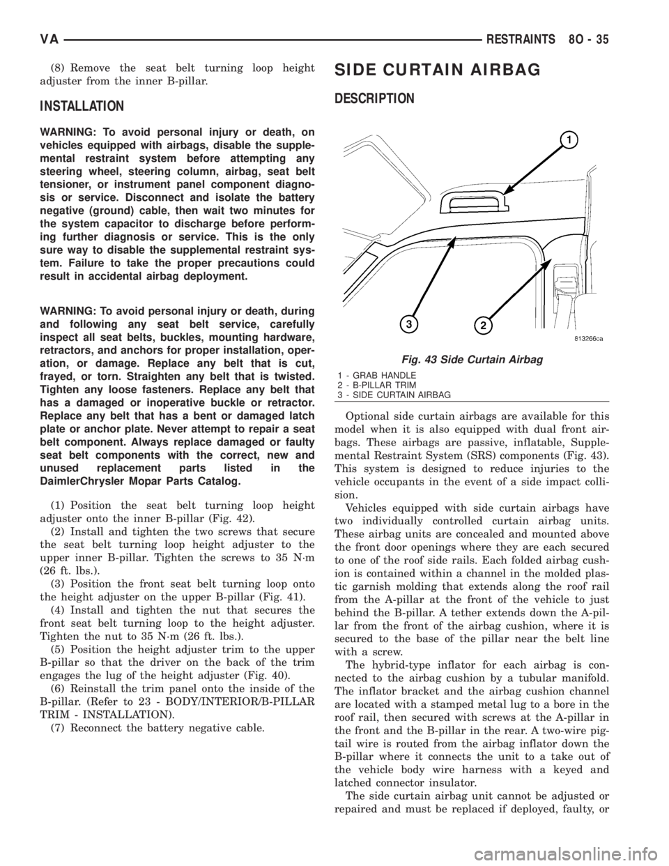
DESCRIPTION
Optional side curtain airbags are available for this
model when it is also equipped with dual front air-
bags. These airbags are passive, inflatable, Supple-
mental Restraint System (SRS) components (Fig. 43).
This system is designed to reduce injuries to the
vehicle occupants in the event of a side impact colli-
sion.
Vehicles equipped with side curtain airbags have
two individually controlled curtain airbag units.
These airbag units are concealed and mounted above
the front door openings where they are each secured
to one of the roof side rails. Each folded airbag cush-
ion is contained within a channel in the molded plas-
tic garnish molding that extends along the roof rail
from the A-pillar at the front of the vehicle to just
behind the B-pillar. A tether extends down the A-pil-
lar from the front of the airbag cushion, where it is
secured to the base of the pillar near the belt line
with a screw.
The hybrid-type inflator for each airbag is con-
nected to the airbag cushion by a tubular manifold.
The inflator bracket and the airbag cushion channel
are located with a stamped metal lug to a bore in the
roof rail, then secured with screws at the A-pillar in
the front and the B-pillar in the rear. A two-wire pig-
tail wire is routed from the airbag inflator down the
B-pillar where it connects the unit to a take out of
the vehicle body wire harness with a keyed and
latched connector insulator.
The side curtain airbag unit cannot be adjusted or
repaired and must be replaced if deployed, faulty, or
Fig. 43 Side Curtain Airbag
1 - GRAB HANDLE
2 - B-PILLAR TRIM
3 - SIDE CURTAIN AIRBAG
VARESTRAINTS 8O - 35
Page 1028 of 2305
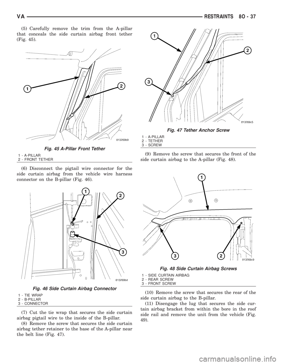
(5) Carefully remove the trim from the A-pillar
that conceals the side curtain airbag front tether
(Fig. 45).
(6) Disconnect the pigtail wire connector for the
side curtain airbag from the vehicle wire harness
connector on the B-pillar (Fig. 46).
(7) Cut the tie wrap that secures the side curtain
airbag pigtail wire to the inside of the B-pillar.
(8) Remove the screw that secures the side curtain
airbag tether retainer to the base of the A-pillar near
the belt line (Fig. 47).(9) Remove the screw that secures the front of the
side curtain airbag to the A-pillar (Fig. 48).
(10) Remove the screw that secures the rear of the
side curtain airbag to the B-pillar.
(11) Disengage the lug that secures the side cur-
tain airbag bracket from within the bore in the roof
side rail and remove the unit from the vehicle (Fig.
49).
Fig. 45 A-Pillar Front Tether
1 - A-PILLAR
2 - FRONT TETHER
Fig. 46 Side Curtain Airbag Connector
1 - TIE WRAP
2 - B-PILLAR
3 - CONNECTOR
Fig. 47 Tether Anchor Screw
1 - A-PILLAR
2 - TETHER
3 - SCREW
Fig. 48 Side Curtain Airbag Screws
1 - SIDE CURTAIN AIRBAG
2 - REAR SCREW
3 - FRONT SCREW
VARESTRAINTS 8O - 37
Page 1029 of 2305
INSTALLATION
The following procedure is for replacement of a
faulty or damaged side curtain airbag. If the airbag
is faulty or damaged, but not deployed, review the
recommended procedures for handling non-deployed
supplemental restraints. (Refer to 8 - ELECTRICAL/
RESTRAINTS - STANDARD PROCEDURE - HAN-
DLING NON-DEPLOYED SUPPLEMENTAL
RESTRAINTS). If the side curtain airbag has been
deployed, review the recommended procedures for
service after a supplemental restraint deployment
before removing the airbag from the vehicle. (Refer to
8 - ELECTRICAL/RESTRAINTS - STANDARD PRO-
CEDURE - SERVICE AFTER A SUPPLEMENTAL
RESTRAINT DEPLOYMENT).
WARNING: To avoid personal injury or death, on
vehicles equipped with airbags, disable the supple-
mental restraint system before attempting any
steering wheel, steering column, airbag, seat belt
tensioner, impact sensor, or instrument panel com-
ponent diagnosis or service. Disconnect and isolate
the battery negative (ground) cable, then wait two
minutes for the system capacitor to discharge
before performing further diagnosis or service. This
is the only sure way to disable the supplemental
restraint system. Failure to take the proper precau-
tions could result in accidental airbag deployment.
WARNING: To avoid personal injury or death, when
removing a deployed airbag, rubber gloves, eye
protection, and a long-sleeved shirt should be
worn. There may be deposits on the airbag unit and
other interior surfaces. In large doses, these depos-
its may cause irritation to the skin and eyes.WARNING: To avoid personal injury or death, use
extreme care to prevent any foreign material from
entering the side curtain airbag, or becoming
entrapped between the side curtain airbag cushion
and the roof rail garnish molding. Failure to
observe this warning could result in occupant inju-
ries upon airbag deployment.
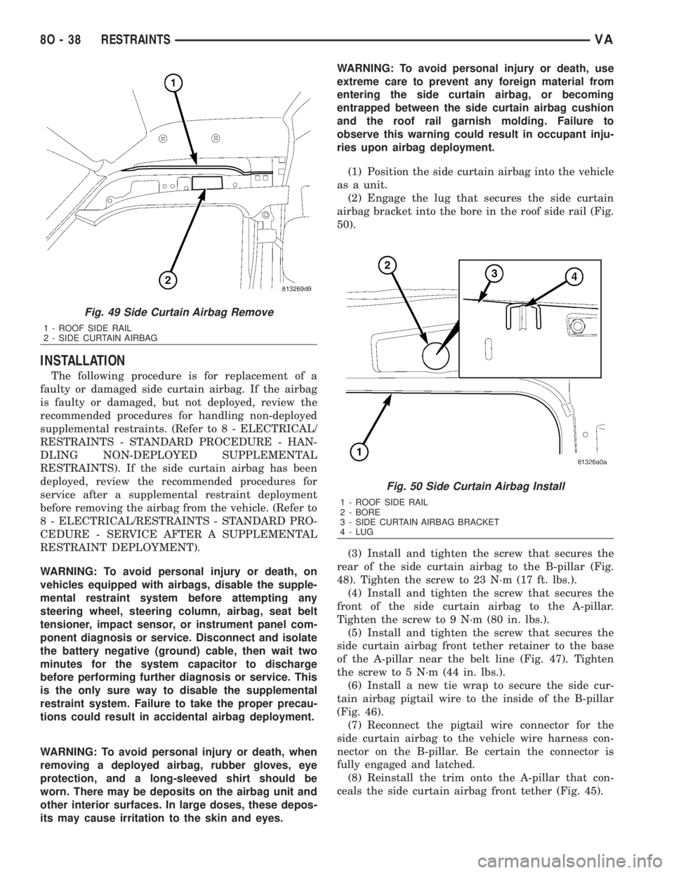
(1) Position the side curtain airbag into the vehicle
as a unit.
(2) Engage the lug that secures the side curtain
airbag bracket into the bore in the roof side rail (Fig.
50).
(3) Install and tighten the screw that secures the
rear of the side curtain airbag to the B-pillar (Fig.
48). Tighten the screw to 23 N´m (17 ft. lbs.).
(4) Install and tighten the screw that secures the
front of the side curtain airbag to the A-pillar.
Tighten the screw to 9 N´m (80 in. lbs.).
(5) Install and tighten the screw that secures the
side curtain airbag front tether retainer to the base
of the A-pillar near the belt line (Fig. 47). Tighten
the screw to 5 N´m (44 in. lbs.).
(6) Install a new tie wrap to secure the side cur-
tain airbag pigtail wire to the inside of the B-pillar
(Fig. 46).
(7) Reconnect the pigtail wire connector for the
side curtain airbag to the vehicle wire harness con-
nector on the B-pillar. Be certain the connector is
fully engaged and latched.
(8) Reinstall the trim onto the A-pillar that con-
ceals the side curtain airbag front tether (Fig. 45).
Fig. 49 Side Curtain Airbag Remove
1 - ROOF SIDE RAIL
2 - SIDE CURTAIN AIRBAG
Fig. 50 Side Curtain Airbag Install
1 - ROOF SIDE RAIL
2 - BORE
3 - SIDE CURTAIN AIRBAG BRACKET
4 - LUG
8O - 38 RESTRAINTSVA
Page 1055 of 2305
RAIN SENSOR
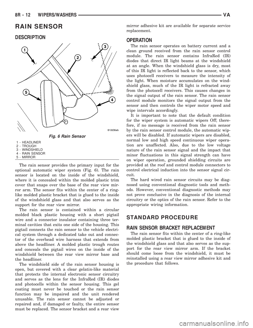
DESCRIPTION
The rain sensor provides the primary input for the
optional automatic wiper system (Fig. 6). The rain
sensor is located on the inside of the windshield,
where it is concealed within the molded plastic trim
cover that snaps over the base of the rear view mir-
ror arm. The sensor fits within the center of a ring-
like molded plastic bracket that is glued to the inside
of the windshield glass and that also serves as the
support for the rear view mirror.
The rain sensor is contained within a circular
molded black plastic housing with a short pigtail
wire and a connector insulator containing three ter-
minal cavities that exits one side of the housing. This
pigtail connects the rain sensor to the vehicle electri-
cal system through a dedicated take out and connec-
tor of the overhead wire harness that extends from
above the headliner. A molded plastic trough routes
and conceals the pigtail wires on the inside of the
windshield between the rear view mirror base and
the headliner.
The windshield side of the rain sensor housing is
open, but covered with a clear gelatin-like material
that protects the internal electronic sensor circuitry
and serves as the lens for the InfraRed (IR) diodes
and photocells within the sensor housing. This gel
coating must never be touched or the rain sensor
function may be impaired and the unit rendered
unusable. The rain sensor cannot be adjusted or
repaired and, if damaged or faulty, the entire sensor
must be replaced. The sensor bracket and a rear viewmirror adhesive kit are available for separate service
replacement.
OPERATION
The rain sensor operates on battery current and a
clean ground received from the rain sensor control
module. The rain sensor contains InfraRed (IR)
diodes that direct IR light beams at the windshield
at an angle. When the windshield glass is dry, most
of this IR light is reflected back to the sensor, which
uses photocell receivers to measure the intensity of
the light. When moisture accumulates on the wind-
shield glass, much of the IR light is refracted away
from the photocell receivers. This causes changes in
the signal output of the rain sensor. The rain sensor
control module monitors the signal output from the
sensor and then controls the wiper motor speed and
wipe intervals accordingly.
It is important to note that the default condition
for the wiper system is automatic wipers Off; there-
fore, if no message is received from the rain sensor
by the rain sensor control module, the automatic wip-
ers will be disabled. If automatic wipers are disabled,
normal low and high speed continuous wiper opera-
tion are unaffected. Also, due to the low voltage
nature of the rain sensor signal and the impact that
minor fluctuations in this signal strength can have
on wiper operation, grounded shielding circuits are
provided at the roof and control module connectors to
control electrical induction into the sensor signal cir-
cuit.
The hard wired rain sensor circuits may be diag-
nosed using conventional diagnostic tools and meth-
ods. However, conventional diagnostic methods may
not prove conclusive in the diagnosis of the internal
circuitry or the optics of the rain sensor. Refer to the
appropriate wiring information.
STANDARD PROCEDURE
RAIN SENSOR BRACKET REPLACEMENT
The rain sensor fits within the center of a ring-like
molded plastic bracket that is glued to the inside of
the windshield glass and that also serves as the sup-
port for the rear view mirror arm. If the bracket
should come loose from the windshield, it must be
reinstalled using a rear view mirror adhesive kit and
the procedure that follows.
Fig. 6 Rain Sensor
1 - HEADLINER
2 - TROUGH
3 - WINDSHIELD
4 - RAIN SENSOR
5 - MIRROR
8R - 12 WIPERS/WASHERSVA
Page 1057 of 2305
(8) Reconnect the battery negative cable.
REMOVAL
WARNING: To avoid personal injury or death, on
vehicles equipped with airbags, disable the supple-
mental restraint system before attempting any
steering wheel, steering column, airbag, seat belt
tensioner, or instrument panel component diagno-
sis or service. Disconnect and isolate the battery
negative (ground) cable, then wait two minutes for
the system capacitor to discharge before perform-
ing further diagnosis or service. This is the only
sure way to disable the supplemental restraint sys-
tem. Failure to take the proper precautions could
result in accidental airbag deployment.
(1) Disconnect and isolate the battery negative
cable.
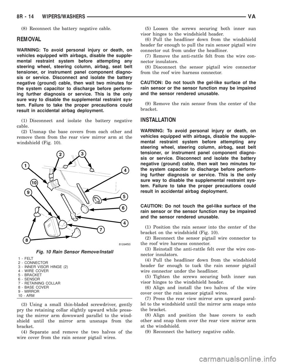
(2) Unsnap the base covers from each other and
remove them from the rear view mirror arm at the
windshield (Fig. 10).
(3) Using a small thin-bladed screwdriver, gently
pry the retaining collar slightly upward while press-
ing the mirror arm downward parallel to the wind-
shield until the mirror arm unsnaps from the
bracket.
(4) Separate and remove the two halves of the
wire cover from the rain sensor pigtail wires.(5) Loosen the screws securing both inner sun
visor hinges to the windshield header.
(6) Pull the headliner down from the windshield
header far enough to pull the rain sensor pigtail wire
connector out from under the headliner.
(7) Remove the anti-rattle felt from the wire con-
nector insulators.
(8) Disconnect the sensor pigtail wire connector
from the roof wire harness connector.
CAUTION: Do not touch the gel-like surface of the
rain sensor or the sensor function may be impaired
and the sensor rendered unusable.
(9) Remove the rain sensor from the center of the
bracket.
INSTALLATION
WARNING: To avoid personal injury or death, on
vehicles equipped with airbags, disable the supple-
mental restraint system before attempting any
steering wheel, steering column, airbag, seat belt
tensioner, or instrument panel component diagno-
sis or service. Disconnect and isolate the battery
negative (ground) cable, then wait two minutes for
the system capacitor to discharge before perform-
ing further diagnosis or service. This is the only
sure way to disable the supplemental restraint sys-
tem. Failure to take the proper precautions could
result in accidental airbag deployment.
CAUTION: Do not touch the gel-like surface of the
rain sensor or the sensor function may be impaired
and the sensor rendered unusable.
(1) Position the rain sensor into the center of the
bracket on the windshield (Fig. 10).
(2) Reconnect the sensor pigtail wire connector to
the roof wire harness connector.
(3) Reinstall the anti-rattle felt over the wire con-
nector insulators.
(4) Pull the headliner down from the windshield
header far enough to tuck the rain sensor pigtail
wire connector under the headliner.
(5) Tighten the screws securing both inner sun
visor hinges to the windshield header.
(6) Align and install the two halves of the wire
cover over the rain sensor pigtail wires.
(7) Press the rear view mirror arm upward paral-
lel to the windshield until the mirror arm snaps onto
the bracket.
(8) Align and position the base covers to each
other and snap them over the rear view mirror arm
at the windshield.
(9) Reconnect the battery negative cable.
Fig. 10 Rain Sensor Remove/Install
1 - FELT
2 - CONNECTOR
3 - INNER VISOR HINGE (2)
4 - WIRE COVER
5 - BRACKET
6 - SENSOR
7 - RETAINING COLLAR
8 - BASE COVER
9 - MIRROR
10 - ARM
8R - 14 WIPERS/WASHERSVA
Page 1987 of 2305
(14) Install the door. (Refer to 23 - BODY/DOORS
- SLIDING/SLIDING DOOR - INSTALLATION)
INSTALLATION
(1) Install the door by inserting the center and
upper rollers into the tracks and sliding the door for-
ward to the front of each track.
(2) Connect the lower roller arm and install the
screws.
(3) Tighten the screws to 25 N´m (18 ft. lbs.).
(4) Install door stop and screws.
(5) Tighten the screws to 10 N´m (89 in. lbs.).
(6) Install the center track end piece and install
the screw.
(7) Tighten the screw to 10 N´m (89 in. lbs.).
(8) Check and adjust door if necessary. (Refer to 23
- BODY/DOORS - SLIDING/SLIDING DOOR -
ADJUSTMENTS)
(9) Connect battery negative cable.
ADJUSTMENTS
ADJUSTMENT
NOTE: Door adjustment measurements should be
taken from stationary or welded body panels like
the roof, rocker or quarter panels.
A suitable body sealant should be used when
removing or moving the hinges.
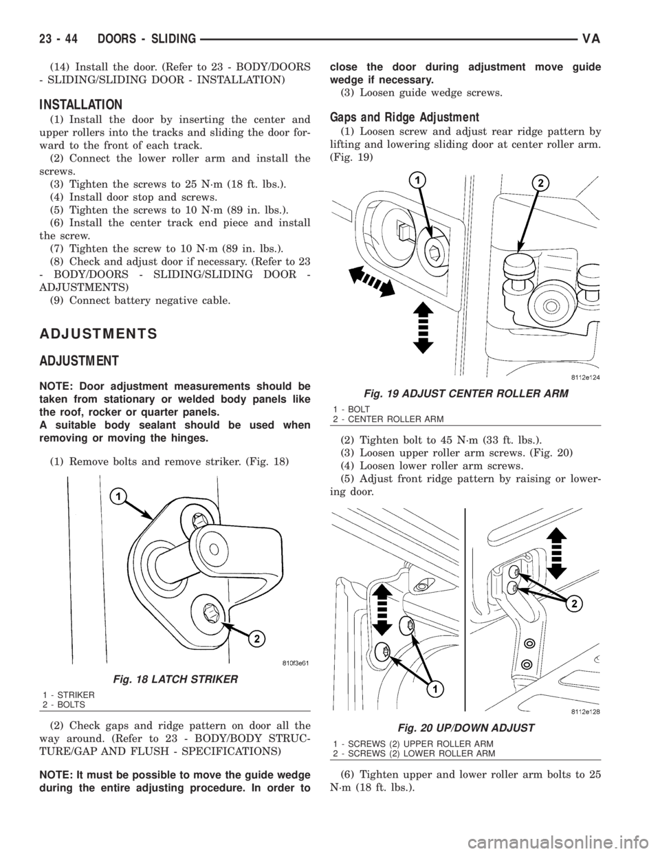
(1) Remove bolts and remove striker. (Fig. 18)
(2) Check gaps and ridge pattern on door all the
way around. (Refer to 23 - BODY/BODY STRUC-
TURE/GAP AND FLUSH - SPECIFICATIONS)
NOTE: It must be possible to move the guide wedge
during the entire adjusting procedure. In order toclose the door during adjustment move guide
wedge if necessary.
(3) Loosen guide wedge screws.
Gaps and Ridge Adjustment
(1) Loosen screw and adjust rear ridge pattern by
lifting and lowering sliding door at center roller arm.
(Fig. 19)
(2) Tighten bolt to 45 N´m (33 ft. lbs.).
(3) Loosen upper roller arm screws. (Fig. 20)
(4) Loosen lower roller arm screws.
(5) Adjust front ridge pattern by raising or lower-
ing door.
(6) Tighten upper and lower roller arm bolts to 25
N´m (18 ft. lbs.).
Fig. 18 LATCH STRIKER
1 - STRIKER
2 - BOLTS
Fig. 19 ADJUST CENTER ROLLER ARM
1 - BOLT
2 - CENTER ROLLER ARM
Fig. 20 UP/DOWN ADJUST
1 - SCREWS (2) UPPER ROLLER ARM
2 - SCREWS (2) LOWER ROLLER ARM
23 - 44 DOORS - SLIDINGVA