2006 MERCEDES-BENZ SPRINTER horn
[x] Cancel search: hornPage 12 of 2305

TABLE OF CONTENTS - Continued
FUSES (FUSE BLOCK NO. 2)............................................274
FUSES (FUSE BLOCK NO. 3)............................................276
FUSES (FUSE/RELAY BLOCK)...........................................278
HOOD AJAR SWITCH - BLACK...........................................278
HORN (VTSS).........................................................278
IGNITION LOCK SWITCH - BLACK........................................278
INSTRUMENT CLUSTER C1.............................................279
INSTRUMENT CLUSTER C2 - WHITE.....................................279
INTRUSION SENSOR NO. 1 - BLACK.....................................279
INTRUSION SENSOR NO. 2 - BLACK.....................................279
INTRUSION SENSOR NO. 3 - BLACK.....................................280
MASTER DOOR LOCK SWITCH..........................................280
PANIC ALARM SWITCH - BLACK.........................................280
FUSES (PDC).........................................................281
RADIO C1 - BLACK....................................................282
RADIO C2............................................................282
RECIRCULATED AIR SOLENOID VALVE...................................282
REFRIGERANT PRESSURE SENSOR.....................................282
A/C AUXILIARY FAN RELAY (RELAY BLOCK)...............................284
CIRCULATION PUMP RELAY-CABIN HEATER MODULE (RELAY BLOCK).......284
D+ RELAY NO. 2 (RELAY BLOCK)........................................284
FAN STAGE 1 RELAY (RELAY BLOCK)....................................284
OPTIONAL EQUIPMENT RELAY (RELAY BLOCK)...........................284
REMOTE KEYLESS ENTRY ANTENNA....................................284
SEAT BELT SWITCH...................................................284
SEAT BELT TENSIONER-DRIVER - YELLOW...............................285
SEAT BELT TENSIONER-PASSENGER - YELLOW...........................285
SECURITY SYSTEM MODULE C1 - BROWN...............................285
SECURITY SYSTEM MODULE C2 - LT. GREEN.............................286
SENTRY KEY REMOTE ENTRY MODULE (SKREEM)........................286
SHIFTER ASSEMBLY - BLACK...........................................286
SIREN - BLACK.......................................................286
STEERING ANGLE SENSOR............................................287
TOWING/INTRUSION SENSOR ON/OFF SWITCH...........................287
TRANSMISSION CONTROL MODULE C1 - BLACK..........................287
TRANSMISSION CONTROL MODULE C2 - BLACK..........................288
WATER CYCLE VALVE..................................................288
WINDOW DEFOGGER-LEFT REAR.......................................288
WINDOW DEFOGGER-RIGHT REAR......................................288
10.0 SCHEMATIC DIAGRAMS................................................289
10.1AIRBAG SYSTEM.................................................289
10.2COMMUNICATION................................................290
10.2.1COMMUNICATION K-LINES................................290
10.2.2CAN BUS NETWORK......................................291
10.3HEATING & A/C...................................................292
10.3.1AUTOMATIC TEMPERATURE CONTROL (ATC)................292
10.3.2CABIN HEATER MODULE (CHM)............................293
10.3.3HEATER BOOSTER MODULE (HBM).........................294
10.4INSTRUMENT CLUSTER...........................................295
vii
Page 16 of 2305
When supplied with the proper electrical signal, the
inflator discharged the gas directly into the cush-
ion. The airbag cannot be repaired, and must be
replaced if deployed or in any way damaged.
WARNING: THE DRIVER AIRBAG MODULE
CONTAINS ARGON GAS PRESSURIZED TO
OVER 17236.89 Kpa (2500 PSI). DO NOT
ATTEMPT TO DISMANTLE AN AIRBAG
MODULE OR TAMPER WITH ITS INFLATOR.
DO NOT PUNCTURE, INCINERATE, OR
BRING INTO CONTACT WITH ELECTRICITY.
DO NOT STORE AT TEMPERATURE
EXCEEDING 93ÉC (200ÉF). REPLACE AIRBAG
SYSTEM COMPONENTS ONLY WITH PARTS
SPECIFIED IN THE CHRYSLER MOPAR
PARTS CATALOG. SUBSTITUTE PARTS MAY
APPEAR INTER-CHANGEABLE, BUT
INTERNAL DIFFERENCES MAY RESULT IN
INFERIOR OCCUPANT PROTECTION. THE
FASTENERS, SCREWS, AND BOLTS
ORIGINALLY USED FOR THE AIRBAG
SYSTEM COMPONENTS HAVE SPECIAL
COATINGS AND ARE SPECIFICALLY
DESIGNED FOR THE AIRBAG SYSTEM. THEY
MUST NEVER BE REPLACED WITH ANY
SUBSTITUTES. ANY TIME A NEW FASTENER
IS NEEDED, REPLACE IT WITH THE
CORRECT FASTENERS PROVIDED IN THE
SERVICE PACKAGE OR SPECIFIED IN THE
MOPAR PARTS CATALOG. FAILURE TO
TAKE THE PROPER PRECAUTIONS COULD
RESULT IN ACCIDENTAL AIRBAG
DEPLOYMENT AND PERSONAL INJURY OR
DEATH.
3.1.2 CLOCKSPRING
The clockspring is mounted on the steering col-
umn under the steering wheel. This assembly con-
sists of a plastic housing which contains a flat,
ribbon-like, electrically conductive tape that winds
and unwinds with the steering wheel rotation. The
clockspring is used to maintain a continuous elec-
trical circuit between the instrument panel wiring
and the driver airbag and the horn. The clockspring
must be properly centered when it is reinstalled on
the steering column following any service proce-
dure, or it could be damaged. The clockspring can-
not be repaired and it must be replaced.
3.1.3 PASSENGER AIRBAG
The Passenger Airbag is optional equipment.
When supplied with the proper electrical signal the
passenger airbag inflator discharges the gas di-rectly into the cushion. The airbag module cannot
be repaired, and must be replaced if deployed or in
any way damaged.
WARNING: THE PASSENGER AIRBAG
MODULE CONTAINS ARGON GAS
PRESSURIZED TO 17236.89 Kpa (2500 PSI).
DO NOT ATTEMPT TO DISMANTLE AN
AIRBAG MODULE OR TAMPER WITH ITS
INFLATOR. DO NOT PUNCTURE,
INCINERATE, OR BRING INTO CONTACT
WITH ELECTRICITY. DO NOT STORE AT
TEMPERATURE EXCEEDING 93ÉC (200ÉF).
REPLACE AIRBAG SYSTEM COMPONENTS
ONLY WITH PARTS SPECIFIED IN THE
MOPAR PARTS CATALOG. SUBSTITUTE
PARTS MAY APPEAR INTER-CHANGEABLE,
BUT INTERNAL DIFFERENCES MAY RESULT
IN INFERIOR OCCUPANT PROTECTION. THE
FASTENERS, SCREWS, AND BOLTS
ORIGINALLY USED FOR THE AIRBAG
SYSTEM COMPONENTS HAVE SPECIAL
COATINGS AND ARE SPECIFICALLY
DESIGNED FOR THE AIRBAG SYSTEM. THEY
MUST NEVER BE REPLACED WITH ANY
SUBSTITUTES. ANY TIME A NEW FASTENER
IS NEEDED, REPLACE IT WITH THE
CORRECT FASTENERS PROVIDED IN THE
SERVICE PACKAGE OR SPECIFIED IN THE
MOPAR PARTS CATALOG. FAILURE TO
TAKE THE PROPER PRECAUTIONS COULD
RESULT IN ACCIDENTAL AIRBAG
DEPLOYMENT AND PERSONAL INJURY OR
DEATH.
3.1.4 SEAT BELT TENSIONERS
Front seat belt systems incorporate a Driver and
optional Passenger Seat Belt Tensioner Retractors.
At the onset of an impact event each tensioner uses
a pyrotechnic device, which is triggered simulta-
neously with the front airbags, to rapidly retract
the seat belts. With the slack removed, the occu-
pant's forward motion in an impact will be reduced
as will the likelihood of contacting interior compo-
nents. After an impact that deploys the airbag, the
seat belt tensioner assembly must be replaced. The
ACM module monitors the Seat Belt Tensioners
circuit resistance and reports active and stored
DTCs if any problem is found. Follow all of the
safety procedures when servicing tensioner.
3.1.5 SPECIAL TOOLS
Airbag load tools 8310 and 8443 are used in some
airbag diagnostic test. The load tools contain fixed
resistive loads, jumpers and adapters. The fixed
3
GENERAL INFORMATION
Page 291 of 2305
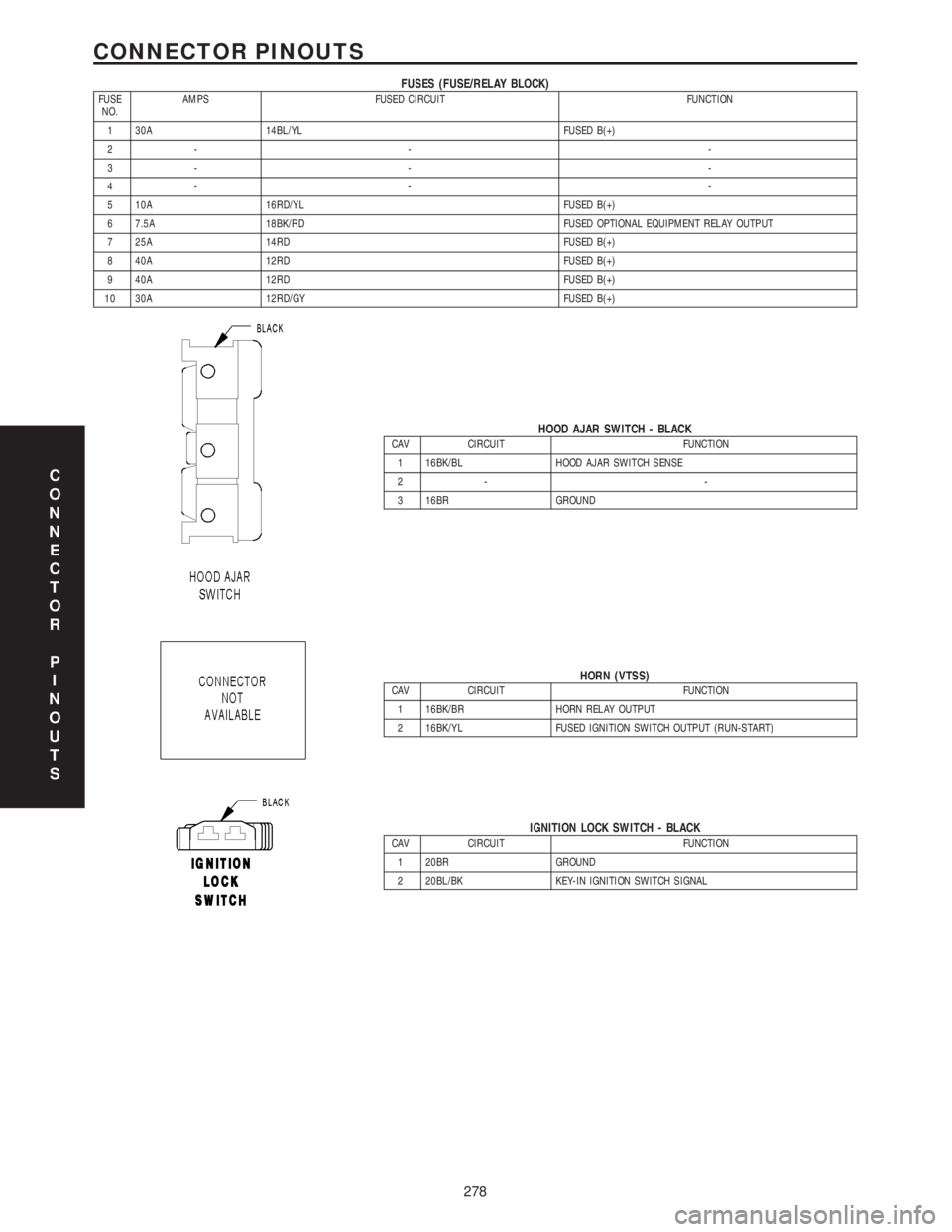
FUSES (FUSE/RELAY BLOCK)FUSE
NO.AMPS FUSED CIRCUIT FUNCTION
1 30A 14BL/YL FUSED B(+)
2- - -
3- - -
4- - -
5 10A 16RD/YL FUSED B(+)
6 7.5A 18BK/RD FUSED OPTIONAL EQUIPMENT RELAY OUTPUT
7 25A 14RD FUSED B(+)
8 40A 12RD FUSED B(+)
9 40A 12RD FUSED B(+)
10 30A 12RD/GY FUSED B(+)
HOOD AJAR SWITCH - BLACKCAV CIRCUIT FUNCTION
1 16BK/BL HOOD AJAR SWITCH SENSE
2- -
3 16BR GROUND
HORN (VTSS)CAV CIRCUIT FUNCTION
1 16BK/BR HORN RELAY OUTPUT
2 16BK/YL FUSED IGNITION SWITCH OUTPUT (RUN-START)
IGNITION LOCK SWITCH - BLACKCAV CIRCUIT FUNCTION
1 20BR GROUND
2 20BL/BK KEY-IN IGNITION SWITCH SIGNAL
C
O
N
N
E
C
T
O
R
P
I
N
O
U
T
S
278
CONNECTOR PINOUTS
Page 704 of 2305
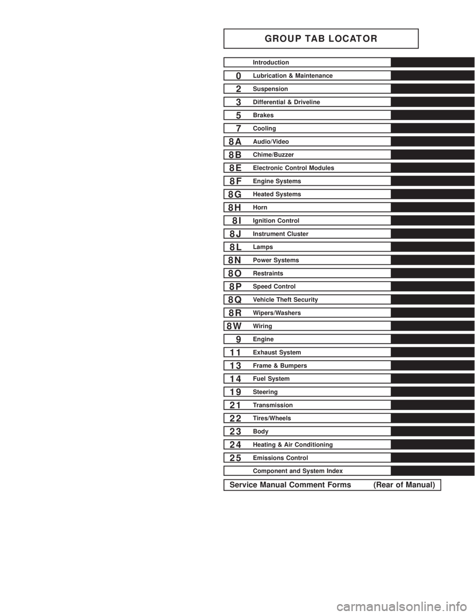
GROUP TAB LOCATOR
Introduction
0Lubrication & Maintenance
2Suspension
3Differential & Driveline
5Brakes
7Cooling
8AAudio/Video
8BChime/Buzzer
8EElectronic Control Modules
8FEngine Systems
8GHeated Systems
8HHorn
8IIgnition Control
8JInstrument Cluster
8LLamps
8NPower Systems
8ORestraints
8PSpeed Control
8QVehicle Theft Security
8RWipers/Washers
8WWiring
9Engine
11Exhaust System
13Frame & Bumpers
14Fuel System
19Steering
21Transmission
22Tires/Wheels
23Body
24Heating & Air Conditioning
25Emissions Control
Component and System Index
Service Manual Comment Forms (Rear of Manual)
Page 708 of 2305
FASTENER IDENTIFICATION
DESCRIPTION
The SAE bolt strength grades range from grade 2
to grade 8. The higher the grade number, the greater
the bolt strength. Identification is determined by the
line marks on the top of each bolt head. The actual
bolt strength grade corresponds to the number of line
marks plus 2. The most commonly used metric bolt
strength classes are 9.8 and 10.9. The metric
strength class identification number is imprinted on
the head of the bolt. The higher the class number,
the greater the bolt strength. Some metric nuts are
imprinted with a single-digit strength class on the
nut face. Refer to the Fastener Identification and
Fastener Strength Charts (Fig. 2) and (Fig. 3).
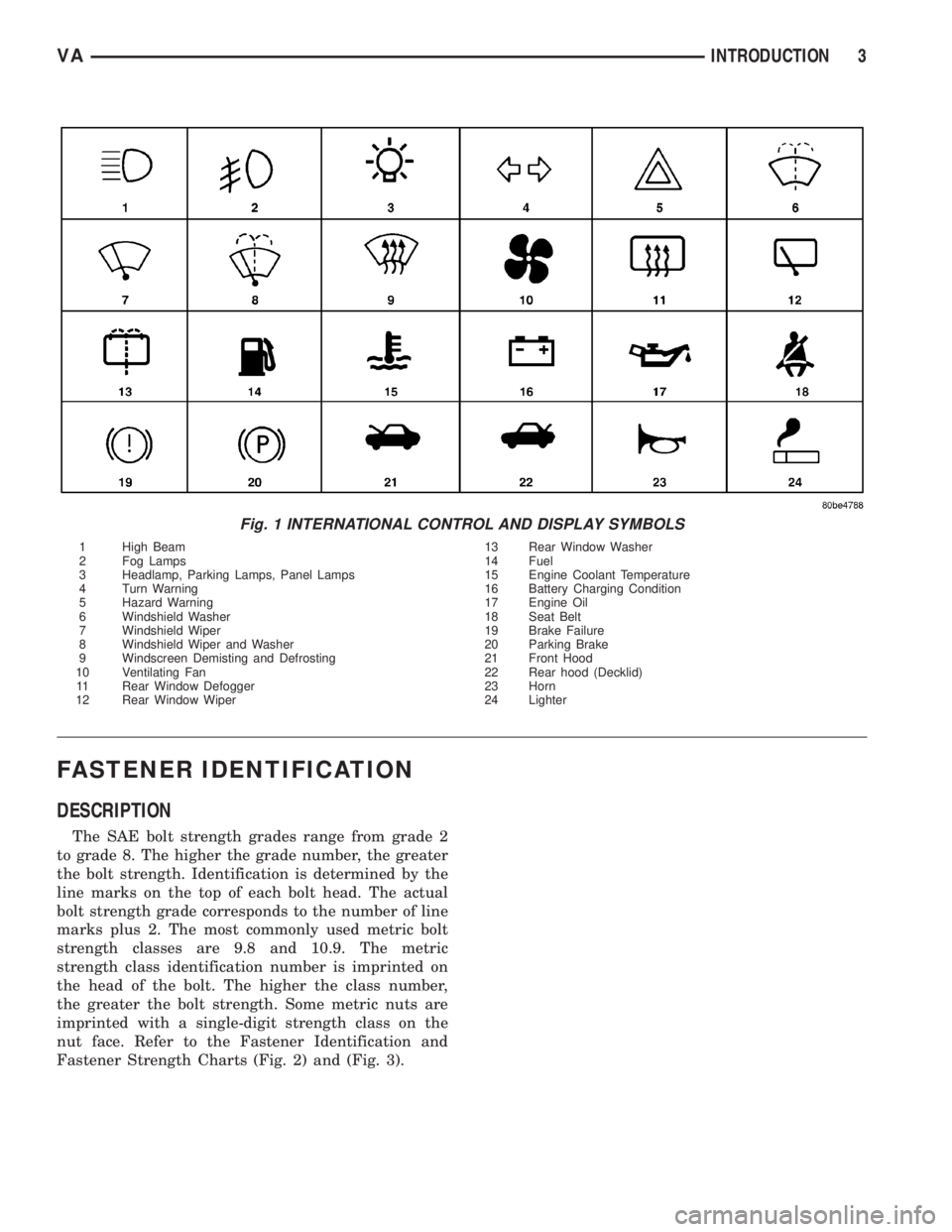
Fig. 1 INTERNATIONAL CONTROL AND DISPLAY SYMBOLS
1 High Beam 13 Rear Window Washer
2 Fog Lamps 14 Fuel
3 Headlamp, Parking Lamps, Panel Lamps 15 Engine Coolant Temperature
4 Turn Warning 16 Battery Charging Condition
5 Hazard Warning 17 Engine Oil
6 Windshield Washer 18 Seat Belt
7 Windshield Wiper 19 Brake Failure
8 Windshield Wiper and Washer 20 Parking Brake
9 Windscreen Demisting and Defrosting 21 Front Hood
10 Ventilating Fan 22 Rear hood (Decklid)
11 Rear Window Defogger 23 Horn
12 Rear Window Wiper 24 Lighter
VAINTRODUCTION 3
Page 856 of 2305

ELECTRONIC CONTROL MODULES
TABLE OF CONTENTS
page page
CENTRAL TIMER MODULE
DESCRIPTION..........................1
OPERATION............................1
DIAGNOSIS AND TESTING - CENTRAL TIMER
MODULE.............................2
REMOVAL.............................2
INSTALLATION..........................3
CONTROLLER ANTILOCK BRAKE
DESCRIPTION..........................3
REMOVAL.............................3INSTALLATION..........................3
ENGINE CONTROL MODULE
DESCRIPTION..........................3
REMOVAL.............................6
INSTALLATION..........................6
TRANSMISSION CONTROL MODULE
DESCRIPTION..........................6
OPERATION............................7
STANDARD PROCEDURE - TCM ADAPTATION . 10
CENTRAL TIMER MODULE
DESCRIPTION
The central timer module (CTM) is located beneath
the driver seat. The CTM uses information carried on
the programmable communications interface (PCI)
data bus network along with many hard wired inputs
to monitor many sensor and switch inputs. In
response to those inputs, the circuitry and program-
ming of the CTM allow it to supply the vehicle occu-
pants with audible and visual information, and to
control and integrate many functions and features of
the vehicle through both hard wired outputs and the
transmission of message outputs to other modules in
the vehicle over the PCI data bus.
The features that the CTM supports or controls
include the following:
²Central Locking- The CTM on vehicles
equipped with the optional Vehicle Theft Security
System (VTSS) includes a central locking/unlocking
feature.
²Enhanced Accident Response- The CTM pro-
vides an optional enhanced accident response fea-
ture. This is a programmable feature.
²Panic Mode- The CTM provides support for
the optional RKE system panic mode including horn,
headlamp, and park lamp flash features.
²Power Lock Control- The CTM provides the
optional power lock system features, including sup-
port for the automatic door lock and door lock inhibit
modes.
²Programmable Features- The CTM provides
support for certain programmable features.
²Remote Keyless Entry- The CTM provides
the optional Remote Keyless Entry (RKE) system fea-
tures, including support for the RKE Lock (with
optional horn and park lamps flash), Unlock (with
park lamps flash, driver-door-only unlock, andunlock-all-doors), Panic, and illuminated entry
modes, as well as the ability to be programmed to
recognize up to four RKE transmitters. The RKE
horn, driver-door-only unlock, and unlock-all-doors
features are programmable.
²Vehicle Theft Security System- The CTM
provides control of the optional Vehicle Theft Secu-
rity System (VTSS) features, including support for
the central locking/unlocking mode and control of the
Security indicator in the instrument cluster.
Hard wired circuitry connects the CTM to the elec-
trical system of the vehicle. Refer to the appropriate
wiring information.
Many of the features in the vehicle controlled or
supported by the CTM are programmable using the
DRBIIItscan tool. However, if any of the CTM hard-
ware components are damaged or faulty, the entire
CTM unit must be replaced. The hard wired inputs
or outputs of all CTM versions can be diagnosed
using conventional diagnostic tools and methods;
however, for diagnosis of the CTM or the PCI data
bus, the use of a DRBIIItscan tool is required. Refer
to the appropriate diagnostic information.
OPERATION
The central timer module (CTM) monitors many
hard wired switch and sensor inputs as well as those
resources it shares with other modules in the vehicle
through its communication over the programmable
communications interface (PCI) data bus network.
The internal programming and all of these inputs
allow the CTM to determine the tasks it needs to
perform and their priorities, as well as both the stan-
dard and optional features that it should provide.
The CTM then performs those tasks and provides
those features through both PCI data bus communi-
cation with other modules and hard wired outputs
through a number of driver circuits, relays, and
VAELECTRONIC CONTROL MODULES 8E - 1
Page 916 of 2305
HORN
TABLE OF CONTENTS
page page
HORN
REMOVAL.............................1
INSTALLATION..........................1HORN SWITCH
REMOVAL.............................1
INSTALLATION..........................1
HORN
REMOVAL
(1) Disconnect and isolate the battery negative
cable.
(2) Disconnect the wire harness connectors.
(3) Remove the mounting fastener and horns.
INSTALLATION
(1) Position horns and install mounting fasteners.
(2) Connect wire harness connector.
(3) Connect battery negative cable.
HORN SWITCH
REMOVAL
(1) Disconnect and isolate the battery negative
cable.
(2) Remove the drivers side airbag (Refer to 8 -
ELECTRICAL/RESTRAINTS/DRIVER AIRBAG -
REMOVAL).
(3) Remove the electrical harness connector.
(4) Remove the mounting fasteners and horn
switch.
INSTALLATION
(1) Connect the wire harness connector.
(2) Position the horn switch and install the mount-
ing fasteners.
(3) Install the drivers side airbag (Refer to 8 -
ELECTRICAL/RESTRAINTS/DRIVER AIRBAG -
INSTALLATION).
(4) Connect the battery negative cable.
VAHORN 8H - 1
Page 953 of 2305
seat riser, a fog lamp switch installed in the cluster
bezel on the instrument panel outboard of the steer-
ing column, and a fog lamp bulb installed in each of
the two front lamp units. The front fog lamps have a
path to ground at all times through their connection
to the vehicle wire harness. The headlamp switch cir-
cuitry of the left (lighting) control stalk of the multi-
function switch controls front fog lamp operation by
providing battery current to the front fog lamp relay
only when the low beam headlamps are selected. The
fog lamp switch controls front fog lamp operation by
energizing or de-energizing the front fog lamp relay
control coil.
HAZARD WARNING LAMPS
With the hazard switch in the On position, the
hazard switch button illuminates and the right and
left turn signal indicators as well as the right and
left turn signal lamps begin to flash on and off. When
the hazard warning system is activated, the hazard
switch circuitry within the multi-function switch and
the wipers, turn signals and engine start control
module electronic circuitry within the fuse block will
repeatedly energize and de-energize the turn signal
relay located in the fuse block. The turn signal relay
switches battery current from a fused B(+) fuse in
the fuse block to the turn signal indicators and the
turn signal lamps. The flashing of the hazard switch
button illumination lamp is also controlled by the
output from the turn signal relay.
HEADLAMPS
The headlamp system includes the exterior lighting
switches integral to the left (lighting) control stalk of
the multi-function switch as well as the low and high
beam bulbs installed in the right and left front lamp
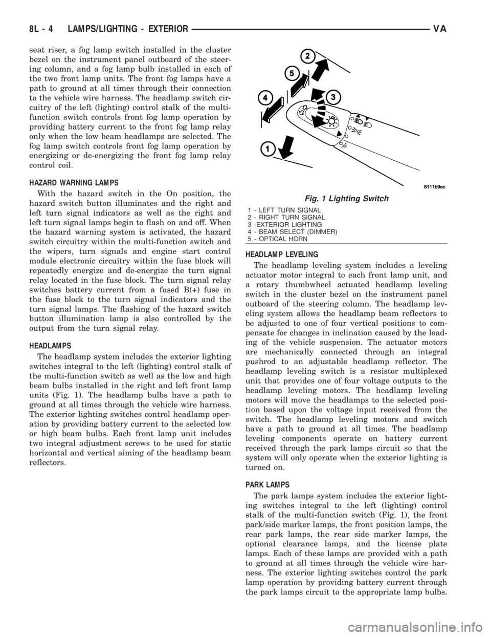
units (Fig. 1). The headlamp bulbs have a path to
ground at all times through the vehicle wire harness.
The exterior lighting switches control headlamp oper-
ation by providing battery current to the selected low
or high beam bulbs. Each front lamp unit includes
two integral adjustment screws to be used for static
horizontal and vertical aiming of the headlamp beam
reflectors.HEADLAMP LEVELING
The headlamp leveling system includes a leveling
actuator motor integral to each front lamp unit, and
a rotary thumbwheel actuated headlamp leveling
switch in the cluster bezel on the instrument panel
outboard of the steering column. The headlamp lev-
eling system allows the headlamp beam reflectors to
be adjusted to one of four vertical positions to com-
pensate for changes in inclination caused by the load-
ing of the vehicle suspension. The actuator motors
are mechanically connected through an integral
pushrod to an adjustable headlamp reflector. The
headlamp leveling switch is a resistor multiplexed
unit that provides one of four voltage outputs to the
headlamp leveling motors. The headlamp leveling
motors will move the headlamps to the selected posi-
tion based upon the voltage input received from the
switch. The headlamp leveling motors and switch
have a path to ground at all times. The headlamp
leveling components operate on battery current
received through the park lamps circuit so that the
system will only operate when the exterior lighting is
turned on.
PARK LAMPS
The park lamps system includes the exterior light-
ing switches integral to the left (lighting) control
stalk of the multi-function switch (Fig. 1), the front
park/side marker lamps, the front position lamps, the
rear park lamps, the rear side marker lamps, the
optional clearance lamps, and the license plate
lamps. Each of these lamps are provided with a path
to ground at all times through the vehicle wire har-
ness. The exterior lighting switches control the park
lamp operation by providing battery current through
the park lamps circuit to the appropriate lamp bulbs.
Fig. 1 Lighting Switch
1 - LEFT TURN SIGNAL
2 - RIGHT TURN SIGNAL
3 -EXTERIOR LIGHTING
4 - BEAM SELECT (DIMMER)
5 - OPTICAL HORN
8L - 4 LAMPS/LIGHTING - EXTERIORVA