2006 MERCEDES-BENZ SPRINTER air conditioning
[x] Cancel search: air conditioningPage 19 of 2305

1. Connect the DRBIIItto the DLC.
2. Place the shift lever in park.
3. Start the engine.
4. Set the blower to high speed.
5. Set the temperature selector to full cold.
6. Press air conditioning switch on.
7. With the DRBIIItin Sensors, verify that the:
A. ambient temperature is above 59F (15C).
B. refrigerant pressure is between 29 and 348
PSI (2 and 24 bar).
C. evaporator temperature is above 36.5F
(2.5C).
D. coolant temperature is above 158F (70C).
When all of the prerequisites have been met, use
the DRBIIItto record and erase all stored ATC
DTCs, and then select System Tests, and run the
ATC Function Test. When complete, check to see if
any active DTCs are present. If so, refer to the
symptom list in the Heating & A/C category for the
diagnostic procedure(s). If there are no DTCs
present, yet the performance seems less than ideal,
use the DRBIIItto look at all sensor values and the
status of the various inputs and outputs to see if
there is a deficiency detected that has not fully shut
down the system. For additional information, refer
to Sensor Values and Input/Output Status under
Diagnostic Tips in this section and to Section 11.0
for evaporator temperature sensor and air outlet
temperature sensor resistance to temperature spec-
ifications charts. Also, confirm that the water cycle
valve is functioning. Remember that the valve is
normally open. The pulse width signal will offer
insight into the valve's operation. The lower the
percentage number, the more open the valve be-
comes. Confirm that the valve is responding to the
signal from the ATC. If functioning correctly, verify
mode and blend door operation. If okay, the diagno-
sis then becomes purely refrigerant system related.
Attach the appropriate gauges and diagnose the
refrigeration system. Refer to the Service Informa-
tion for refrigerant system diagnostic procedures.
DIAGNOSTIC TIPS
SENSOR VALUES
Ambient Air Temperature
The Instrument Cluster transmits Ambient Air
Temperature Sensor data. In the event of a CAN
Bus communication failure, the last stored value is
displayed as a substitute value.
Interior Temperature
The normal range for the Interior Temperature
Sensor is from 32ÉF to 104ÉF. An implausible tem-
perature value indicates that the Interior Temper-
ature Sensor is bad. The repair in this case would be
to replace the ATC Module since the sensor is
integral to the module.Evaporator Temperature
The normal range for the Evaporator Temperature
Sensor is from 14ÉF to 104ÉF. A substitute value of
14ÉF with no updates indicates an Evaporator Tem-
perature Sensor circuit failure.
Air Outlet Temperature
The normal range for the Air Outlet Temperature
Sensor is from 32ÉF to 203ÉF. A substitute value of
111.1ÉF indicates an Air Outlet Temperature Sensor
circuit failure.
Coolant Temperature
The Engine Control Module transmits Coolant
Temperature Sensor date. In the event of a CAN
Bus communication failure, 257ÉF is displayed as a
substitute value.
Interior Temperature Controller
The normal range for the Blend control is from 62ÉF
to 144ÉF. This value represents the temperature set
by the operator. An implausible temperature value
or a temperature value that fails to change when
rotating the Blend control indicates that the Blend
control is bad. The repair in this case would be to
replace the ATC Module since the Blend control
integral to the module.
Refrigerant Pressure
The normal range for the Refrigerant Pressure
Sensor is from 29 PSI to 406 PSI. A substitute value
of 413 PSI indicates a Refrigerant Pressure Sensor
circuit failure. In addition, the normal range for
Pressure Sensor voltage is 0 volts to 5 volts. A value
of 0.9 volts indicates an open voltage supply circuit,
while a value of -999 indicates an open in all three
sensor circuits.
Water Cycle Valve
The normal range of the Water Cycle Valve is from
0% to 100%. The value indicates the extent to which
the valve is closed. A value of 100% indicates that
the valve is fully closed.
Intense Inst Light
The Instrument Cluster transmits this data. The
normal range for lighting intensity is from 0% to
100%. The value indicates the extent to which the
illumination has dimmed. A value of 0% indicates
bright while a value >0% indicates dimming. In the
event of a CAN Bus communication failure, 0% is
displayed as a substitute value.
INPUT/OUTPUT STATUS
Compressor Clutch
The ATC Module transmits this data. A status of
9ON9indicates that the compressor is operational. A
status of9OFF9indicates the compressor is not
operational.
6
GENERAL INFORMATION
Page 26 of 2305

WARNING:REASSEMBLE ALL COMPONENTS
BEFORE ROAD TESTING A VEHICLE. DO NOT
TRY TO READ THE DRBIIITSCREEN OR
OTHER TEST EQUIPMENT DURING A TEST
DRIVE. DO NOT HANG THE DRBIIITOR OTHER
TEST EQUIPMENT FROM THE REARVIEW
MIRROR DURING A TEST DRIVE. HAVE AN
ASSISTANT AVAILABLE TO OPERATE THE
DRBIIITOR OTHER TEST EQUIPMENT.
FAILURE TO FOLLOW THESE INSTRUCTIONS
CAN RESULT IN PERSONAL INJURY OR
DEATH.
5.0 REQUIRED TOOLS AND
EQUIPMENT
DRBIIIt(diagnostic read-out box)
Jumper wires
Ohmmeter
Voltmeter
Test Light
8310 Airbag System Load Tool
8443 SRS Airbag System Load Tool
9001 R F Detector
6.0 GLOSSARY OF TERMS
ABSantilock brake system
ACMairbag control module
ACTactuator
AECMairbag electronic control module
(ACM)
ASDMairbag system diagnostic module
(ACM)
AT Cautomatic temperature control
CABcontroller antilock bake
CANcontroller area network
CHMcabin heater module
CPAconnector positive assurance
CTMcentral timer module
DABdriver airbag
DCHAdiesel cabin heater assist (cabin
heater)
DLCdata link connector
DTCdiagnostic trouble code
DRdriver
EBLelectric back lite (rear window de
fogger)
ECMengine control module
GCCGulf Coast Countries
HBMheater booster module
HVACheater ventilation, air conditioning
ICinstrument cluster
MICmechanical instrument cluster
RSMRain Sensor Module
SAshifter assembly
SKREEMsentry key remote entry module
SSMsecurity system module
TCMtransmission control module
13
GENERAL INFORMATION
Page 141 of 2305

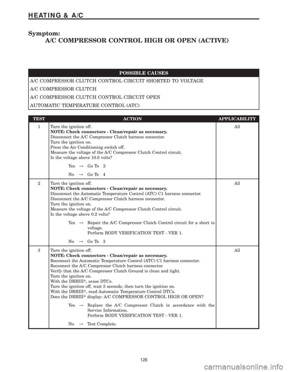
Symptom:
A/C COMPRESSOR CONTROL HIGH OR OPEN (ACTIVE)
POSSIBLE CAUSES
A/C COMPRESSOR CLUTCH CONTROL CIRCUIT SHORTED TO VOLTAGE
A/C COMPRESSOR CLUTCH
A/C COMPRESSOR CLUTCH CONTROL CIRCUIT OPEN
AUTOMATIC TEMPERATURE CONTROL (ATC)
TEST ACTION APPLICABILITY
1 Turn the ignition off.
NOTE: Check connectors - Clean/repair as necessary.
Disconnect the A/C Compressor Clutch harness connector.
Turn the ignition on.
Press the Air Conditioning switch off.
Measure the voltage of the A/C Compressor Clutch Control circuit.
Is the voltage above 10.0 volts?All
Ye s!Go To 2
No!Go To 4
2 Turn the ignition off.
NOTE: Check connectors - Clean/repair as necessary.
Disconnect the Automatic Temperature Control (ATC) C1 harness connector.
Disconnect the A/C Compressor Clutch harness connector.
Turn the ignition on.
Measure the voltage of the A/C Compressor Clutch Control circuit.
Is the voltage above 0.2 volts?All
Ye s!Repair the A/C Compressor Clutch Control circuit for a short to
voltage.
Perform BODY VERIFICATION TEST - VER 1.
No!Go To 3
3 Turn the ignition off.
NOTE: Check connectors - Clean/repair as necessary.
Reconnect the Automatic Temperature Control (ATC) C1 harness connector.
Reconnect the A/C Compressor Clutch harness connector.
Verify that the A/C Compressor Clutch Ground is clean and tight.
Turn the ignition on.
With the DRBIIIt, erase DTCs.
Turn the ignition off, wait 5 seconds, then turn the ignition on.
With the DRBIIIt, read Automatic Temperature Control DTCs.
Does the DRBIIItdisplay: A/C COMPRESSOR CONTROL HIGH OR OPEN?All
Ye s!Replace the A/C Compressor Clutch in accordance with the
Service Information.
Perform BODY VERIFICATION TEST - VER 1.
No!Test Complete.
128
HEATING & A/C
Page 144 of 2305

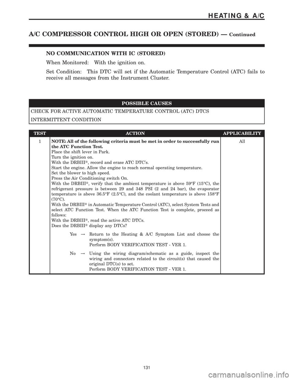
NO COMMUNICATION WITH IC (STORED)
When Monitored: With the ignition on.
Set Condition: This DTC will set if the Automatic Temperature Control (ATC) fails to
receive all messages from the Instrument Cluster.
POSSIBLE CAUSES
CHECK FOR ACTIVE AUTOMATIC TEMPERATURE CONTROL (ATC) DTCS
INTERMITTENT CONDITION
TEST ACTION APPLICABILITY
1NOTE: All of the following criteria must be met in order to successfully run
the ATC Function Test.
Place the shift lever in Park.
Turn the ignition on.
With the DRBIIIt, record and erase ATC DTC's.
Start the engine. Allow the engine to reach normal operating temperature.
Set the blower to high speed.
Press the Air Conditioning switch On.
With the DRBIIIt, verify that the ambient temperature is above 59ÉF (15ÉC), the
refrigerant pressure is between 29 and 348 PSI (2 and 24 bar), the evaporator
temperature is above 36.5ÉF (2.5ÉC), and the coolant temperature is above 158ÉF
(70ÉC).
With the DRBIIItin Automatic Temperature Control (ATC), select System Tests and
select ATC Function Test. When the ATC Function Test is complete, proceed as
follows:
With the DRBIIIt, read the active ATC DTCs.
Does the DRBIIItdisplay any DTCs?All
Ye s!Return to the Heating & A/C Symptom List and choose the
symptom(s).
Perform BODY VERIFICATION TEST - VER 1.
No!Using the wiring diagram/schematic as a guide, inspect the
wiring and connectors related to the circuit(s) that caused the
original DTC(s) to set.
Perform BODY VERIFICATION TEST - VER 1.
131
HEATING & A/C
A/C COMPRESSOR CONTROL HIGH OR OPEN (STORED) ÐContinued
Page 145 of 2305

Symptom:
A/C COMPRESSOR CONTROL SHORTED LOW (ACTIVE)
POSSIBLE CAUSES
A/C COMPRESSOR CLUTCH
A/C COMPRESSOR CLUTCH CONTROL CIRCUIT SHORTED TO GROUND
A/C COMPRESSOR CLUTCH CONTROL CIRCUIT SHORTED TO GROUND CIRCUIT
A/C COMPRESSOR CLUTCH CONTROL CIRCUIT SHORTED TO SENSOR GROUND CIRCUIT
AUTOMATIC TEMPERATURE CONTROL (ATC)
TEST ACTION APPLICABILITY
1 Turn the ignition on.
Press the Air Conditioning switch off.
Turn the ignition off.
Disconnect the A/C Compressor Clutch harness connector.
Turn the ignition on.
With the DRBIIIt, record and erase Automatic Temperature Control DTCs.
Turn the ignition off, wait 5 seconds, then turn the ignition on.
With the DRBIIIt, read the Automatic Temperature Control DTCs.
Does the DRBIIItdisplay: A/C COMPRESSOR CONTROL HIGH OR OPEN?All
Ye s!Replace the A/C Compressor Clutch in accordance with the
Service Information.
Perform BODY VERIFICATION TEST - VER 1.
No!Go To 2
2 Turn the ignition off.
Disconnect the A/C Compressor Clutch harness connector.
Disconnect the Automatic Temperature Control (ATC) C1 harness connector.
Measure the resistance between ground and the A/C Compressor Clutch Control
circuit.
Is the resistance below 10k ohms?All
Ye s!Repair the A/C Compressor Clutch Control circuit for a short to
ground.
Perform BODY VERIFICATION TEST - VER 1.
No!Go To 3
3 Turn the ignition off.
Disconnect the A/C Compressor Clutch harness connector.
Disconnect the Automatic Temperature Control (ATC) C1 harness connector.
Measure the resistance between the A/C Compressor Clutch Control circuit and the
Ground circuit in the Automatic Temperature Control C1 harness connector.
Is the resistance below 10k ohms?All
Ye s!Repair the A/C Compressor Clutch Control circuit for a short to
the Ground circuit.
Perform BODY VERIFICATION TEST - VER 1.
No!Go To 4
132
HEATING & A/C
Page 152 of 2305

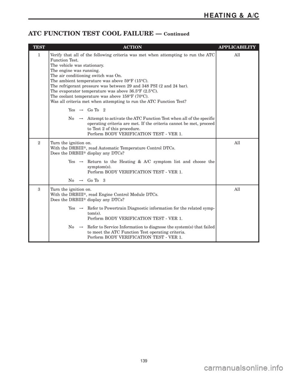
TEST ACTION APPLICABILITY
1 Verify that all of the following criteria was met when attempting to run the ATC
Function Test.
The vehicle was stationary.
The engine was running.
The air conditioning switch was On.
The ambient temperature was above 59ÉF (15ÉC).
The refrigerant pressure was between 29 and 348 PSI (2 and 24 bar).
The evaporator temperature was above 36.5ÉF (2.5ÉC).
The coolant temperature was above 158ÉF (70ÉC).
Was all criteria met when attempting to run the ATC Function Test?All
Ye s!Go To 2
No!Attempt to activate the ATC Function Test when all of the specific
operating criteria are met. If the criteria cannot be met, proceed
to Test 2 of this procedure.
Perform BODY VERIFICATION TEST - VER 1.
2 Turn the ignition on.
With the DRBIIIt, read Automatic Temperature Control DTCs.
Does the DRBIIItdisplay any DTCs?All
Ye s!Return to the Heating & A/C symptom list and choose the
symptom(s).
Perform BODY VERIFICATION TEST - VER 1.
No!Go To 3
3 Turn the ignition on.
With the DRBIIIt, read Engine Control Module DTCs.
Does the DRBIIItdisplay any DTCs?All
Ye s!Refer to Powertrain Diagnostic information for the related symp-
tom(s).
Perform BODY VERIFICATION TEST - VER 1.
No!Refer to Service Information to diagnose the system(s) that failed
to meet the ATC Function Test operating criteria.
Perform BODY VERIFICATION TEST - VER 1.
139
HEATING & A/C
ATC FUNCTION TEST COOL FAILURE ÐContinued
Page 155 of 2305

Symptom:
AUX FAN RELAY CONTROL SHORTED LOW (ACTIVE)
POSSIBLE CAUSES
A/C AUXILIARY FAN RELAY
A/C AUXILIARY FAN RELAY HIGH SIDE CONTROL CIRCUIT SHORTED TO GROUND
A/C AUXILIARY FAN RELAY HIGH SIDE CONTROL CIRCUIT SHORTED TO GROUND CIRCUIT
AUTOMATIC TEMPERATURE CONTROL (ATC)
A/C AUXILIARY FAN RELAY HIGH SIDE CONTROL CKT SHORTED TO SENSOR GROUND CKT
TEST ACTION APPLICABILITY
1 Turn the ignition off.
Install a substitute relay in place of the A/C Auxiliary Fan Relay.
NOTE: All of the following criteria must be met in order to successfully run
the ATC Function Test.
Place the shift lever in Park.
Turn the ignition on.
With the DRBIIIt, record and erase ATC DTC's.
Start the engine. Allow the engine to reach normal operating temperature.
Set the blower to high speed.
Press the Air Conditioning switch On.
With the DRBIIIt, verify that the ambient temperature is above 59ÉF (15ÉC), the
refrigerant pressure is between 29 and 348 PSI (2 and 24 bar), the evaporator
temperature is above 36.5ÉF (2.5ÉC), and the coolant temperature is above 158ÉF
(70ÉC).
With the DRBIIItin Automatic Temperature Control (ATC), select System Tests and
select ATC Function Test. When the ATC Function Test is complete, proceed as
follows:
With the DRBIIIt, read the active ATC DTCs.
Does the DRBIIItdisplay: AUX FAN RELAY CONTROL SHORTED LOW?All
Ye s!Go To 2
No!Replace the original A/C Auxiliary Fan Relay in accordance with
the Service Information.
Perform BODY VERIFICATION TEST - VER 1.
2 Turn the ignition off.
Remove the substitute A/C Auxiliary Fan Relay from the relay center.
Disconnect the Automatic Temperature Control (ATC) C1 harness connector.
Measure the resistance between ground and the A/C Auxiliary Fan Relay High Side
Control circuit.
Is the resistance below 10K ohms?All
Ye s!Repair the A/C Auxiliary Fan Relay High Side Control circuit for
a short to ground. Reinstall the original A/C Auxiliary Fan Relay.
Perform BODY VERIFICATION TEST - VER 1.
No!Go To 3
142
HEATING & A/C
Page 159 of 2305

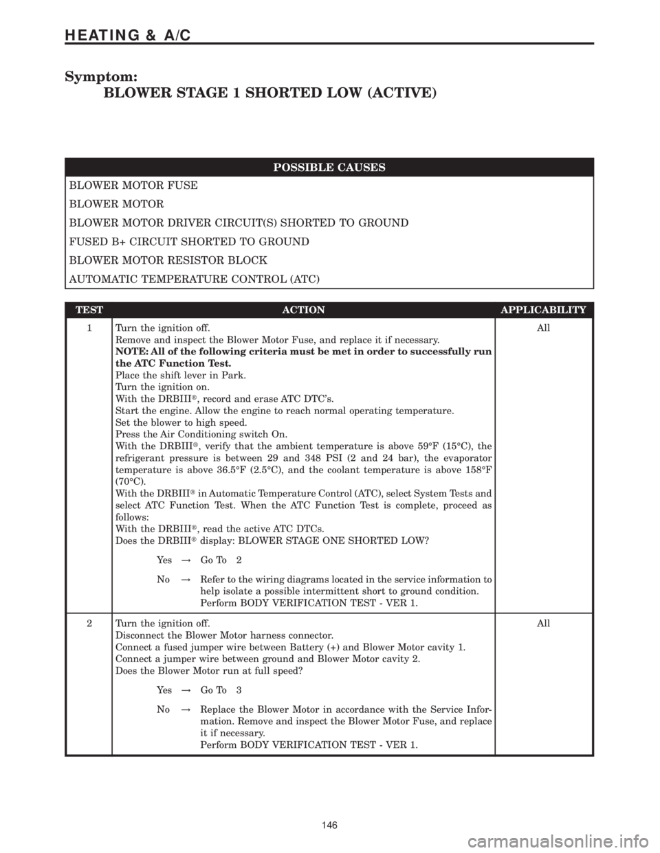
Symptom:
BLOWER STAGE 1 SHORTED LOW (ACTIVE)
POSSIBLE CAUSES
BLOWER MOTOR FUSE
BLOWER MOTOR
BLOWER MOTOR DRIVER CIRCUIT(S) SHORTED TO GROUND
FUSED B+ CIRCUIT SHORTED TO GROUND
BLOWER MOTOR RESISTOR BLOCK
AUTOMATIC TEMPERATURE CONTROL (ATC)
TEST ACTION APPLICABILITY
1 Turn the ignition off.
Remove and inspect the Blower Motor Fuse, and replace it if necessary.
NOTE: All of the following criteria must be met in order to successfully run
the ATC Function Test.
Place the shift lever in Park.
Turn the ignition on.
With the DRBIIIt, record and erase ATC DTC's.
Start the engine. Allow the engine to reach normal operating temperature.
Set the blower to high speed.
Press the Air Conditioning switch On.
With the DRBIIIt, verify that the ambient temperature is above 59ÉF (15ÉC), the
refrigerant pressure is between 29 and 348 PSI (2 and 24 bar), the evaporator
temperature is above 36.5ÉF (2.5ÉC), and the coolant temperature is above 158ÉF
(70ÉC).
With the DRBIIItin Automatic Temperature Control (ATC), select System Tests and
select ATC Function Test. When the ATC Function Test is complete, proceed as
follows:
With the DRBIIIt, read the active ATC DTCs.
Does the DRBIIItdisplay: BLOWER STAGE ONE SHORTED LOW?All
Ye s!Go To 2
No!Refer to the wiring diagrams located in the service information to
help isolate a possible intermittent short to ground condition.
Perform BODY VERIFICATION TEST - VER 1.
2 Turn the ignition off.
Disconnect the Blower Motor harness connector.
Connect a fused jumper wire between Battery (+) and Blower Motor cavity 1.
Connect a jumper wire between ground and Blower Motor cavity 2.
Does the Blower Motor run at full speed?All
Ye s!Go To 3
No!Replace the Blower Motor in accordance with the Service Infor-
mation. Remove and inspect the Blower Motor Fuse, and replace
it if necessary.
Perform BODY VERIFICATION TEST - VER 1.
146
HEATING & A/C