2006 MERCEDES-BENZ SPRINTER drain bolt
[x] Cancel search: drain boltPage 763 of 2305
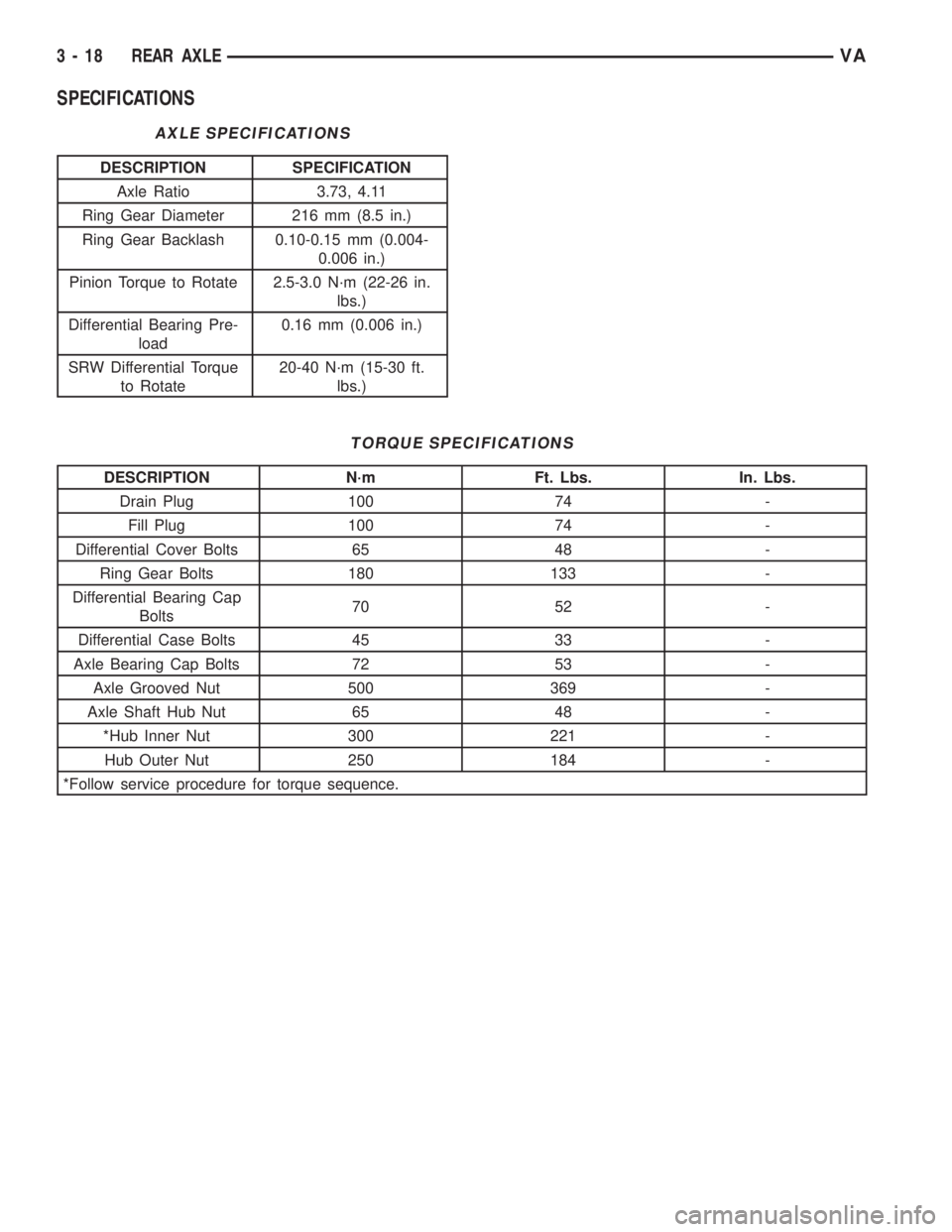
SPECIFICATIONS
AXLE SPECIFICATIONS
DESCRIPTION SPECIFICATION
Axle Ratio 3.73, 4.11
Ring Gear Diameter 216 mm (8.5 in.)
Ring Gear Backlash 0.10-0.15 mm (0.004-
0.006 in.)
Pinion Torque to Rotate 2.5-3.0 N´m (22-26 in.
lbs.)
Differential Bearing Pre-
load0.16 mm (0.006 in.)
SRW Differential Torque
to Rotate20-40 N´m (15-30 ft.
lbs.)
TORQUE SPECIFICATIONS
DESCRIPTION N´m Ft. Lbs. In. Lbs.
Drain Plug 100 74 -
Fill Plug 100 74 -
Differential Cover Bolts 65 48 -
Ring Gear Bolts 180 133 -
Differential Bearing Cap
Bolts70 52 -
Differential Case Bolts 45 33 -
Axle Bearing Cap Bolts 72 53 -
Axle Grooved Nut 500 369 -
Axle Shaft Hub Nut 65 48 -
*Hub Inner Nut 300 221 -
Hub Outer Nut 250 184 -
*Follow service procedure for torque sequence.
3 - 18 REAR AXLEVA
Page 776 of 2305
DIFFERENTIAL
REMOVAL
(1) Remove differential fill plug.
(2) Remove differential cover and drain fluid.
(3) Remove axle shafts.
(4) Mark bearing caps and housing for installation
reference.
(5) Remove differential bearing cap bolts.
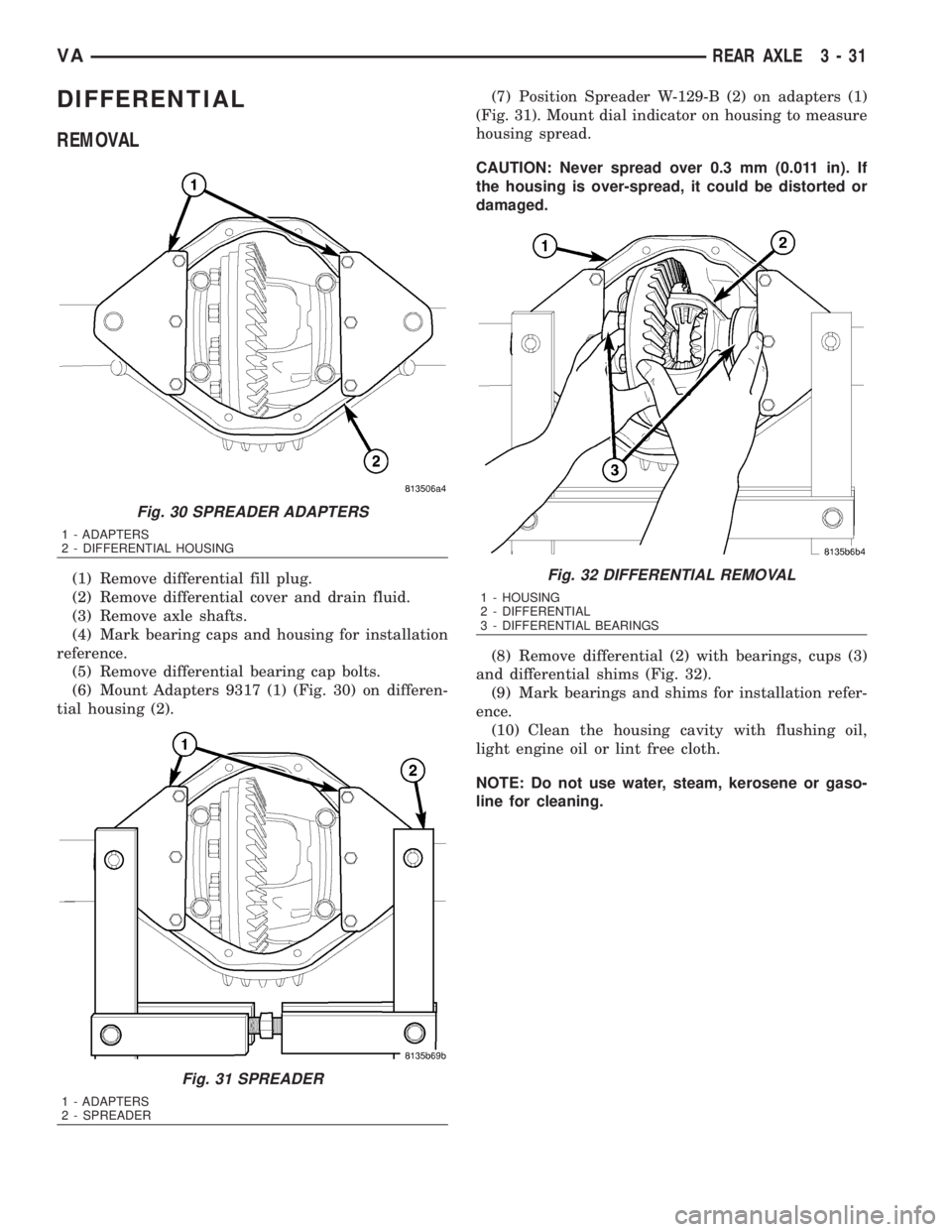
(6) Mount Adapters 9317 (1) (Fig. 30) on differen-
tial housing (2).(7) Position Spreader W-129-B (2) on adapters (1)
(Fig. 31). Mount dial indicator on housing to measure
housing spread.
CAUTION: Never spread over 0.3 mm (0.011 in). If
the housing is over-spread, it could be distorted or
damaged.
(8) Remove differential (2) with bearings, cups (3)
and differential shims (Fig. 32).
(9) Mark bearings and shims for installation refer-
ence.
(10) Clean the housing cavity with flushing oil,
light engine oil or lint free cloth.
NOTE: Do not use water, steam, kerosene or gaso-
line for cleaning.
Fig. 30 SPREADER ADAPTERS
1 - ADAPTERS
2 - DIFFERENTIAL HOUSING
Fig. 31 SPREADER
1 - ADAPTERS
2 - SPREADER
Fig. 32 DIFFERENTIAL REMOVAL
1 - HOUSING
2 - DIFFERENTIAL
3 - DIFFERENTIAL BEARINGS
VAREAR AXLE 3 - 31
Page 786 of 2305
(13) Connect propeller shaft to pinion flange.
NOTE: On dual rear wheel axle install axle shafts.
(14) Pour in oil up to bottom edge of oil filler hole
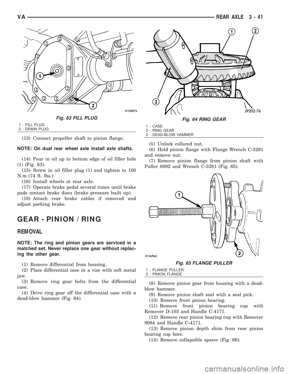
(1) (Fig. 63).
(15) Screw in oil filler plug (1) and tighten to 100
N´m (74 ft. lbs.).
(16) Install wheels at rear axle.
(17) Operate brake pedal several times until brake
pads contact brake discs (brake pressure built up).
(18) Attach rear brake cables if removed and
adjust parking brake.
GEAR - PINION / RING
REMOVAL
NOTE: The ring and pinion gears are serviced in a
matched set. Never replace one gear without replac-
ing the other gear.
(1) Remove differential from housing.
(2) Place differential case in a vise with soft metal
jaw.
(3) Remove ring gear bolts from the differential
case.
(4) Drive ring gear off the differential case with a
dead-blow hammer (Fig. 64).(5) Unlock collared nut.
(6) Hold pinion flange with Flange Wrench C-3281
and remove nut.
(7) Remove pinion flange from pinion shaft with
Puller 8892 and Wrench C-3281 (Fig. 65).
(8) Remove pinion gear from housing with a dead-
blow hammer.
(9) Remove pinion shaft seal with a seal pick.
(10) Remove front pinion bearing.
(11) Remove front pinion bearing cup with
Remover D-103 and Handle C-4171.
(12) Remove rear pinion bearing cup with Remover
9084 and Handle C-4171.
(13) Remove pinion depth shim from rear pinion
bearing cup bore.
(14) Remove collapsible spacer (Fig. 66).
Fig. 63 FILL PLUG
1 - FILL PLUG
2 - DRAIN PLUG
Fig. 64 RING GEAR
1 - CASE
2 - RING GEAR
3 - DEAD-BLOW HAMMER
Fig. 65 FLANGE PULLER
1 - FLANGE PULLER
2 - PINION FLANGE
VAREAR AXLE 3 - 41
Page 843 of 2305

(3) Refill coolant system to proper level with
proper mixture of coolant (Refer to 7 - COOLING/
ENGINE/COOLANT - STANDARD PROCEDURE).
(4) Install engine cover (Refer to 9 - ENGINE -
INSTALLATION).
(5) Connect negative battery cable.
WARNING: Use extreme caution when engine is
operating. Do not stand in a direct line with fan. do
not put your hands near pulleys, belts or fan. Do
not wear loose clothes.
(6) Start engine and inspect for leaks.
ENGINE COOLANT THERMO-
STAT
REMOVAL
WARNING: RISK OF INJURY TO SKIN AND EYES
FROM SCALDING WITH HOT COOLANT. RISK OF
POISONING FROM SWALLOWING COOLANT. DO
NOT OPEN COOLING SYSTEM UNLESS COOLANT
TEMPERATURE IS BELOW 90ÉC (194ÉF). OPEN CAP
SLOWLY TO RELEASE PRESSURE. STORE COOL-
ANT IN SUITABLE AND APPROPRIATELY MARKED
CONTAINER. WEAR PROTECTIVE GLOVES,
CLOTHES AND EYE WEAR.
NOTE: Inspect condition of all clamps and hoses,
replace as necessary.
(1) Disconnect negative battery cable.
(2) Partially drain engine coolant (Refer to 7 -
COOLING/ENGINE/COOLANT - STANDARD PRO-
CEDURE).
(3) Unplug connector, pull off locking element and
pull out coolant temperature sensor.
(4) Detach air intake hose at charge air distribu-
tion pipe.
(5) Detach coolant hoses at thermostat housing.
(6) Unscrew cap at oil filter housing.
(7) Remove thermostat housing (Fig. 8).(8) Clean all sealing surfaces.
INSTALLATION
(1) Clean all sealing surfaces.
(2) Position and install thermostat housing with
new gasket (Fig. 8). Tighten bolts to 9N´m (80
lbs.in.).
NOTE: Inspect condition of all clamps and hoses,
replace as necessary.
(3) Install cap at oil filter housing.
(4) Connect coolant hoses and vent hose (Fig. 8).
(5) Attach air intake hose at charge air distribu-
tion pipe.
(6) Close coolant drain.
(7) Connect negative battery cable.
(8) Fill coolant system to proper level with appro-
priate coolant mixture (Refer to 7 - COOLING/EN-
GINE/COOLANT - STANDARD PROCEDURE).
WARNING: USE EXTREME CAUTION WHEN ENGINE
IS OPERATING. DO NOT STAND IN DIRECT LINE
WITH FAN. DO NOT PUT YOUR HANDS NEAR PUL-
LEYS, BELTS OR FAN. DO NOT WEAR LOOSE
CLOTHES.
(9) Start engine and inspect for leaks.
Fig. 8 THERMOSTAT HOUSING ASSEMBLY
1 - O-RING
2 - CLAMP
3 - COOLANT TEMPERATURE SENSOR
4 - FUEL LINE W/BRACKET
5 - THERMOSTAT HOUSING ASSEMBLY
6 - COOLANT HOSE
7 - CLAMP
8 - COOLANT HOSE
9 - GASKET
7 - 16 ENGINEVA
Page 844 of 2305
FAN DRIVE VISCOUS CLUTCH
REMOVAL
(1) For fan drive viscous clutch removal refer to
(Refer to 7 - COOLING/ENGINE/RADIATOR FAN -
REMOVAL).
INSTALLATION
(1) For fan drive viscous clutch installation refer to
(Refer to 7 - COOLING/ENGINE/RADIATOR FAN -
INSTALLATION).
RADIATOR
REMOVAL
WARNING: RISK OF INJURY TO SKIN AND EYES
FROM SCALDING WITH HOT COOLANT. RISK OF
POISONING FROM SWALLOWING COOLANT. DO
NOT OPEN COOLING SYSTEM UNLESS COOLANT
TEMPERATURE IS BELOW 90ÉC (194ÉF). OPEN CAP
SLOWLY TO RELEASE PRESSURE. STORE COOL-
ANT IN SUITABLE AND APPROPRIATELY MARKED
CONTAINER. WEAR PROTECTIVE GLOVES,
CLOTHES AND EYE WEAR.
NOTE: Capture all residual fluid spillage and store
in suitably marked containers. Inspect condition of
all clamps and hoses, replace as necessary.
(1) Drain coolant from radiator only (Refer to 7 -
COOLING/ENGINE/COOLANT - STANDARD PRO-
CEDURE).
(2) Remove headlamps.
(3) Remove front cross member together with front
grille.
(4) Remove front bumper.
(5) Remove bolts holding air charge hose to sheet
metal and intercooler.
(6) Detach air intake pipe at the body (Fig. 9).
(7) Detach both coolant hoses at the coolant reser-
voir (Fig. 9).
VAENGINE 7 - 17
Page 849 of 2305
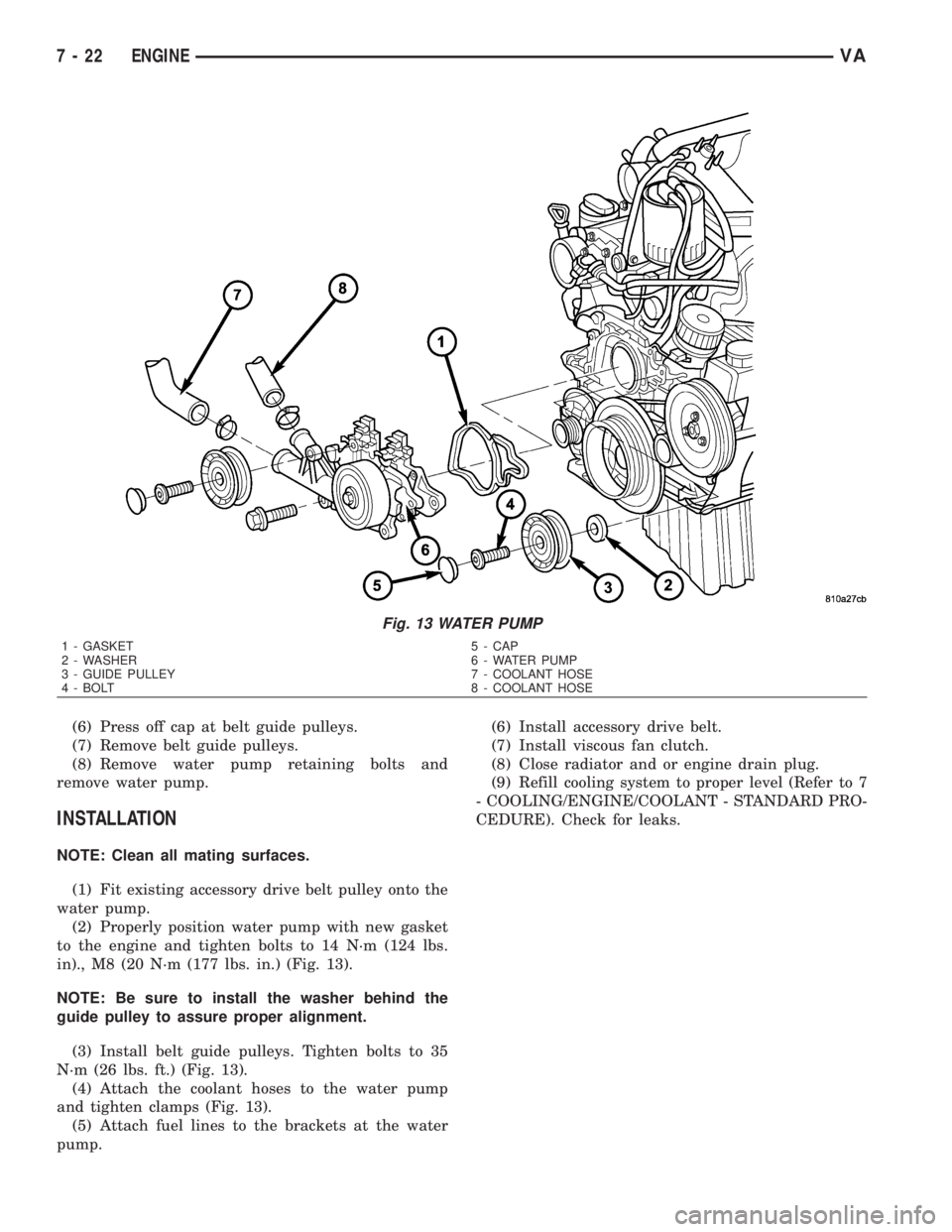
(6) Press off cap at belt guide pulleys.
(7) Remove belt guide pulleys.
(8) Remove water pump retaining bolts and
remove water pump.
INSTALLATION
NOTE: Clean all mating surfaces.
(1) Fit existing accessory drive belt pulley onto the
water pump.
(2) Properly position water pump with new gasket
to the engine and tighten bolts to 14 N´m (124 lbs.
in)., M8 (20 N´m (177 lbs. in.) (Fig. 13).
NOTE: Be sure to install the washer behind the
guide pulley to assure proper alignment.
(3) Install belt guide pulleys. Tighten bolts to 35
N´m (26 lbs. ft.) (Fig. 13).
(4) Attach the coolant hoses to the water pump
and tighten clamps (Fig. 13).
(5) Attach fuel lines to the brackets at the water
pump.(6) Install accessory drive belt.
(7) Install viscous fan clutch.
(8) Close radiator and or engine drain plug.
(9) Refill cooling system to proper level (Refer to 7
- COOLING/ENGINE/COOLANT - STANDARD PRO-
CEDURE). Check for leaks.
Fig. 13 WATER PUMP
1 - GASKET 5 - CAP
2 - WASHER 6 - WATER PUMP
3 - GUIDE PULLEY 7 - COOLANT HOSE
4 - BOLT 8 - COOLANT HOSE
7 - 22 ENGINEVA
Page 881 of 2305

volt, clean and tighten the battery negative cable
eyelet terminal connection to the engine block.
Repeat the test. If the reading is still above 0.2 volt,
replace the faulty battery negative cable.
REMOVAL
(1) Turn the ignition switch to the Off position. Be
certain that all electrical accessories are turned off.
(2) Disconnect and isolate the remote battery neg-
ative cable terminal.
(3) One at a time, trace and disconnect the battery
cable retaining pushpins, fasteners and routing clips
until the cables are free from the vehicle.
(4) Feed the battery cable assembly out of the
vehicle.
INSTALLATION
(1) Position the battery cable in the vehicle.
(2) One at a time, install the battery cable retain-
ing pushpins, fasteners and routing clips until the
cable is installed exactly in the factory installed loca-
tion in the vehicle. Refer to the Wiring Diagram sec-
tion of the service manual for reference.
(3) Connect the battery negative cable terminal.
BATTERY TRAY
DESCRIPTION
The battery is mounted in a stamped steel battery
tray located in the left front corner of the engine
compartment. The battery tray is secured with bolts
to the left front wheelhouse inner steel panel. A hole
in the bottom of the battery tray is fitted with aformed drain tube. A second hole in the bottom of the
tray is fitted with a battery temperature sensor.
OPERATION
The battery tray provides a mounting location and
support for the vehicle battery. The battery tray sup-
port supports the battery tray and provides an
anchor point for the inboard battery hold down hard-
ware. The battery tray and the battery hold down
hardware combine to secure and stabilize the battery
in the engine compartment, which prevents battery
movement during vehicle operation. Unrestrained
battery movement during vehicle operation could
result in damage to the vehicle, the battery or both.
The battery tray drain tube directs spilled water or
electrolyte from a leaking battery to the ground
through another hole in the front extension of the
left front wheelhouse inner panel.
REMOVAL
(1) Remove the battery from the battery tray.
(Refer to 8 - ELECTRICAL/BATTERY SYSTEM/BAT-
TERY - REMOVAL).
(2) Remove the battery temperature sensor from
the battery tray. (Refer to 8 - ELECTRICAL/CHARG-
ING/BATTERY TEMPERATURE SENSOR -
REMOVAL).
(3) Remove the bolts that secure the battery tray
to the battery tray support.
(4) Remove the battery tray from the vehicle.
INSTALLATION
(1) Clean and inspect the battery tray. (Refer to 8 -
ELECTRICAL/BATTERY SYSTEM - CLEANING).
(2) Position the battery tray onto the battery tray
support.
(3) Install and tighten the bolts that secure the
battery tray to the battery tray support. Tighten the
screws to 11.8 N´m (105 in. lbs.).
(4) Install the battery temperature sensor onto the
battery tray. (Refer to 8 - ELECTRICAL/CHARGING/
BATTERY TEMPERATURE SENSOR - INSTALLA-
TION).
(5) Install the battery onto the battery tray. (Refer
to 8 - ELECTRICAL/BATTERY SYSTEM/BATTERY -
INSTALLATION).
Fig. 12 Test Ground Circuit Resistance - Typical
1 - VOLTMETER
2 - BATTERY
3 - ENGINE GROUND
8F - 16 BATTERY SYSTEMVA
Page 1583 of 2305
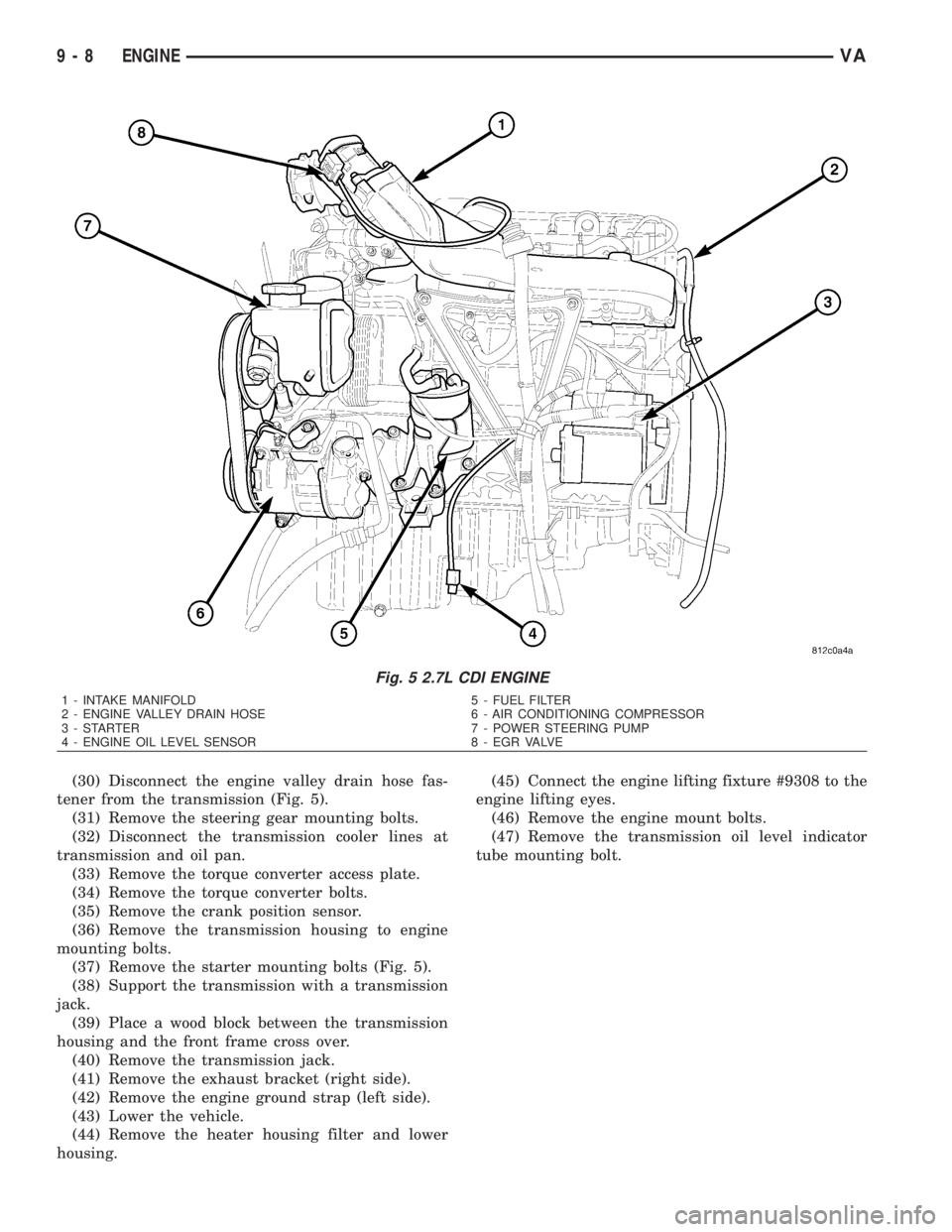
(30) Disconnect the engine valley drain hose fas-
tener from the transmission (Fig. 5).
(31) Remove the steering gear mounting bolts.
(32) Disconnect the transmission cooler lines at
transmission and oil pan.
(33) Remove the torque converter access plate.
(34) Remove the torque converter bolts.
(35) Remove the crank position sensor.
(36) Remove the transmission housing to engine
mounting bolts.
(37) Remove the starter mounting bolts (Fig. 5).
(38) Support the transmission with a transmission
jack.
(39) Place a wood block between the transmission
housing and the front frame cross over.
(40) Remove the transmission jack.
(41) Remove the exhaust bracket (right side).
(42) Remove the engine ground strap (left side).
(43) Lower the vehicle.
(44) Remove the heater housing filter and lower
housing.(45) Connect the engine lifting fixture #9308 to the
engine lifting eyes.
(46) Remove the engine mount bolts.
(47) Remove the transmission oil level indicator
tube mounting bolt.
Fig. 5 2.7L CDI ENGINE
1 - INTAKE MANIFOLD 5 - FUEL FILTER
2 - ENGINE VALLEY DRAIN HOSE 6 - AIR CONDITIONING COMPRESSOR
3 - STARTER 7 - POWER STEERING PUMP
4 - ENGINE OIL LEVEL SENSOR 8 - EGR VALVE
9 - 8 ENGINEVA