2006 MERCEDES-BENZ SPRINTER wheel bolts
[x] Cancel search: wheel boltsPage 16 of 2305
When supplied with the proper electrical signal, the
inflator discharged the gas directly into the cush-
ion. The airbag cannot be repaired, and must be
replaced if deployed or in any way damaged.
WARNING: THE DRIVER AIRBAG MODULE
CONTAINS ARGON GAS PRESSURIZED TO
OVER 17236.89 Kpa (2500 PSI). DO NOT
ATTEMPT TO DISMANTLE AN AIRBAG
MODULE OR TAMPER WITH ITS INFLATOR.
DO NOT PUNCTURE, INCINERATE, OR
BRING INTO CONTACT WITH ELECTRICITY.
DO NOT STORE AT TEMPERATURE
EXCEEDING 93ÉC (200ÉF). REPLACE AIRBAG
SYSTEM COMPONENTS ONLY WITH PARTS
SPECIFIED IN THE CHRYSLER MOPAR
PARTS CATALOG. SUBSTITUTE PARTS MAY
APPEAR INTER-CHANGEABLE, BUT
INTERNAL DIFFERENCES MAY RESULT IN
INFERIOR OCCUPANT PROTECTION. THE
FASTENERS, SCREWS, AND BOLTS
ORIGINALLY USED FOR THE AIRBAG
SYSTEM COMPONENTS HAVE SPECIAL
COATINGS AND ARE SPECIFICALLY
DESIGNED FOR THE AIRBAG SYSTEM. THEY
MUST NEVER BE REPLACED WITH ANY
SUBSTITUTES. ANY TIME A NEW FASTENER
IS NEEDED, REPLACE IT WITH THE
CORRECT FASTENERS PROVIDED IN THE
SERVICE PACKAGE OR SPECIFIED IN THE
MOPAR PARTS CATALOG. FAILURE TO
TAKE THE PROPER PRECAUTIONS COULD
RESULT IN ACCIDENTAL AIRBAG
DEPLOYMENT AND PERSONAL INJURY OR
DEATH.
3.1.2 CLOCKSPRING
The clockspring is mounted on the steering col-
umn under the steering wheel. This assembly con-
sists of a plastic housing which contains a flat,
ribbon-like, electrically conductive tape that winds
and unwinds with the steering wheel rotation. The
clockspring is used to maintain a continuous elec-
trical circuit between the instrument panel wiring
and the driver airbag and the horn. The clockspring
must be properly centered when it is reinstalled on
the steering column following any service proce-
dure, or it could be damaged. The clockspring can-
not be repaired and it must be replaced.
3.1.3 PASSENGER AIRBAG
The Passenger Airbag is optional equipment.
When supplied with the proper electrical signal the
passenger airbag inflator discharges the gas di-rectly into the cushion. The airbag module cannot
be repaired, and must be replaced if deployed or in
any way damaged.
WARNING: THE PASSENGER AIRBAG
MODULE CONTAINS ARGON GAS
PRESSURIZED TO 17236.89 Kpa (2500 PSI).
DO NOT ATTEMPT TO DISMANTLE AN
AIRBAG MODULE OR TAMPER WITH ITS
INFLATOR. DO NOT PUNCTURE,
INCINERATE, OR BRING INTO CONTACT
WITH ELECTRICITY. DO NOT STORE AT
TEMPERATURE EXCEEDING 93ÉC (200ÉF).
REPLACE AIRBAG SYSTEM COMPONENTS
ONLY WITH PARTS SPECIFIED IN THE
MOPAR PARTS CATALOG. SUBSTITUTE
PARTS MAY APPEAR INTER-CHANGEABLE,
BUT INTERNAL DIFFERENCES MAY RESULT
IN INFERIOR OCCUPANT PROTECTION. THE
FASTENERS, SCREWS, AND BOLTS
ORIGINALLY USED FOR THE AIRBAG
SYSTEM COMPONENTS HAVE SPECIAL
COATINGS AND ARE SPECIFICALLY
DESIGNED FOR THE AIRBAG SYSTEM. THEY
MUST NEVER BE REPLACED WITH ANY
SUBSTITUTES. ANY TIME A NEW FASTENER
IS NEEDED, REPLACE IT WITH THE
CORRECT FASTENERS PROVIDED IN THE
SERVICE PACKAGE OR SPECIFIED IN THE
MOPAR PARTS CATALOG. FAILURE TO
TAKE THE PROPER PRECAUTIONS COULD
RESULT IN ACCIDENTAL AIRBAG
DEPLOYMENT AND PERSONAL INJURY OR
DEATH.
3.1.4 SEAT BELT TENSIONERS
Front seat belt systems incorporate a Driver and
optional Passenger Seat Belt Tensioner Retractors.
At the onset of an impact event each tensioner uses
a pyrotechnic device, which is triggered simulta-
neously with the front airbags, to rapidly retract
the seat belts. With the slack removed, the occu-
pant's forward motion in an impact will be reduced
as will the likelihood of contacting interior compo-
nents. After an impact that deploys the airbag, the
seat belt tensioner assembly must be replaced. The
ACM module monitors the Seat Belt Tensioners
circuit resistance and reports active and stored
DTCs if any problem is found. Follow all of the
safety procedures when servicing tensioner.
3.1.5 SPECIAL TOOLS
Airbag load tools 8310 and 8443 are used in some
airbag diagnostic test. The load tools contain fixed
resistive loads, jumpers and adapters. The fixed
3
GENERAL INFORMATION
Page 732 of 2305

(6) Seperate the tie rod off the steering knuckle
(Fig. 8) using special tool C-3894±A.
NOTE: In order to remove tension from the strut,
Raise the lower control arm approximately 10 mm
with a jack.
(7) Remove the strut bolts from the steering
knuckle (Fig. 8).
(8) Remove the stop plate bolts and rotate the
plate upwards with the stabilizer link attached (Fig.
8).
(9) Lower the lower control arm.
(10) Remove the lower ball joint nut from the
steering knuckle (Fig. 8).
(11) Separate the lower ball joint from the knuckle
using special tool 9282.
(12) Remove the lower control arm nuts and bolts
from the frame (Fig. 8).
(13) Remove the lower control arm.
INSTALLATION
(1) Install the lower control arm to the frame.
Hand tighten the nuts and bolts.
NOTE: In order to remove tension from the strut,
Raise the lower control arm approximately 10 mm
with a jack.(2) Install the lower ball joint into the steering
knuckle. Tighten to 280 N´m (206 ft. lbs.).
(3) Install the strut bolts to the steering knuckle
(Fig. 8). Tighten to 185 N´m (136 ft. lbs.).
(4) Install the stop plate (Refer to 2 - SUSPEN-
SION/FRONT/SPRING STOP PLATES - INSTALLA-
TION).
(5) Lower the lower control arm.
(6) Attach the tie rod to the steering knuckle (Fig.
8). Tighten the nut to 130 N´m (96 ft. lbs.)
(7) Install the disc brake caliper adapter (Refer to
5 - BRAKES/HYDRAULIC/MECHANICAL/DISC
BRAKE CALIPER ADAPTER - INSTALLATION)
(Fig. 8).
(8) Install the front tire & wheel assembly (Refer
to 22 - TIRES/WHEELS/WHEELS - INSTALLA-
TION).
(9) Lower the vehicle.
(10) Remove the spring blocks between the spring
and the spring clamp plates, While the vehicles
wheels are on the ground.
(11) Roll the vehicle approximately 1 mm forwards
and the backwards, and rock firmly.
(12) Tighten the lower control arm nuts and bolts
to the frame to 150 N´m (110 ft. lbs.) (Fig. 8).
(13) Apply brake to actuate brake pressure.
SPRING
REMOVAL
(1)To do this next step the vehicle must be
on the ground.Remove the front and rear bolts on
the left and right spring clamp plates (Fig. 9).
(2) Raise and support the vehicle.
(3) Remove the front wheels.
(4) Remove the brake caliper adapter (Refer to 5 -
BRAKES/HYDRAULIC/MECHANICAL/DISC
BRAKE CALIPER ADAPTER - REMOVAL).Do not
allow the caliper to hang by the hose, support
the caliper accordingly.
(5) Remove the ABS sensor from the mounting
bore in the steering knuckle (Fig. 9).
(6) Remove the outer tie rod retaining nut and
separate the tie rod from the knuckle (Fig. 9) using
special tool C-3894±A.
NOTE: In order to remove tension from the strut,
Raise the lower control arm approximately 10 mm
with a jack.
(7) Remove the strut bolts from the steering
knuckle.
(8) Remove both stop plate bolts and rotate the
plates upwards with the stabilizer link attached.
(9) Lower the lower control arm.
(10) Remove the lower ball joint nut from the
steering knuckle.
Fig. 8 LOWER CONTROL ARM
1 - STRUT
2 - LOWER CONTROL ARM BOLT
3 - STOP PLATE BOLT
4 - STOP PLATE
5 - CALIPER ADPTER BOLT
6 - DISC BRAKE CALIPER
7 - LOCKING BOLT
8 - DISC BRAKE ROTOR
9 - OUTER TIE ROD END RETAINING NUT
10 - OUTER TIE ROD END
11 - LOWER BALL JOINT NUT
12 - LOWER BALL JOINT
13 - LOWER CONTROL ARM NUTS
14 - STRUT BOLT
VAFRONT 2 - 7
Page 733 of 2305

(11) Separate the lower ball joint from the knuckle
using special tool 9282.
(12) Remove the lower control arm nuts and bolts
from the frame.
(13) Remove the lower control arm from the frame
(Fig. 9).
NOTE: To avoid damaging the transverse leaf
spring, cushion the pad on the jack accordingly.
(14) Support the transverse leaf spring in the cen-
ter with a jack.
(15) Remove the left and right spring clamp plates
(Refer to 2 - SUSPENSION/FRONT/SPRING CLAMP
PLATES - REMOVAL) (Fig. 9).
NOTE: The upper spring blocks between the engine
cradle and the spring are color coded, Make sure
not to mix the blocks per sides. The blocks are dif-
ferent in sizes to accommodate the weight of the
vehicle and driver in order for the vehicle to sit
level.
(16) Lower the jack and remove the transverse leaf
spring towards the side.INSTALLATION
NOTE: To avoid damaging the transverse leaf
spring, cushion the pad on the jack accordingly.
NOTE: Hand tighten all bolts until vehicle is on the
ground, unless the bushings may become distorted.
NOTE: The height blocks between the engine cradle
and the spring are color coded, Make sure not to
mix the blocks per sides. The blocks are different in
sizes to accommodate the weight of the vehicle and
driver in order for the vehicle to sit level.
(1) Install the transverse leaf spring in the center
with a jack with all the rubber mounts attached.
(2) Install the lower control arm to the frame (Fig.
9).
(3) Install the knuckle on the lower ball joint.
(4) Raise the lower control arm approximately 10
mm with a jack.
(5) Install both stop plate bolts to the lower control
arm
(6) Install the strut bolts to the steering knuckle.
(7) Reinstall the tie rod to the steering knuckle
(Fig. 9). Tighten to 150 N´m (110 ft. lbs.).
(8) Install the ABS sensor all the way into the
steering knuckle, the sensor will adjust automatically
when the vehicle is moved (Fig. 9).
(9) Install the disc brake caliper adapter (Fig. 9).
Tighten to 170 N´m (125 ft. lbs.).
(10) Install the front wheels.
(11) Lower the vehicle.
(12) Install the spring clamp plates (Fig. 9).
Tighten (M-10 bolts) to 65 N´m (48 ft. lbs.) (M-12
bolts) to 130 N´m (96 ft. lbs.).
(13) Roll the vehicle approximately 1 mm forwards
and the backwards, and rock firmly.
(14) Tighten the nuts on the lower control arm to
the frame to 150 N´m (110 ft. lbs.).
(15) Apply brake to actuate brake pressure.
SPRING CLAMP PLATES
REMOVAL
(1) Raise and support the vehicle.
(2) Install a jack under the lower ball joint and
lower the weight of the vehicle enough to allow a
wrench between the lower control arm and the
bracket tighten the nut.
(3) Remove the front and rear bolts to the spring
clamp plates.
(4) Remove the four inner retaining bolts and
nuts.
Fig. 9 FRONT SPRING
1 - NUT
2 - STRUT
3 - STOP PLATE
4 - STOP PLATE BOLT
5 - CALIPER ADAPTER BOLT
6 - DISC BRAKE CALIPER
7 - OUTER TIE ROD END NUT
8 - ABS SENSOR
9 - SPEED SENSOR
10 - LOWER CONTROL ARM RETAINING NUTS
11 - OUTER TIE ROD END
12 - RUBBER SPRING MOUNT
13 - SHEAR BUSHING
14 - SPRING CLAMP PLATE BOLT
15 - SPRING CLAMP PLATE
16 - LOWER RUBBER SPRING MOUNT
17 - SPRING
18 - STRUT BOLTS
19 - LOWER CONTROL ARM BOLTS
2 - 8 FRONTVA
Page 734 of 2305
(5) Remove the spring clamp plate and rubber
block.
(6) Remove the shear bushings from the front and
rear bolts.
INSTALLATION
(1) Install a jack under the lower ball joint and
lower the weight of the vehicle enough to allow a
wrench between the lower control arm and the
bracket tighten the nut.
(2) Fit one spring clamp plate together with the
lower spring rubber block.
(3) Install the bolt with the shear bushing on the
rear mounting,Do not tighten yet.
(4) Install the four retaining bolts for the spring
clamp plate. Tighten to 65 N´m (48 ft.lbs.).
(5) Align the holes for the front clamp plate joint
using a suitable drift (shear bushing not installed).
(6) Remove the alignment drift.
(7) Insert the shear bushing and retaining bolt
into the hole and tighten to 130 N´m (96 ft.lbs.).
(8) Remove the jack and lower the vehicle.
SPRING STOP PLATES
REMOVAL
(1) Raise and support the vehicle.
(2) Remove the tire and wheel assembly.
(3) Remove the lower end of the stabilizer link
from the stop plate.
(4) Remove the three bolts retaining the spring
stop plate from the lower control arm.
INSTALLATION
(1) Install the spring stop plate to the lower con-
trol arm. Tighten the bolts to 60 N´m (44 ft. lbs.).
(2) Install the stabilizer link to the spring stop
plate.
(3) Install the tire and wheel assembly.
(4) Lower the vehicle.
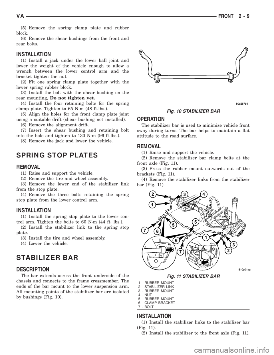
STABILIZER BAR
DESCRIPTION
The bar extends across the front underside of the
chassis and connects to the frame crossmember. The
ends of the bar mount to the lower suspension arm.
All mounting points of the stabilizer bar are isolated
by bushings (Fig. 10).
OPERATION
The stabilizer bar is used to minimize vehicle front
sway during turns. The bar helps to maintain a flat
attitude to the road surface.
REMOVAL
(1) Raise and support the vehicle.
(2) Remove the stabilizer bar clamp bolts at the
front axle (Fig. 11).
(3) Press the rubber mount outwards out of the
brackets (Fig. 11).
(4) Remove the stabilizer links from the stabilizer
bar (Fig. 11).
INSTALLATION
(1) Install the stabilizer links to the stabilizer bar
(Fig. 11).
(2) Install the stabilizer to the front axle (Fig. 11).
Fig. 10 STABILIZER BAR
Fig. 11 STABILIZER BAR
1 - RUBBER MOUNT
2 - STABILIZER LINK
3 - RUBBER MOUNT
4 - NUT
5 - RUBBER MOUNT
6 - CLAMP BRACKET
7 - BOLT
VAFRONT 2 - 9
Page 735 of 2305
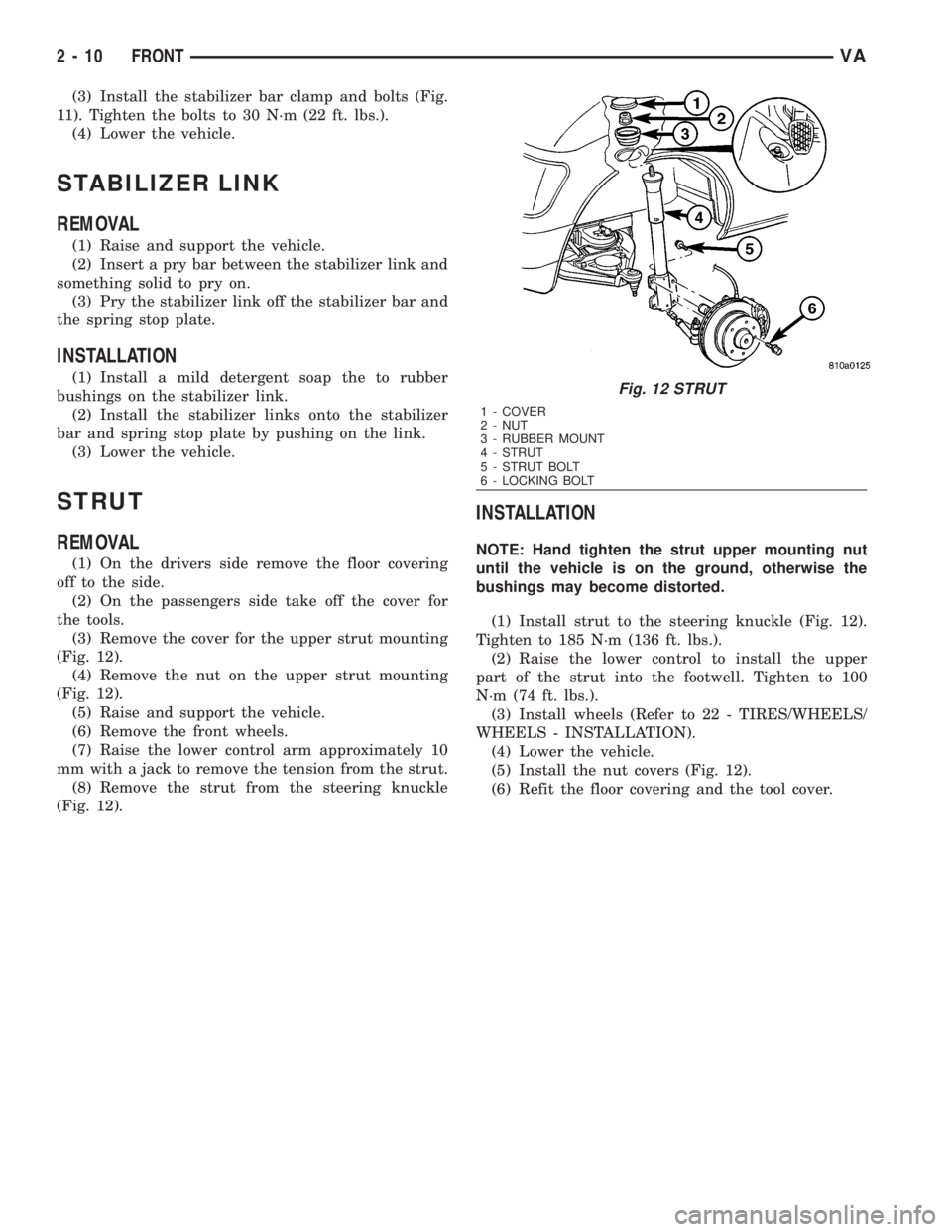
(3) Install the stabilizer bar clamp and bolts (Fig.
11). Tighten the bolts to 30 N´m (22 ft. lbs.).
(4) Lower the vehicle.
STABILIZER LINK
REMOVAL
(1) Raise and support the vehicle.
(2) Insert a pry bar between the stabilizer link and
something solid to pry on.
(3) Pry the stabilizer link off the stabilizer bar and
the spring stop plate.
INSTALLATION
(1) Install a mild detergent soap the to rubber
bushings on the stabilizer link.
(2) Install the stabilizer links onto the stabilizer
bar and spring stop plate by pushing on the link.
(3) Lower the vehicle.
STRUT
REMOVAL
(1) On the drivers side remove the floor covering
off to the side.
(2) On the passengers side take off the cover for
the tools.
(3) Remove the cover for the upper strut mounting
(Fig. 12).
(4) Remove the nut on the upper strut mounting
(Fig. 12).
(5) Raise and support the vehicle.
(6) Remove the front wheels.
(7) Raise the lower control arm approximately 10
mm with a jack to remove the tension from the strut.
(8) Remove the strut from the steering knuckle
(Fig. 12).
INSTALLATION
NOTE: Hand tighten the strut upper mounting nut
until the vehicle is on the ground, otherwise the
bushings may become distorted.
(1) Install strut to the steering knuckle (Fig. 12).
Tighten to 185 N´m (136 ft. lbs.).
(2) Raise the lower control to install the upper
part of the strut into the footwell. Tighten to 100
N´m (74 ft. lbs.).
(3) Install wheels (Refer to 22 - TIRES/WHEELS/
WHEELS - INSTALLATION).
(4) Lower the vehicle.
(5) Install the nut covers (Fig. 12).
(6) Refit the floor covering and the tool cover.
Fig. 12 STRUT
1 - COVER
2 - NUT
3 - RUBBER MOUNT
4 - STRUT
5 - STRUT BOLT
6 - LOCKING BOLT
2 - 10 FRONTVA
Page 739 of 2305
SPRING
DESCRIPTION
The rear suspension system uses a multi-leaf
springs and a solid drive axle. The forward end of the
springs are mounted to the body rail hangers
through rubber bushings. The rearward end of the
springs are attached to the body by the use of shack-
les. The spring and shackles use rubber bushings.
OPERATION
The springs control ride quality and maintain vehi-
cle ride height. The shackles allow the springs to
change their length as the vehicle moves over various
road conditions.
REMOVAL
REMOVAL - (SRW)
(1) Raise and support the vehicle.
(2) Support the rear axle.
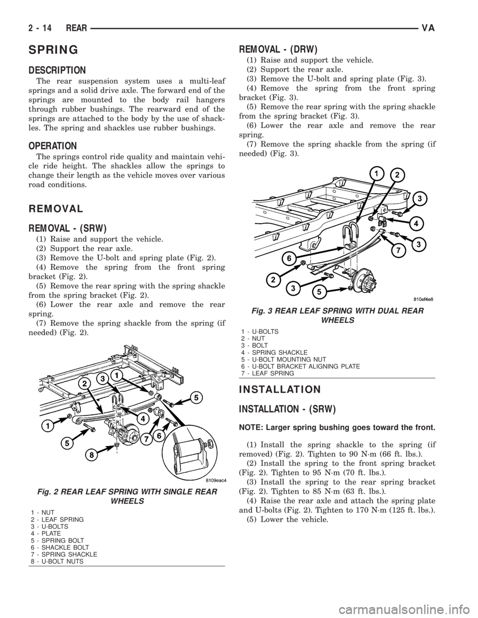
(3) Remove the U-bolt and spring plate (Fig. 2).
(4) Remove the spring from the front spring
bracket (Fig. 2).
(5) Remove the rear spring with the spring shackle
from the spring bracket (Fig. 2).
(6) Lower the rear axle and remove the rear
spring.
(7) Remove the spring shackle from the spring (if
needed) (Fig. 2).
REMOVAL - (DRW)
(1) Raise and support the vehicle.
(2) Support the rear axle.
(3) Remove the U-bolt and spring plate (Fig. 3).
(4) Remove the spring from the front spring
bracket (Fig. 3).
(5) Remove the rear spring with the spring shackle
from the spring bracket (Fig. 3).
(6) Lower the rear axle and remove the rear
spring.
(7) Remove the spring shackle from the spring (if
needed) (Fig. 3).
INSTALLATION
INSTALLATION - (SRW)
NOTE: Larger spring bushing goes toward the front.
(1) Install the spring shackle to the spring (if
removed) (Fig. 2). Tighten to 90 N´m (66 ft. lbs.).
(2) Install the spring to the front spring bracket
(Fig. 2). Tighten to 95 N´m (70 ft. lbs.).
(3) Install the spring to the rear spring bracket
(Fig. 2). Tighten to 85 N´m (63 ft. lbs.).
(4) Raise the rear axle and attach the spring plate
and U-bolts (Fig. 2). Tighten to 170 N´m (125 ft. lbs.).
(5) Lower the vehicle.
Fig. 2 REAR LEAF SPRING WITH SINGLE REAR
WHEELS
1 - NUT
2 - LEAF SPRING
3 - U-BOLTS
4 - PLATE
5 - SPRING BOLT
6 - SHACKLE BOLT
7 - SPRING SHACKLE
8 - U-BOLT NUTS
Fig. 3 REAR LEAF SPRING WITH DUAL REAR
WHEELS
1 - U-BOLTS
2 - NUT
3 - BOLT
4 - SPRING SHACKLE
5 - U-BOLT MOUNTING NUT
6 - U-BOLT BRACKET ALIGNING PLATE
7 - LEAF SPRING
2 - 14 REARVA
Page 740 of 2305
INSTALLATION - (DRW)
NOTE: Larger spring bushing goes toward the front.
(1) Install the spring shackle to the spring (if
removed) (Fig. 3). Tighten to 185 N´m (136 ft. lbs.).
(2) Install the spring to the front spring bracket
(Fig. 3). Tighten to 185 N´m (136 ft. lbs.).
(3) Install the spring to the rear spring bracket
(Fig. 3). Tighten to 185 N´m (136 ft. lbs.).
(4) Raise the rear axle and attach the spring plate
and U-bolts (Fig. 3). Tighten to 170 N´m (125 ft. lbs.).
(5) Lower the vehicle.
SPRING SHACKLE
REMOVAL
(1) Raise and support the vehicle.
(2) Support the rear axle.
(3) Remove both the rear spring shackles from the
spring bracket.
(4) Lower the rear axle and remove the rear spring
shackle from the spring.
INSTALLATION
(1) Install the spring shackle to the spring.
Tighten to 90 N´m (66 ft. lbs.).
(2) Raise the rear axle while installing the spring
shackle to the spring bracket. Tighten to 85 N´m (63
ft. lbs.).
(3) Lower the vehicle.
STABILIZER BAR
REMOVAL
(1) Raise and support the vehicle.
(2) Remove the stabilizer links at the bar (Fig. 4).
(3) Remove the stabilizer bar clamp at the axle
(Fig. 4).
(4) Remove the bracket (Fig. 4)
(5) Remove the stabilizer bar from the vehicle.
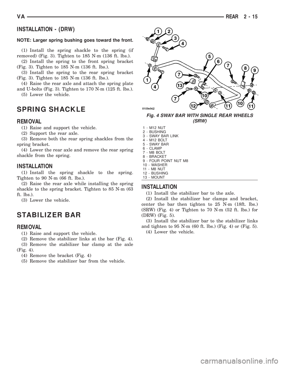
INSTALLATION
(1) Install the stabilizer bar to the axle.
(2) Install the stabilizer bar clamps and bracket,
center the bar then tighten to 25 N´m (18ft. lbs.)
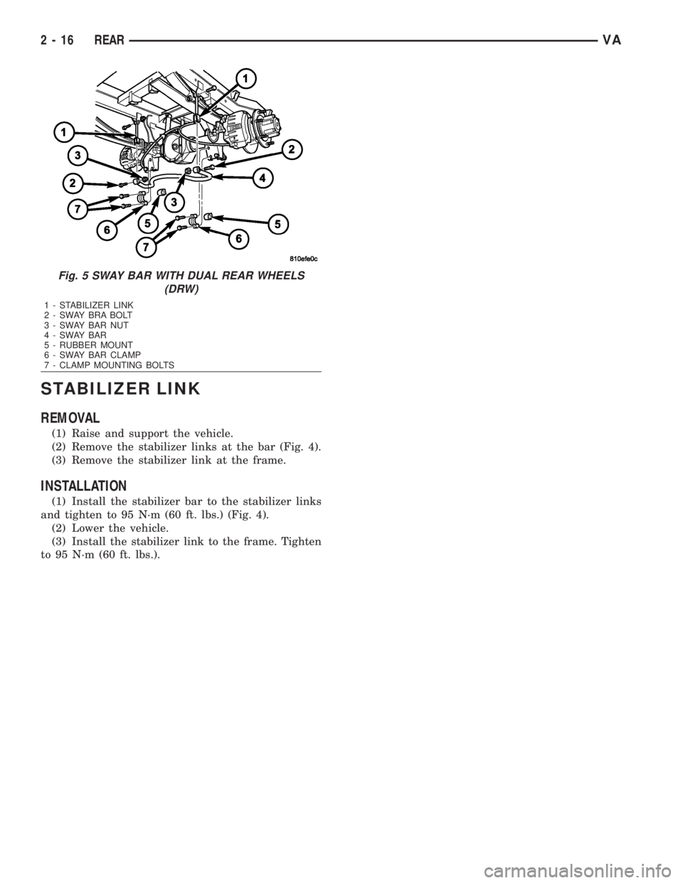
(SRW) (Fig. 4) or Tighten to 70 N´m (52 ft. lbs.) for
(DRW) (Fig. 5).
(3) Install the stabilizer bar to the stabilizer links
and tighten to 95 N´m (60 ft. lbs.) (Fig. 4) or (Fig. 5).
(4) Lower the vehicle.
Fig. 4 SWAY BAR WITH SINGLE REAR WHEELS
(SRW)
1 - M12 NUT
2 - BUSHING
3 - SWAY BAR LINK
4 - M12 BOLT
5-SWAYBAR
6 - CLAMP
7-M8BOLT
8 - BRACKET
9 - FOUR POINT NUT M8
10 - WASHER
11-M8NUT
12 - BUSHING
13 - MOUNT
VAREAR 2 - 15
Page 741 of 2305
STABILIZER LINK
REMOVAL
(1) Raise and support the vehicle.
(2) Remove the stabilizer links at the bar (Fig. 4).
(3) Remove the stabilizer link at the frame.
INSTALLATION
(1) Install the stabilizer bar to the stabilizer links
and tighten to 95 N´m (60 ft. lbs.) (Fig. 4).
(2) Lower the vehicle.
(3) Install the stabilizer link to the frame. Tighten
to 95 N´m (60 ft. lbs.).
Fig. 5 SWAY BAR WITH DUAL REAR WHEELS
(DRW)
1 - STABILIZER LINK
2 - SWAY BRA BOLT
3 - SWAY BAR NUT
4-SWAYBAR
5 - RUBBER MOUNT
6 - SWAY BAR CLAMP
7 - CLAMP MOUNTING BOLTS
2 - 16 REARVA