2006 MERCEDES-BENZ SPRINTER wheel bolts
[x] Cancel search: wheel boltsPage 1939 of 2305
STANDARD PROCEDURE - REPAIRING LEAKS
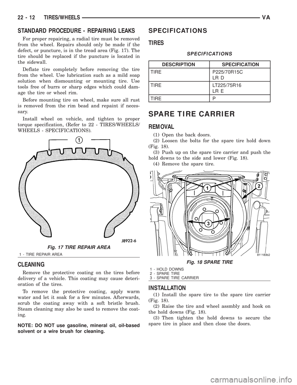
For proper repairing, a radial tire must be removed
from the wheel. Repairs should only be made if the
defect, or puncture, is in the tread area (Fig. 17). The
tire should be replaced if the puncture is located in
the sidewall.
Deflate tire completely before removing the tire
from the wheel. Use lubrication such as a mild soap
solution when dismounting or mounting tire. Use
tools free of burrs or sharp edges which could dam-
age the tire or wheel rim.
Before mounting tire on wheel, make sure all rust
is removed from the rim bead and repaint if neces-
sary.
Install wheel on vehicle, and tighten to proper
torque specification, (Refer to 22 - TIRES/WHEELS/
WHEELS - SPECIFICATIONS).
CLEANING
Remove the protective coating on the tires before
delivery of a vehicle. This coating may cause deteri-
oration of the tires.
To remove the protective coating, apply warm
water and let it soak for a few minutes. Afterwards,
scrub the coating away with a soft bristle brush.
Steam cleaning may also be used to remove the coat-
ing.
NOTE: DO NOT use gasoline, mineral oil, oil-based
solvent or a wire brush for cleaning.
SPECIFICATIONS
TIRES
SPECIFICATIONS
DESCRIPTION SPECIFICATION
TIRE P225/70R15C
LR D
TIRE LT225/75R16
LR E
TIRE P
SPARE TIRE CARRIER
REMOVAL
(1) Open the back doors.
(2) Loosen the bolts for the spare tire hold down
(Fig. 18).
(3) Push up on the spare tire carrier and push the
hold downs to the side and lower (Fig. 18).
(4) Remove the spare tire.
INSTALLATION
(1) Install the spare tire to the spare tire carrier
(Fig. 18).
(2) Raise the tire and wheel assmbly and hook on
the hold downs (Fig. 18).
(3) Then tighten the hold downs to secure the
spare tire in place and then close the doors.
Fig. 17 TIRE REPAIR AREA
1 - TIRE REPAIR AREA
Fig. 18 SPARE TIRE
1 - HOLD DOWNS
2 - SPARE TIRE
3 - SPARE TIRE CARRIER
22 - 12 TIRES/WHEELSVA
Page 1996 of 2305
PROP ROD
REMOVAL
(1) Open and support hood.
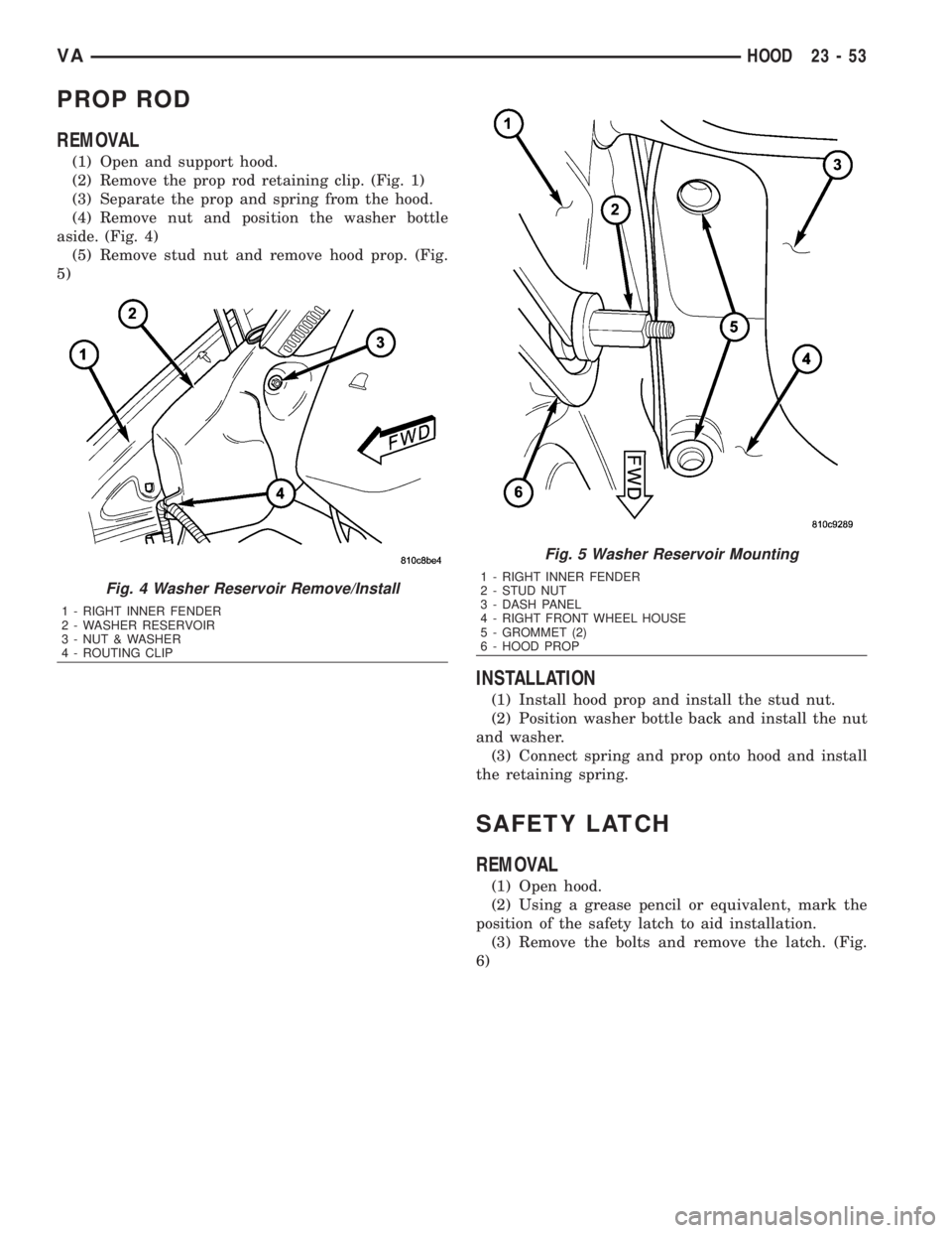
(2) Remove the prop rod retaining clip. (Fig. 1)
(3) Separate the prop and spring from the hood.
(4) Remove nut and position the washer bottle
aside. (Fig. 4)
(5) Remove stud nut and remove hood prop. (Fig.
5)
INSTALLATION
(1) Install hood prop and install the stud nut.
(2) Position washer bottle back and install the nut
and washer.
(3) Connect spring and prop onto hood and install
the retaining spring.
SAFETY LATCH
REMOVAL
(1) Open hood.
(2) Using a grease pencil or equivalent, mark the
position of the safety latch to aid installation.
(3) Remove the bolts and remove the latch. (Fig.
6)
Fig. 4 Washer Reservoir Remove/Install
1 - RIGHT INNER FENDER
2 - WASHER RESERVOIR
3 - NUT & WASHER
4 - ROUTING CLIP
Fig. 5 Washer Reservoir Mounting
1 - RIGHT INNER FENDER
2 - STUD NUT
3 - DASH PANEL
4 - RIGHT FRONT WHEEL HOUSE
5 - GROMMET (2)
6 - HOOD PROP
VAHOOD 23 - 53
Page 2001 of 2305
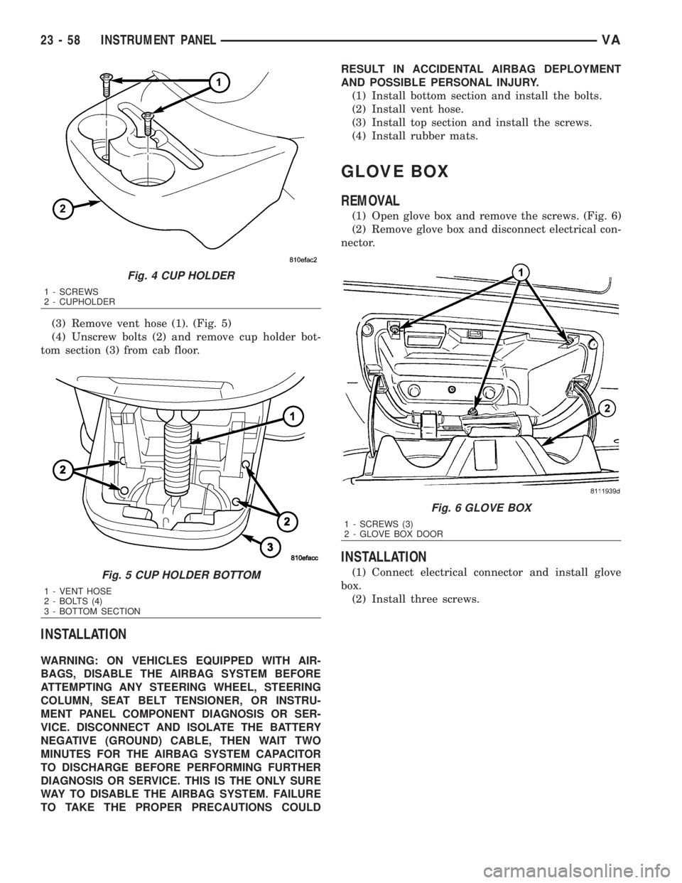
(3) Remove vent hose (1). (Fig. 5)
(4) Unscrew bolts (2) and remove cup holder bot-
tom section (3) from cab floor.
INSTALLATION
WARNING: ON VEHICLES EQUIPPED WITH AIR-
BAGS, DISABLE THE AIRBAG SYSTEM BEFORE
ATTEMPTING ANY STEERING WHEEL, STEERING
COLUMN, SEAT BELT TENSIONER, OR INSTRU-
MENT PANEL COMPONENT DIAGNOSIS OR SER-
VICE. DISCONNECT AND ISOLATE THE BATTERY
NEGATIVE (GROUND) CABLE, THEN WAIT TWO
MINUTES FOR THE AIRBAG SYSTEM CAPACITOR
TO DISCHARGE BEFORE PERFORMING FURTHER
DIAGNOSIS OR SERVICE. THIS IS THE ONLY SURE
WAY TO DISABLE THE AIRBAG SYSTEM. FAILURE
TO TAKE THE PROPER PRECAUTIONS COULDRESULT IN ACCIDENTAL AIRBAG DEPLOYMENT
AND POSSIBLE PERSONAL INJURY.
(1) Install bottom section and install the bolts.
(2) Install vent hose.
(3) Install top section and install the screws.
(4) Install rubber mats.
GLOVE BOX
REMOVAL
(1) Open glove box and remove the screws. (Fig. 6)
(2) Remove glove box and disconnect electrical con-
nector.
INSTALLATION
(1) Connect electrical connector and install glove
box.
(2) Install three screws.
Fig. 4 CUP HOLDER
1 - SCREWS
2 - CUPHOLDER
Fig. 5 CUP HOLDER BOTTOM
1 - VENT HOSE
2 - BOLTS (4)
3 - BOTTOM SECTION
Fig. 6 GLOVE BOX
1 - SCREWS (3)
2 - GLOVE BOX DOOR
23 - 58 INSTRUMENT PANELVA
Page 2005 of 2305
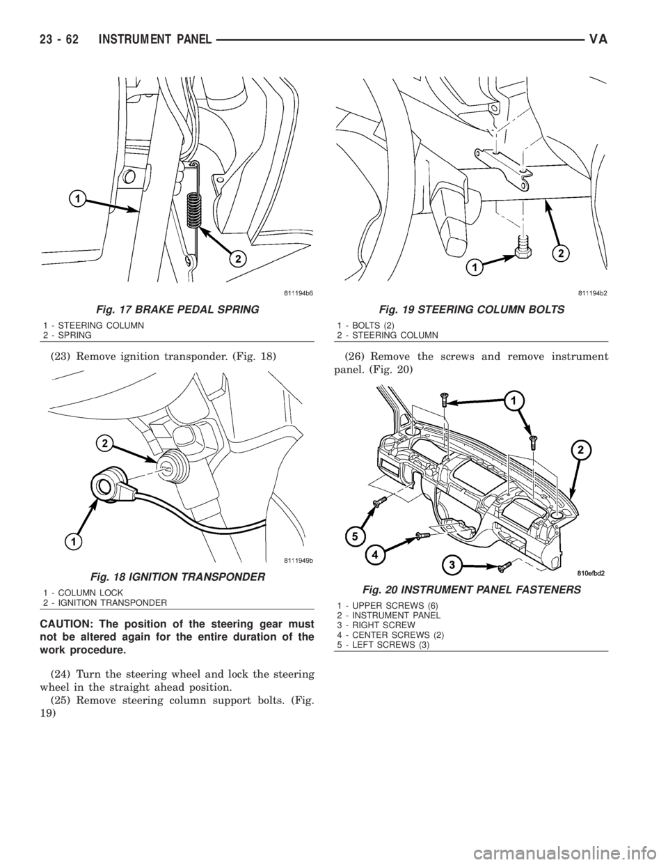
(23) Remove ignition transponder. (Fig. 18)
CAUTION: The position of the steering gear must
not be altered again for the entire duration of the
work procedure.
(24) Turn the steering wheel and lock the steering
wheel in the straight ahead position.
(25) Remove steering column support bolts. (Fig.
19)(26) Remove the screws and remove instrument
panel. (Fig. 20)
Fig. 17 BRAKE PEDAL SPRING
1 - STEERING COLUMN
2 - SPRING
Fig. 18 IGNITION TRANSPONDER
1 - COLUMN LOCK
2 - IGNITION TRANSPONDER
Fig. 19 STEERING COLUMN BOLTS
1 - BOLTS (2)
2 - STEERING COLUMN
Fig. 20 INSTRUMENT PANEL FASTENERS
1 - UPPER SCREWS (6)
2 - INSTRUMENT PANEL
3 - RIGHT SCREW
4 - CENTER SCREWS (2)
5 - LEFT SCREWS (3)
23 - 62 INSTRUMENT PANELVA
Page 2006 of 2305
INSTALLATION
WARNING: ON VEHICLES EQUIPPED WITH AIR-
BAGS, DISABLE THE AIRBAG SYSTEM BEFORE
ATTEMPTING ANY STEERING WHEEL, STEERING
COLUMN, SEAT BELT TENSIONER, OR INSTRU-
MENT PANEL COMPONENT DIAGNOSIS OR SER-
VICE. DISCONNECT AND ISOLATE THE BATTERY
NEGATIVE (GROUND) CABLE, THEN WAIT TWO
MINUTES FOR THE AIRBAG SYSTEM CAPACITOR
TO DISCHARGE BEFORE PERFORMING FURTHER
DIAGNOSIS OR SERVICE. THIS IS THE ONLY SURE
WAY TO DISABLE THE AIRBAG SYSTEM. FAILURE
TO TAKE THE PROPER PRECAUTIONS COULD
RESULT IN ACCIDENTAL AIRBAG DEPLOYMENT
AND POSSIBLE PERSONAL INJURY.
²WHEN REMOVING A DEPLOYED AIRBAG, RUB-
BER GLOVES, EYE PROTECTION, AND A LONG-
SLEEVED SHIRT SHOULD BE WORN. THERE MAY
BE DEPOSITS ON THE AIRBAG UNIT AND OTHER
INTERIOR SURFACES. IN LARGE DOSES, THESE
DEPOSITS MAY CAUSE IRRITATION TO THE SKIN
AND EYES.
²USE EXTREME CARE TO PREVENT ANY FOR-
EIGN MATERIAL FROM ENTERING THE PASSEN-
GER AIRBAG, OR BECOMING ENTRAPPED
BETWEEN THE PASSENGER AIRBAG CUSHION
AND THE PASSENGER AIRBAG DOOR. FAILURE TO
OBSERVE THIS WARNING COULD RESULT IN
OCCUPANT INJURIES UPON AIRBAG DEPLOY-
MENT.
²THE PASSENGER AIRBAG DOOR MUST
NEVER BE PAINTED. REPLACEMENT PASSENGER
AIRBAGS ARE SERVICED WITH DOORS IN THE
ORIGINAL COLORS. PAINT MAY CHANGE THE WAY
IN WHICH THE MATERIAL OF THE AIRBAG DOOR
RESPONDS TO AN AIRBAG DEPLOYMENT. FAIL-
URE TO OBSERVE THIS WARNING COULD RESULT
IN OCCUPANT INJURIES UPON AIRBAG DEPLOY-
MENT.
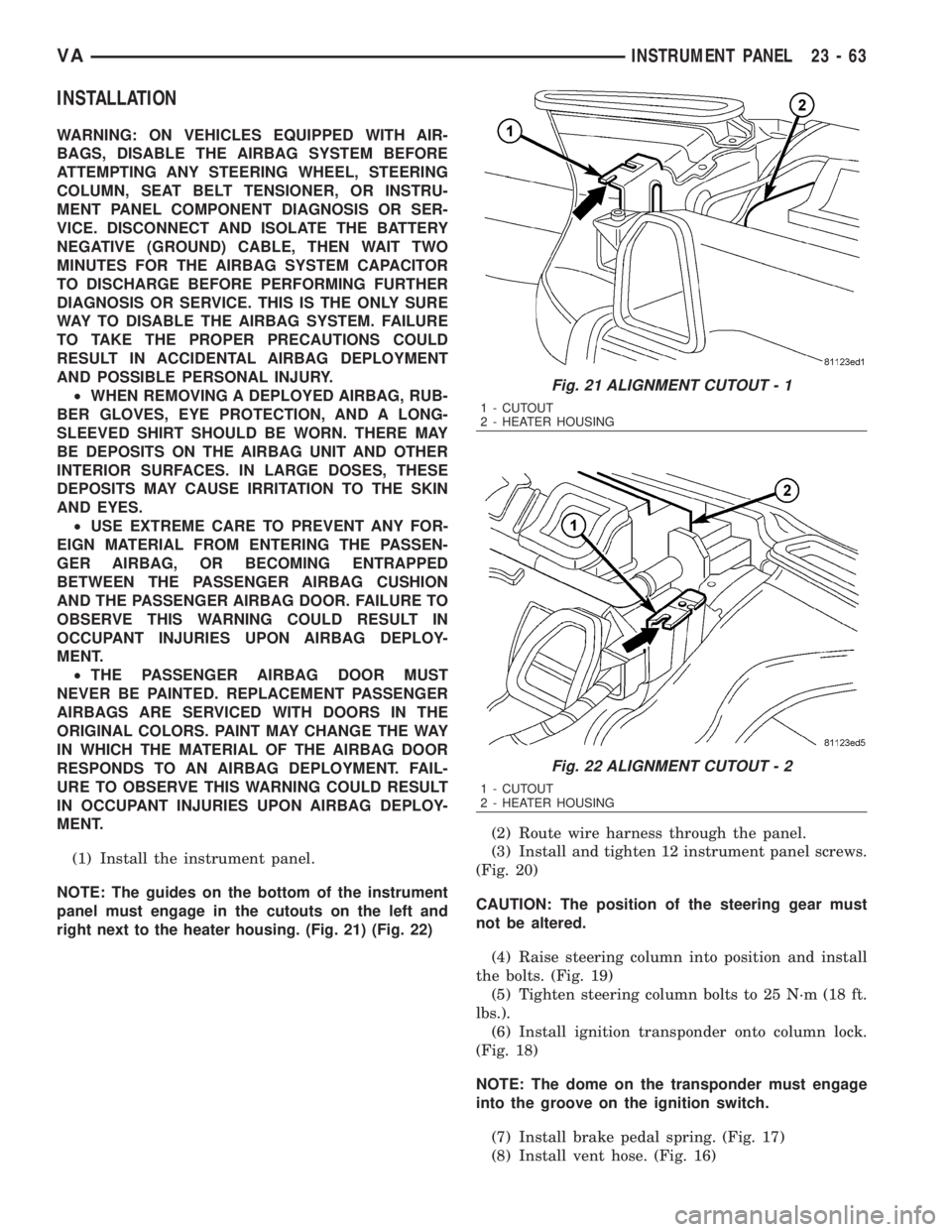
(1) Install the instrument panel.
NOTE: The guides on the bottom of the instrument
panel must engage in the cutouts on the left and
right next to the heater housing. (Fig. 21) (Fig. 22)(2) Route wire harness through the panel.
(3) Install and tighten 12 instrument panel screws.
(Fig. 20)
CAUTION: The position of the steering gear must
not be altered.
(4) Raise steering column into position and install
the bolts. (Fig. 19)
(5) Tighten steering column bolts to 25 N´m (18 ft.
lbs.).
(6) Install ignition transponder onto column lock.
(Fig. 18)
NOTE: The dome on the transponder must engage
into the groove on the ignition switch.
(7) Install brake pedal spring. (Fig. 17)
(8) Install vent hose. (Fig. 16)
Fig. 21 ALIGNMENT CUTOUT - 1
1 - CUTOUT
2 - HEATER HOUSING
Fig. 22 ALIGNMENT CUTOUT - 2
1 - CUTOUT
2 - HEATER HOUSING
VAINSTRUMENT PANEL 23 - 63
Page 2113 of 2305
INSTALLATION
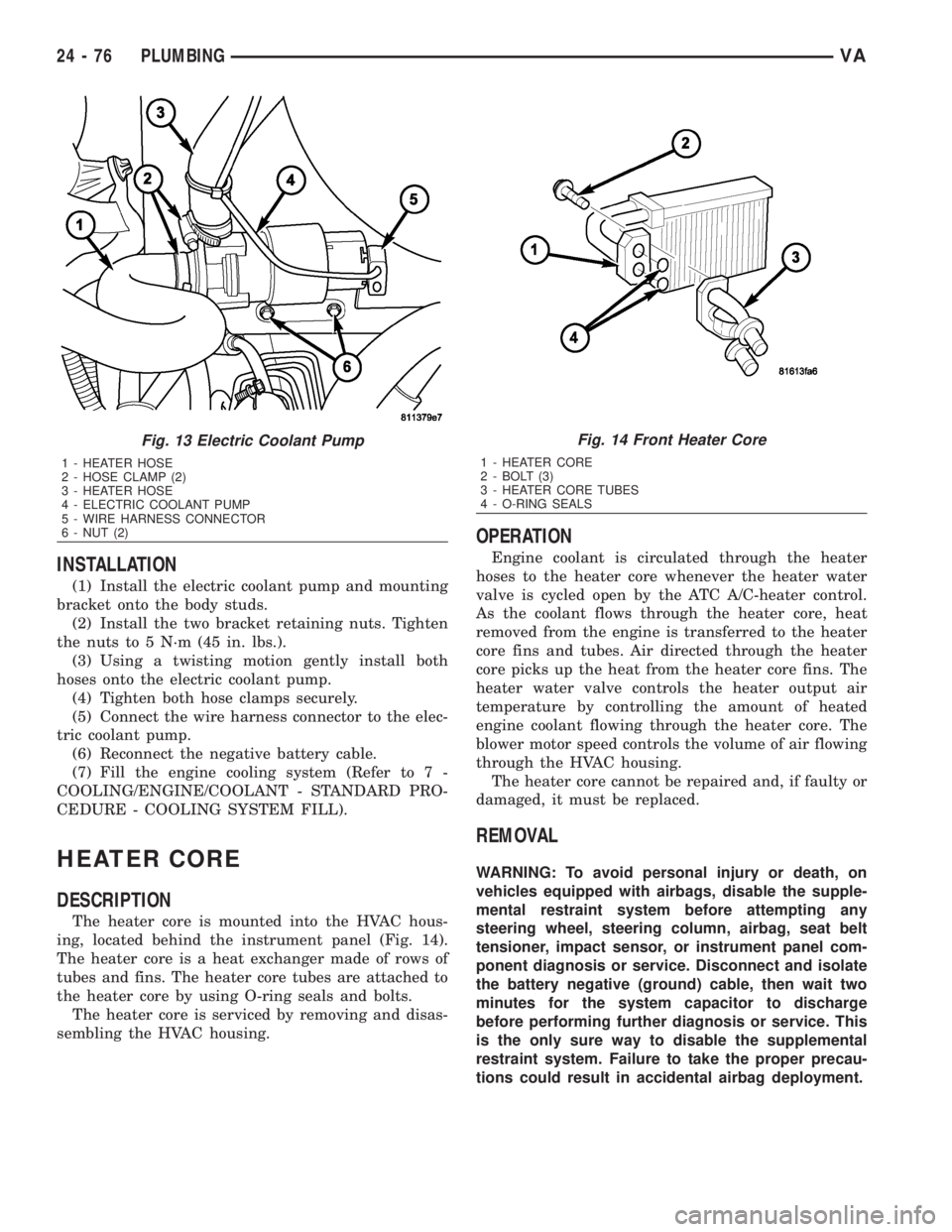
(1) Install the electric coolant pump and mounting
bracket onto the body studs.
(2) Install the two bracket retaining nuts. Tighten
the nuts to 5 N´m (45 in. lbs.).
(3) Using a twisting motion gently install both
hoses onto the electric coolant pump.
(4) Tighten both hose clamps securely.
(5) Connect the wire harness connector to the elec-
tric coolant pump.
(6) Reconnect the negative battery cable.
(7) Fill the engine cooling system (Refer to 7 -
COOLING/ENGINE/COOLANT - STANDARD PRO-
CEDURE - COOLING SYSTEM FILL).
HEATER CORE
DESCRIPTION
The heater core is mounted into the HVAC hous-
ing, located behind the instrument panel (Fig. 14).
The heater core is a heat exchanger made of rows of
tubes and fins. The heater core tubes are attached to
the heater core by using O-ring seals and bolts.
The heater core is serviced by removing and disas-
sembling the HVAC housing.
OPERATION
Engine coolant is circulated through the heater
hoses to the heater core whenever the heater water
valve is cycled open by the ATC A/C-heater control.
As the coolant flows through the heater core, heat
removed from the engine is transferred to the heater
core fins and tubes. Air directed through the heater
core picks up the heat from the heater core fins. The
heater water valve controls the heater output air
temperature by controlling the amount of heated
engine coolant flowing through the heater core. The
blower motor speed controls the volume of air flowing
through the HVAC housing.
The heater core cannot be repaired and, if faulty or
damaged, it must be replaced.
REMOVAL
WARNING: To avoid personal injury or death, on
vehicles equipped with airbags, disable the supple-
mental restraint system before attempting any
steering wheel, steering column, airbag, seat belt
tensioner, impact sensor, or instrument panel com-
ponent diagnosis or service. Disconnect and isolate
the battery negative (ground) cable, then wait two
minutes for the system capacitor to discharge
before performing further diagnosis or service. This
is the only sure way to disable the supplemental
restraint system. Failure to take the proper precau-
tions could result in accidental airbag deployment.
Fig. 13 Electric Coolant Pump
1 - HEATER HOSE
2 - HOSE CLAMP (2)
3 - HEATER HOSE
4 - ELECTRIC COOLANT PUMP
5 - WIRE HARNESS CONNECTOR
6 - NUT (2)
Fig. 14 Front Heater Core
1 - HEATER CORE
2 - BOLT (3)
3 - HEATER CORE TUBES
4 - O-RING SEALS
24 - 76 PLUMBINGVA