2006 MERCEDES-BENZ SPRINTER remove seats
[x] Cancel search: remove seatsPage 912 of 2305

The heated seat system components operate on
battery current received through a fuse in the Fuse
Block on a fused ignition switch output (run-acc) cir-
cuit so that the system will only operate when the
ignition switch is in the On or Accessory positions.
The heated seat system will be turned Off automati-
cally whenever the ignition switch is turned to any
position except On or Accessory. Also, the heated seat
system will not operate when the surface tempera-
ture of the seat cushion cover at either heated seat
sensor is above the designed temperature set points
of the system.DIAGNOSIS AND TESTING - HEATED SEATS
Refer toWiringfor the appropriate wiring infor-
mation. The wiring information includes wiring dia-
grams, proper wire and connector repair procedures,
further details on wire harness routing and reten-
tion, as well as pin-out and location views for the
various wire harness connectors, splices and grounds.
HEATED SEAT SYSTEM DIAGNOSIS
CONDITION POSSIBLE CAUSES CORRECTION
NO HEATED SEAT SWITCH
ILLUMINATION WITH IGNI-
TION ON1. Faulty fuse. 1. Check heated seat fuse in Fuse Block. Re-
place fuse, if required.
2. Wiring faulty. 2. Check fused ignition switch output (run-acc)
circuit from heated seat switch connector to igni-
tion switch. Repair, if required.
3. Ground faulty. 3. Check for ground at heated seat switch con-
nector. Repair, if required.
4. Faulty switch. 4. Refer to Heated Seat Switch for the proper
switch diagnosis and testing procedures.
DRIVER HEATED SEAT
SWITCH
DESCRIPTION
The heated seat switches are located on the instru-
ment panel, in the accessory switch bezel. The two,
momentary rocker type switches provide a signal to
the Heated Seat Relay through separate hard wired
circuits. Each switch contains two light emitting
diodes (LED), one for each High and Low setting to
let the occupant know that the seat heater system is
on.
The heated seat switches and their LED's cannot
be repaired. If either switch is faulty or damaged the
entire switch must be replaced.
OPERATION
There are three modes that can be selected with
each of the heated seat switches: Off, Low, and High.
When the top of the switch rocker is depressed, the
low mode is selected and the low mode LED indicator
illuminates. Depressing the top of the switch rocker a
second time will turn the heated seat to Off. This
same process is repeated for High heat setting. The
heated seats will automatically return to the Off
mode anytime the vehicle ignition switch is turned
Off.Both switches provide separate hard wire inputs to
the Heated Seat Relay to indicate the selected mode.
The Heated Seat Relay responds to the heated seat
switch messages by controlling the output to the seat
heater elements of the selected seat.
DIAGNOSIS AND TESTING - DRIVER HEATED
SEAT SWITCH
For circuit description and diagrams, refer toWir-
ing.
(1) Inspect the Heated Seat Switches for apparent
damage or sticking/binding and replace if required.
Refer to Heated Seat Switch Removal and Installa-
tion in this section.
(2) Replace the heated seat switch with a known
good unit and retest the heated seat system.
REMOVAL
(1) Disconnect and isolate the negative battery
cable.
(2) Remove the gear selector bezel trim. Refer to
the Body section for the procedure.
(3) Remove the storage bin. Refer to the Body sec-
tion for the procedure.
(4) Remove the switch bezel retaining screw and
remove the switch bezel from the instrument panel.
Refer to the Body section for the procedure.
(5) Disconnect electrical connections.
VAHEATED SEATS 8G - 11
Page 914 of 2305

The heated seat relay cannot be repaired or
adjusted and, if faulty or damaged, it must be
replaced.
OPERATION
The ISO relay consists of an electromagnetic coil, a
resistor or diode, and three (two fixed and one mov-
able) electrical contacts. The movable (common feed)
relay contact is held against one of the fixed contacts
(normally closed) by spring pressure. When the elec-
tromagnetic coil is energized, it draws the movable
contact away from the normally closed fixed contact,
and holds it against the other (normally open) fixed
contact. When the electromagnetic coil is de-ener-
gized, spring pressure returns the movable contact to
the normally closed position. The resistor or diode is
connected in parallel with the electromagnetic coil in
the relay, and helps to dissipate voltage spikes that
are produced when the coil is de-energized.
DIAGNOSIS AND TESTING - HEATED SEAT
RELAY
The heated seat relay is located in the Fuse Block,
under the drivers seat. Refer toWiringfor the loca-
tion of complete heated seat system wiring diagrams.
(1) Remove the heated seat relay from the fuse
block.
(2) A relay in the de-energized position should
have continuity between terminals 87A and 30, and
no continuity between terminals 87 and 30. If OK, go
to Step 3. If not OK, replace the faulty relay.
(3) Resistance between terminals 85 and 86 (elec-
tromagnet) should be 75 5 ohms. If OK, go to Step
4. If not OK, replace the faulty relay.
(4) Connect a battery to terminals 85 and 86.
There should now be continuity between terminals
30 and 87, and no continuity between terminals 87A
and 30. If OK, check the relay supply circuits. If not
OK, replace the faulty relay.
REMOVAL
(1) Disconnect and isolate the battery negative
cable.
(2) The heated seat relay is located in the fuse
block, under the drivers seat. Refer to wiring for
detailed location.
(3) Grasp the heated seat relay firmly and pull it
straight out from the fuse block. A slight rocking
motion will aid in removal.
INSTALLATION
(1) Grasp the heated seat relay firmly and push it
straight in the fuse block.
(2) Reconnect the battery negative cable.
HEATED SEAT SENSOR
DESCRIPTION
The heated seat temperature sensor is a Negative
Temperature Coefficient (NTC) thermistor. One tem-
perature sensor is used for each seat. The sensor is
located in the seat cushion heating element for all
models.
The heated seat sensor cannot be adjusted or
repaired and if it is found to be faulty, the complete
heated seat element must be replaced.
DIAGNOSIS AND TESTING - HEATED SEAT
SENSOR
For complete circuit diagrams, refer toWiring.
NOTE: Any resistance values (ohmsV) given in the
following text are supplied using the automatic
range generated by a FLUKETautomotive meter. If
another type of measuring device is used the val-
ues generated may not be the same as the results
shown here, or may have to be converted to the
range used here.
(1) Backprobe the heated seat relay wire harness
connector, do not disconnect. Using an voltmeter,
check the voltage of the seat temperature sensor
input cavity of the heated seat relay wire harness
connector. The seat sensor input voltage should be
between 1.7 volts and 3.0 volts with the system ON.
If OK, sensor is OK at this time. If not OK, replace
the faulty seat cushion heating element and sensor
assembly.
PASSENGER HEATED SEAT
SWITCH
DESCRIPTION
The heated seat switches are located on the instru-
ment panel, in the accessory switch bezel. The two,
momentary rocker type switches provide a signal to
the Heated Seat Relay through separate hard wired
circuits. Each switch contains two light emitting
diodes (LED), one for each High and Low setting to
let the occupant know that the seat heater system is
on.
The heated seat switches and their LED's cannot
be repaired. If either switch is faulty or damaged the
entire switch must be replaced.
OPERATION
There are three modes that can be selected with
each of the heated seat switches: Off, Low, and High.
When the top of the switch rocker is depressed, the
low mode is selected and the low mode LED indicator
illuminates. Depressing the top of the switch rocker a
VAHEATED SEATS 8G - 13
Page 915 of 2305
second time will turn the heated seat to Off. This
same process is repeated for High heat setting. The
heated seats will automatically return to the Off
mode anytime the vehicle ignition switch is turned
Off.
Both switches provide separate hard wire inputs to
the Heated Seat Relay to indicate the selected mode.
The Heated Seat Relay responds to the heated seat
switch messages by controlling the output to the seat
heater elements of the selected seat.
DIAGNOSIS AND TESTING - PASSENGER
HEATED SEAT SWITCH
For circuit description and diagrams, refer toWir-
ing.
(1) Inspect the Heated Seat Switches for apparent
damage or sticking/binding and replace if required.
Refer to Heated Seat Switch Removal and Installa-
tion in this section.
(2) Replace the heated seat switch with a known
good unit and retest the heated seat system.
REMOVAL
(1) Disconnect and isolate the negative battery
cable.
(2) Remove the gear selector bezel trim. Refer to
the Body section for the procedure.
(3) Remove the storage bin. Refer to the Body sec-
tion for the procedure.
(4) Remove the switch bezel retaining screw and
remove the switch bezel from the instrument panel.
Refer to the Body section for the procedure.
(5) Disconnect electrical connections.
(6) Working from the underside of the switch, gen-
tly rock the switch back and forth out of its mounting
location in the switch bezel.
INSTALLATION
(1) Install the heated seat switch in its mounting
location in the switch bezel.
(2) Connect electrical connections.
(3) Position the switch bezel and install the retain-
ing screw. Refer to the Body section for the proce-
dure.
(4) Install the storage bin. Refer to the Body sec-
tion for the procedure.
(5) Install the gear selector bezel trim. Refer to the
Body section for the procedure.
(6) Connect the negative battery cable.
8G - 14 HEATED SEATSVA
Page 1020 of 2305
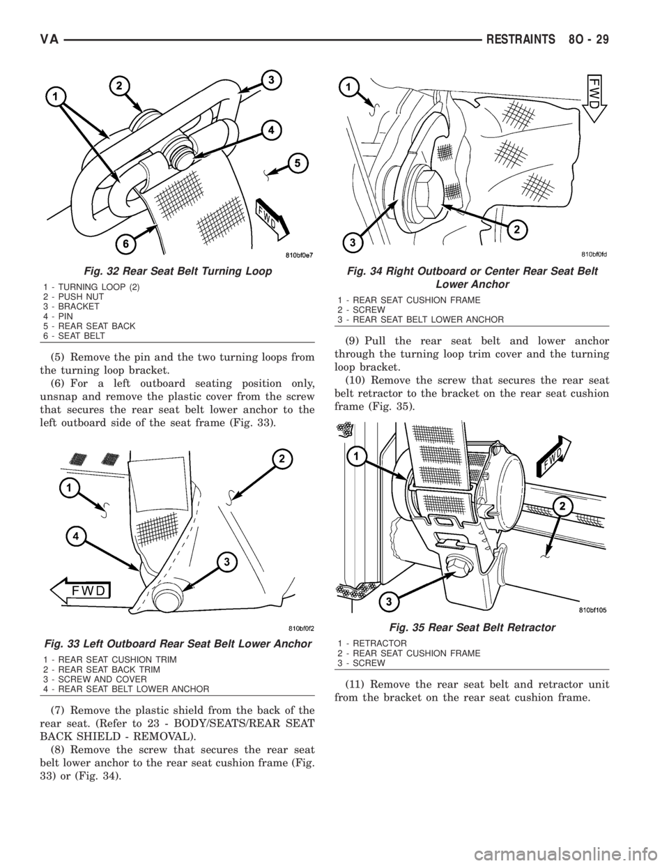
(5) Remove the pin and the two turning loops from
the turning loop bracket.
(6) For a left outboard seating position only,
unsnap and remove the plastic cover from the screw
that secures the rear seat belt lower anchor to the
left outboard side of the seat frame (Fig. 33).
(7) Remove the plastic shield from the back of the
rear seat. (Refer to 23 - BODY/SEATS/REAR SEAT
BACK SHIELD - REMOVAL).
(8) Remove the screw that secures the rear seat
belt lower anchor to the rear seat cushion frame (Fig.
33) or (Fig. 34).(9) Pull the rear seat belt and lower anchor
through the turning loop trim cover and the turning
loop bracket.
(10) Remove the screw that secures the rear seat
belt retractor to the bracket on the rear seat cushion
frame (Fig. 35).
(11) Remove the rear seat belt and retractor unit
from the bracket on the rear seat cushion frame.
Fig. 32 Rear Seat Belt Turning Loop
1 - TURNING LOOP (2)
2 - PUSH NUT
3 - BRACKET
4 - PIN
5 - REAR SEAT BACK
6 - SEAT BELT
Fig. 33 Left Outboard Rear Seat Belt Lower Anchor
1 - REAR SEAT CUSHION TRIM
2 - REAR SEAT BACK TRIM
3 - SCREW AND COVER
4 - REAR SEAT BELT LOWER ANCHOR
Fig. 34 Right Outboard or Center Rear Seat Belt
Lower Anchor
1 - REAR SEAT CUSHION FRAME
2 - SCREW
3 - REAR SEAT BELT LOWER ANCHOR
Fig. 35 Rear Seat Belt Retractor
1 - RETRACTOR
2 - REAR SEAT CUSHION FRAME
3 - SCREW
VARESTRAINTS 8O - 29
Page 1021 of 2305
INSTALLATION
WARNING: To avoid personal injury or death, during
and following any seat belt service, carefully
inspect all seat belts, buckles, mounting hardware,
retractors, and anchors for proper installation, oper-
ation, or damage. Replace any belt that is cut,
frayed, or torn. Straighten any belt that is twisted.
Tighten any loose fasteners. Replace any belt that
has a damaged or inoperative buckle or retractor.
Replace any belt that has a bent or damaged latch
plate or anchor plate. Never attempt to repair a seat
belt component. Always replace damaged or faulty
seat belt components with the correct, new and
unused replacement parts listed in the
DaimlerChrysler Mopar Parts Catalog.
(1) Position the rear seat belt and retractor unit
onto the bracket of the rear seat cushion frame (Fig.
35). Be certain to engage the guide on the retractor
into the locating notch on the bracket.
(2) Install and tighten the screw that secures the
rear seat belt retractor to the bracket on the rear
seat cushion frame. Tighten the screw to 35 N´m (26
ft. lbs.).
(3) Route the rear seat belt and lower anchor
through the turning loop bracket and the turning
loop trim cover.
(4) Position the rear seat belt lower anchor to the
rear seat cushion frame (Fig. 33) or (Fig. 34).
(5) Install and tighten the screw that secures the
rear seat belt lower anchor to the rear seat cushion
frame. Tighten the screw to 35 N´m (26 ft. lbs.).
(6) For a left outboard seating position only, rein-
stall the plastic cover onto the screw that secures the
rear seat belt lower anchor to the left outboard side
of the seat frame.
(7) Position the two seat belt turning loops to the
turning loop bracket so that one turning loop is
located behind the bracket and one is located in front
of the bracket (Fig. 32).
(8) From the front of the turning loop bracket,
insert the pin through both turning loops and the
bracket, then secure it from behind the bracket with
a new push nut.
(9) Position the turning loop trim cover over the
turning loop bracket.
(10) Lift the seat belt webbing to access and install
the plastic push pin fastener that secures the rear
seat belt turning loop trim cover to the turning loop
bracket at the top of the seat back (Fig. 31).
(11) Reinstall the plastic shield onto the back of
the rear seat. (Refer to 23 - BODY/SEATS/REAR
SEAT BACK SHIELD - INSTALLATION).
(12) Reinstall the rear bench seat into the vehicle.
REAR SEAT BELT BUCKLE
REMOVAL
REMOVAL - INBOARD
WARNING: To avoid personal injury or death, during
and following any seat belt service, carefully
inspect all seat belts, buckles, mounting hardware,
retractors, and anchors for proper installation, oper-
ation, or damage. Replace any belt that is cut,
frayed, or torn. Straighten any belt that is twisted.
Tighten any loose fasteners. Replace any belt that
has a damaged or inoperative buckle or retractor.
Replace any belt that has a bent or damaged latch
plate or anchor plate. Never attempt to repair a seat
belt component. Always replace damaged or faulty
seat belt components with the correct, new and
unused replacement parts listed in the
DaimlerChrysler Mopar Parts Catalog.
(1) Remove the rear bench seat containing the
inboard rear seat belt buckle unit to be serviced from
the vehicle.
(2) Remove the plastic shield from the back of the
rear seat. (Refer to 23 - BODY/SEATS/REAR SEAT
BACK SHIELD - REMOVAL).
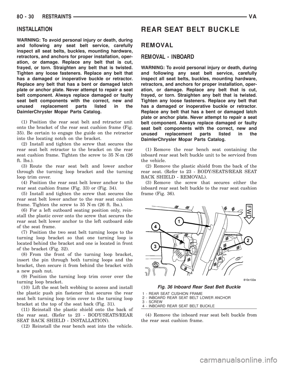
(3) Remove the screw that secures either the
inboard rear seat belt buckle to the rear seat cushion
frame (Fig. 36).
(4) Remove the inboard rear seat belt buckle from
the rear seat cushion frame.
Fig. 36 Inboard Rear Seat Belt Buckle
1 - REAR SEAT CUSHION FRAME
2 - INBOARD REAR SEAT BELT LOWER ANCHOR
3 - SCREW
4 - INBOARD REAR SEAT BELT BUCKLE
8O - 30 RESTRAINTSVA
Page 1022 of 2305
REMOVAL - OUTBOARD
WARNING: To avoid personal injury or death, during
and following any seat belt service, carefully
inspect all seat belts, buckles, mounting hardware,
retractors, and anchors for proper installation, oper-
ation, or damage. Replace any belt that is cut,
frayed, or torn. Straighten any belt that is twisted.
Tighten any loose fasteners. Replace any belt that
has a damaged or inoperative buckle or retractor.
Replace any belt that has a bent or damaged latch
plate or anchor plate. Never attempt to repair a seat
belt component. Always replace damaged or faulty
seat belt components with the correct, new and
unused replacement parts listed in the
DaimlerChrysler Mopar Parts Catalog.
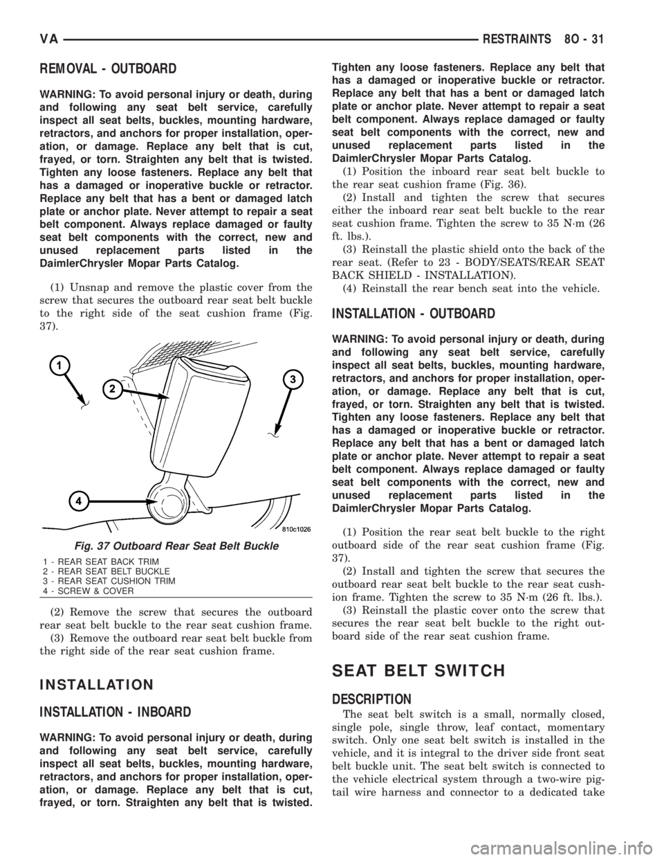
(1) Unsnap and remove the plastic cover from the
screw that secures the outboard rear seat belt buckle
to the right side of the seat cushion frame (Fig.
37).
(2) Remove the screw that secures the outboard
rear seat belt buckle to the rear seat cushion frame.
(3) Remove the outboard rear seat belt buckle from
the right side of the rear seat cushion frame.
INSTALLATION
INSTALLATION - INBOARD
WARNING: To avoid personal injury or death, during
and following any seat belt service, carefully
inspect all seat belts, buckles, mounting hardware,
retractors, and anchors for proper installation, oper-
ation, or damage. Replace any belt that is cut,
frayed, or torn. Straighten any belt that is twisted.Tighten any loose fasteners. Replace any belt that
has a damaged or inoperative buckle or retractor.
Replace any belt that has a bent or damaged latch
plate or anchor plate. Never attempt to repair a seat
belt component. Always replace damaged or faulty
seat belt components with the correct, new and
unused replacement parts listed in the
DaimlerChrysler Mopar Parts Catalog.
(1) Position the inboard rear seat belt buckle to
the rear seat cushion frame (Fig. 36).
(2) Install and tighten the screw that secures
either the inboard rear seat belt buckle to the rear
seat cushion frame. Tighten the screw to 35 N´m (26
ft. lbs.).
(3) Reinstall the plastic shield onto the back of the
rear seat. (Refer to 23 - BODY/SEATS/REAR SEAT
BACK SHIELD - INSTALLATION).
(4) Reinstall the rear bench seat into the vehicle.
INSTALLATION - OUTBOARD
WARNING: To avoid personal injury or death, during
and following any seat belt service, carefully
inspect all seat belts, buckles, mounting hardware,
retractors, and anchors for proper installation, oper-
ation, or damage. Replace any belt that is cut,
frayed, or torn. Straighten any belt that is twisted.
Tighten any loose fasteners. Replace any belt that
has a damaged or inoperative buckle or retractor.
Replace any belt that has a bent or damaged latch
plate or anchor plate. Never attempt to repair a seat
belt component. Always replace damaged or faulty
seat belt components with the correct, new and
unused replacement parts listed in the
DaimlerChrysler Mopar Parts Catalog.
(1) Position the rear seat belt buckle to the right
outboard side of the rear seat cushion frame (Fig.
37).
(2) Install and tighten the screw that secures the
outboard rear seat belt buckle to the rear seat cush-
ion frame. Tighten the screw to 35 N´m (26 ft. lbs.).
(3) Reinstall the plastic cover onto the screw that
secures the rear seat belt buckle to the right out-
board side of the rear seat cushion frame.
SEAT BELT SWITCH
DESCRIPTION
The seat belt switch is a small, normally closed,
single pole, single throw, leaf contact, momentary
switch. Only one seat belt switch is installed in the
vehicle, and it is integral to the driver side front seat
belt buckle unit. The seat belt switch is connected to
the vehicle electrical system through a two-wire pig-
tail wire harness and connector to a dedicated take
Fig. 37 Outboard Rear Seat Belt Buckle
1 - REAR SEAT BACK TRIM
2 - REAR SEAT BELT BUCKLE
3 - REAR SEAT CUSHION TRIM
4 - SCREW & COVER
VARESTRAINTS 8O - 31
Page 1054 of 2305
CHECK VALVE
DESCRIPTION
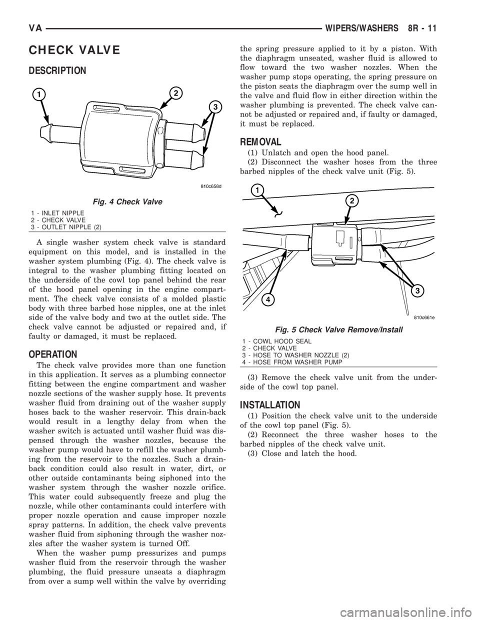
A single washer system check valve is standard
equipment on this model, and is installed in the
washer system plumbing (Fig. 4). The check valve is
integral to the washer plumbing fitting located on
the underside of the cowl top panel behind the rear
of the hood panel opening in the engine compart-
ment. The check valve consists of a molded plastic
body with three barbed hose nipples, one at the inlet
side of the valve body and two at the outlet side. The
check valve cannot be adjusted or repaired and, if
faulty or damaged, it must be replaced.
OPERATION
The check valve provides more than one function
in this application. It serves as a plumbing connector
fitting between the engine compartment and washer
nozzle sections of the washer supply hose. It prevents
washer fluid from draining out of the washer supply
hoses back to the washer reservoir. This drain-back
would result in a lengthy delay from when the
washer switch is actuated until washer fluid was dis-
pensed through the washer nozzles, because the
washer pump would have to refill the washer plumb-
ing from the reservoir to the nozzles. Such a drain-
back condition could also result in water, dirt, or
other outside contaminants being siphoned into the
washer system through the washer nozzle orifice.
This water could subsequently freeze and plug the
nozzle, while other contaminants could interfere with
proper nozzle operation and cause improper nozzle
spray patterns. In addition, the check valve prevents
washer fluid from siphoning through the washer noz-
zles after the washer system is turned Off.
When the washer pump pressurizes and pumps
washer fluid from the reservoir through the washer
plumbing, the fluid pressure unseats a diaphragm
from over a sump well within the valve by overridingthe spring pressure applied to it by a piston. With
the diaphragm unseated, washer fluid is allowed to
flow toward the two washer nozzles. When the
washer pump stops operating, the spring pressure on
the piston seats the diaphragm over the sump well in
the valve and fluid flow in either direction within the
washer plumbing is prevented. The check valve can-
not be adjusted or repaired and, if faulty or damaged,
it must be replaced.
REMOVAL
(1) Unlatch and open the hood panel.
(2) Disconnect the washer hoses from the three
barbed nipples of the check valve unit (Fig. 5).
(3) Remove the check valve unit from the under-
side of the cowl top panel.
INSTALLATION
(1) Position the check valve unit to the underside
of the cowl top panel (Fig. 5).
(2) Reconnect the three washer hoses to the
barbed nipples of the check valve unit.
(3) Close and latch the hood.
Fig. 4 Check Valve
1 - INLET NIPPLE
2 - CHECK VALVE
3 - OUTLET NIPPLE (2)
Fig. 5 Check Valve Remove/Install
1 - COWL HOOD SEAL
2 - CHECK VALVE
3 - HOSE TO WASHER NOZZLE (2)
4 - HOSE FROM WASHER PUMP
VAWIPERS/WASHERS 8R - 11
Page 1579 of 2305
NOTE: If the retaining lock is installed, remove it,
rotate engine and install lock once again.
(2) Carry out test of other cylinders in the firing
order of engine.
CYLINDER LEAK DOWN VALUES
CYLINDER LEAK
DOWN PERMISSIBLE
TOTAL LOSS 25%
CYLINDER LEAK
DOWN PERMISSIBLE
LOSS AT VALVES AND
CYLINDER HEAD 10%
CYLINDER LEAK
DOWN PERMISSIBLE
LOSS AT PISTON AND
RINGS 20%
STANDARD PROCEDURE - DETERMINING CYL-
INDER PRESSURE LOSS
If an increased pressure loss was found with the
cylinder leak test, inspect the engine by listening at
the cylinder head gasket, air intake area, exhaust, oil
fill opening and where injectors and glow plugs enter
the cylinder head. Also check the engine coolant in
the radiator or expansion reservoir for the formation
of bubbles.
Possible causes for the pressure loss are:
POSSIBLE CAUSE FOR PRESSURE LOSS
CONDITION POSSIBLE
CAUSESCORRECTION
AIR LOSS
THROUGH
GLOW PLUG,
INJECTOR, AD-
JACENT CYL-
INDERS, OR
AIR BUBBLES
IN COOLANT1. Sealing Sur-
facesRepair Sealing
Surfaces
2. Gaskets 2. Replace
Component or
Gasket
3. Cylinder
Head Gasket3. Replace Cyl-
inder Head
Gasket
AIR LOSS
THROUGH AIR
INTAKE AREA1. Sealing Sur-
faces1. Remove Cyl-
inder Head for
Further Inspec-
tion
CONDITION POSSIBLE
CAUSESCORRECTION
2. Intake
Valves and
Seats2. Replace
Valves, Guides
or Seats
AIR LOSS
THROUGH EX-
HAUSTSealing Surfac-
esRemove Cylin-
der Head for
Further Inspec-
tion
2. Exhaust
Valves and
Seats2. Replace
Valves, Guides
or Seats
AIR LOSS
THROUGH OIL
FILL OPENING1. Sealing Sur-
facesRemove Engine
for Further In-
spection
2. Pistons, Pis-
ton Rings2. Replace Pis-
tons or Piston
Rings
It is possible to pin point the pressure loss of the
relevant cylinder by spraying with clean engine oil.
Engine oil seals off the gap between the piston and
cylinder wall briefly. If a reduced pressure loss now
occurs for a short time, the cause is very likely to be
the pistons, piston rings or cylinder contact surfaces
of the relevant cylinder.
Determining the cause can be falsified by the posi-
tion of the piston ring joints. If suspicion exists that
the loss of pressure is caused by the piston ring
joints being positioned directly one above the other,
fit the parts to the engine and repeat this test after
running the engine for a short time.
REMOVAL
REMOVAL - ENGINE COVER
(1) Remove the retaining screws and remove cover
(Fig. 2).
9 - 4 ENGINEVA