2006 MERCEDES-BENZ SPRINTER engine overheat
[x] Cancel search: engine overheatPage 8 of 2305

TABLE OF CONTENTS - Continued
FLAME SENSOR SHORTED..............................................91
GLOW PIN OPEN.......................................................91
GLOW PIN SHORTED...................................................91
HEATER IN LOCKOUT MODE.............................................93
HEATER OVERHEATED..................................................93
SUCCESSIVE OVERHEATING............................................93
OVER VOLTAGE........................................................96
OVERHEATING SENSOR OPEN...........................................97
OVERHEATING SENSOR SHORTED.......................................97
TEMP SENSOR OPEN...................................................98
TEMP SENSOR SHORTED...............................................98
UNDER VOLTAGE......................................................99
COMMUNICATION
*NO RESPONSE FROM AIRBAG CONTROL MODULE.......................102
*NO RESPONSE FROM AUTOMATIC TEMPERATURE CONTROL..............104
*NO RESPONSE FROM CABIN HEATER MODULE..........................106
*NO RESPONSE FROM CENTRAL TIMER MODULE.........................108
*NO RESPONSE FROM CONTROLLER ANTILOCK BRAKE...................110
*NO RESPONSE FROM ENGINE CONTROL MODULE.......................112
*NO RESPONSE FROM HEATER BOOSTER MODULE.......................114
*NO RESPONSE FROM INSTRUMENT CLUSTER...........................116
*NO RESPONSE FROM RADIO..........................................118
*NO RESPONSE FROM SECURITY SYSTEM MODULE......................120
*NO RESPONSE FROM SENTRY KEY REMOTE ENTRY MODULE.............122
*NO RESPONSE FROM SHIFTER ASSEMBLY..............................124
*NO RESPONSE FROM TRANSMISSION CONTROL MODULE................126
HEATING & A/C
A/C COMPRESSOR CONTROL HIGH OR OPEN (ACTIVE)....................128
A/C COMPRESSOR CONTROL HIGH OR OPEN (STORED)...................130
A/C COMPRESSOR CONTROL SHORTED LOW (STORED)...................130
AIR OUTLET TEMP SENSOR HIGH OR OPEN (STORED)....................130
AIR OUTLET TEMP SENSOR SHORTED LOW (STORED)....................130
AUX FAN RELAY CONTROL HIGH OR OPEN (STORED).....................130
AUX FAN RELAY CONTROL SHORTED LOW (STORED).....................130
BLOWER STAGE 1 HIGH OR OPEN (STORED).............................130
BLOWER STAGE 1 SHORTED LOW (STORED).............................130
CABIN HEATER CONTROL HIGH OR OPEN (STORED)......................130
CABIN HEATER CONTROL SHORTED LOW (STORED)......................130
CIRC PUMP CONTROL HIGH OR OPEN (STORED).........................130
CIRC PUMP CONTROL SHORTED LOW (STORED).........................130
EVAP TEMP SENSOR HIGH OR OPEN (STORED)..........................130
EVAP TEMP SENSOR SHORTED LOW (STORED)..........................130
NO COMMUNICATION BUS (STORED)....................................130
NO COMMUNICATION WITH ECM (STORED)..............................130
NO COMMUNICATION WITH IC (STORED).................................130
RECIRC AIR SOLENOID CONTROL HIGH OR OPEN (STORED)...............130
RECIRC AIR SOLENOID CONTROL SHORTED LOW (STORED)...............130
REFRIG PRESS SENSOR HIGH OR OPEN (STORED).......................130
REFRIG PRESS SENSOR SHORTED LOW (STORED).......................130
WATER CYCLE VALVE CONTROL HIGH OR OPEN (STORED)................130
WATER CYCLE VALVE CONTROL SHORTED LOW (STORED)................130
iii
Page 106 of 2305

Symptom List:
HEATER IN LOCKOUT MODE
HEATER OVERHEATED
SUCCESSIVE OVERHEATING
Test Note: All symptoms listed above are diagnosed using the same tests.
The title for the tests will be HEATER IN LOCKOUT MODE.
When Monitored and Set Condition:
HEATER IN LOCKOUT MODE
When Monitored: During heater activation and operation.
Set Condition: This DTC will set if multiple attempts to start the heater have failed or if
successive overheating occurs.
HEATER OVERHEATED
When Monitored: After heater activation, when the system is in a steady state of
operation.
Set Condition: This DTC will set if the Temperature Sensor's resistance or Overheating
Sensor's resistance is not within the expected parameters (coolant temperature in the
heater module exceeds 105ÉC [221ÉF]).
SUCCESSIVE OVERHEATING
When Monitored: After heater activation, when the system is in a steady state of
operation.
Set Condition: This DTC will set if successive overheating occurs.
POSSIBLE CAUSES
CABIN HEATER ASSEMBLY OR HEATER BOOSTER ASSEMBLY
HEATER'S COOLANT HOSES RESTRICTED/LEAKING/DAMAGED
ENGINE'S COOLING SYSTEM FAULT
CABIN HEATER OR HEATER BOOSTER CONTROL UNIT
HEATER OVERHEATED/SUCCESSIVE OVERHEATING CLEARED, ADDITIONAL DTC(S)
PRESENT
93
CABIN HEATER
Page 108 of 2305
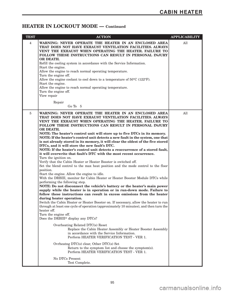
TEST ACTION APPLICABILITY
4WARNING: NEVER OPERATE THE HEATER IN AN ENCLOSED AREA
THAT DOES NOT HAVE EXHAUST VENTILATION FACILITIES. ALWAYS
VENT THE EXHAUST WHEN OPERATING THE HEATER. FAILURE TO
FOLLOW THESE INSTRUCTIONS CAN RESULT IN PERSONAL INJURY
OR DEATH.
Refill the cooling system in accordance with the Service Information.
Start the engine.
Allow the engine to reach normal operating temperature.
Turn the engine off.
Allow the engine coolant to cool down to a temperature of 50ÉC (122ÉF).
Start the engine.
Allow the engine to reach normal operating temperature.
Turn the engine off.
View repairAll
Repair
Go To 5
5WARNING: NEVER OPERATE THE HEATER IN AN ENCLOSED AREA
THAT DOES NOT HAVE EXHAUST VENTILATION FACILITIES. ALWAYS
VENT THE EXHAUST WHEN OPERATING THE HEATER. FAILURE TO
FOLLOW THESE INSTRUCTIONS CAN RESULT IN PERSONAL INJURY
OR DEATH.
NOTE: The heater's control unit will store up to five DTCs in its memory.
NOTE: If the heater's control unit detects a new fault in the system, one that
is not already stored in its memory, it will clear the oldest of the five stored
DTCs, and it will store the new fault's DTC.
NOTE: If the heater's control unit detects a reoccurrence of a stored fault,
it will overwrite that fault's DTC with the most recent occurrence.
Turn the ignition on.
Verify that the Cabin Heater or Heater Booster is switched off.
Set the blend control to the max heat position and the mode control to the floor
position.
Start the engine. Allow the engine to idle.
With the DRBIII, monitor for Cabin Heater or Heater Booster Module DTCs while
performing the following step.
NOTE: Do not disconnect the vehicle's battery or the heater's main power
supply while the heater is in operation or in run-down mode. Failure to
follow these instructions can result in excess emissions from the heater
during heater operation.
Switch the Cabin Heater or Heater Booster on. If necessary, allow the heater to run
through at least one cycle of operation (approximately 10 minutes), and then turn the
heater off.
Turn the engine off.
Does the DRBIIItdisplay any DTCs?All
Overheating Related DTC(s) Reset
Replace the Cabin Heater Assembly or Heater Booster Assembly
in accordance with the Service Information.
Perform HEATER VERIFICATION TEST - VER 1.
Ovrheatng DTC(s) clear, Other DTC(s) Set
Return to the symptom list and choose the symptom(s).
Perform HEATER VERIFICATION TEST - VER 1.
No DTCs Present
Test Complete.
95
CABIN HEATER
HEATER IN LOCKOUT MODE ÐContinued
Page 425 of 2305

3.2.2 ECM OPERATING MODES
As input signals to the ECM change, the ECM
adjusts its response to the output devices. For
example, the ECM must calculate a different fuel
quantity and fuel timing for engine idle condition
than it would for a wide open throttle condition.
There are several different modes of operation that
determine how the ECM responds to the various
input signals.
Ignition Switch On (Engine Off)
When the ignition is turned on the ECM activates
the glow plug relay for a time period that is deter-
mined by engine coolant temperature, intake air
temperature and battery voltage.
Engine Start-Up Mode
The ECM uses the intake air temperature sensor,
engine temperature sensor and the crankshaft po-
sition sensor (engine speed) inputs to determine
fuel injection quantity.
Normal Driving Modes
Engine idle, warm-up, acceleration, deceleration
and wide open throttle modes are controlled based
on all of the sensor inputs to the ECM. The ECM
uses these sensor inputs to adjust fuel quantity and
fuel injector timing. EGR valve control is performed
using feedback from the oxygen sensor. An oxygen
sensor is located in the exhaust manifold to sample
oxygen content exiting the engine cylinders. The
ECM uses the O2 sensor, along with other sensor
inputs, to govern the amount of exhaust gas recir-
culation to reduce HC (HydroCarbons) and CO
(Carbon Monoxide). Engine coolant is routed
through the base of the EGR valve to provide
additional cooling of the exhaust gas, which further
helps the reductions of emissions. The EGR valve
has a self-cleaning function. When the engine is
shut off, the EGR valve rotates twice to reduce
carbon deposits at the valve seat.
Overheat Production Mode
If the engine temperature is above 105ÉC (221ÉF)
and vehicle speed is above 40 km/h (25 MPH) the
ECM will limit fuel quantity for engine protection.
Limp-In Mode
The ECM utilizes different degrees of engine
limp-in. The ECM is able to limit engine rpm,
engine power output (turbo boost reduction), acti-
vate engine cooling fan or all of these functions
based on the type of fault that is detected. Critical
engine performance faults such as accelerator pedal
position sensor fault will result in a fixed idle speed
of approximately 680 rpm regardless of actual pedalposition. Other less critical faults will result in
power reduction throughout the full range of driv-
ing conditions.
Overspeed Detection Mode
If the ECM detects engine RPM that exceeds
5200 RPM, the ECM will set a DTC in memory,
limit engine RPM to no more than 2500 RPM, and
illuminate the MIL until the DTC is cleared.
After-Run Mode
The ECM transfers RAM information to ROM
and performs an Input/Output state check.
3.2.3 MONITORED CIRCUITS
The ECM is able to monitor and identify most
driveability related trouble conditions. Some cir-
cuits are directly monitored through ECM feedback
circuitry. In addition, the ECM monitors the voltage
state of some circuits and compares those states
with expected values. Other systems are monitored
indirectly when the ECM conducts a rationality test
to identify problems.
Although most subsystems of the engine control
module are either directly or indirectly monitored,
there may be occasions when diagnostic trouble
codes are not immediately identified. For a trouble
code to set, a specific set of conditions must occur
and unless these conditions occur, a DTC will not
set.
3.2.4 SKREEM OVERVIEW
The sentry key remote entry module system
(SKREEM) is designed to prevent unauthorized
vehicle operation. The system consists of a sentry
key remote entry module (SKREEM), ignition
key(s) equipped with a transponder chip and the
ECM. When the ignition switch is turned on, the
SKREEM interrogates the ignition key. If the igni-
tion key is Valid or Invalid, the SKREEM sends a
message to the ECM indicating ignition key status.
Upon receiving this message the ECM will termi-
nate engine operation or allow the engine to con-
tinue to operate.
3.2.5 SKREEM ON-BOARD DIAGNOSTICS
The SKREEM has been programmed to transmit
and monitor many different coded messages as well
as CAN Bus messages. This monitoring is called
On-Board Diagnostics. Certain criteria must be met
for a DTC to be entered into SKREEM memory. The
criteria may be a range of; input voltage, CAN Bus
message or coded messages to the SKREEM. If all
the criteria for monitoring a circuit or function are
met and a fault is detected, a DTC will be stored in
the SKREEM memory and the START ERROR indi-
cator will be turned on in the instrument cluster.
2
GENERAL INFORMATION
Page 716 of 2305
LUBRICATION & MAINTENANCE
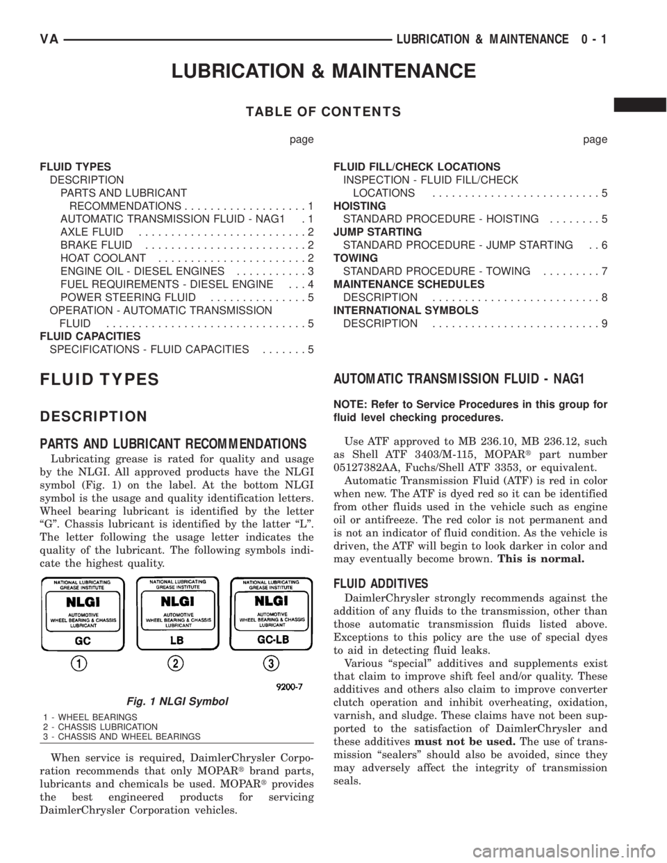
TABLE OF CONTENTS
page page
FLUID TYPES
DESCRIPTION
PARTS AND LUBRICANT
RECOMMENDATIONS...................1
AUTOMATIC TRANSMISSION FLUID - NAG1 . 1
AXLE FLUID..........................2
BRAKE FLUID.........................2
HOAT COOLANT.......................2
ENGINE OIL - DIESEL ENGINES...........3
FUEL REQUIREMENTS - DIESEL ENGINE . . . 4
POWER STEERING FLUID...............5
OPERATION - AUTOMATIC TRANSMISSION
FLUID...............................5
FLUID CAPACITIES
SPECIFICATIONS - FLUID CAPACITIES.......5FLUID FILL/CHECK LOCATIONS
INSPECTION - FLUID FILL/CHECK
LOCATIONS..........................5
HOISTING
STANDARD PROCEDURE - HOISTING........5
JUMP STARTING
STANDARD PROCEDURE - JUMP STARTING . . 6
TOWING
STANDARD PROCEDURE - TOWING.........7
MAINTENANCE SCHEDULES
DESCRIPTION..........................8
INTERNATIONAL SYMBOLS
DESCRIPTION..........................9
FLUID TYPES
DESCRIPTION
PARTS AND LUBRICANT RECOMMENDATIONS
Lubricating grease is rated for quality and usage
by the NLGI. All approved products have the NLGI
symbol (Fig. 1) on the label. At the bottom NLGI
symbol is the usage and quality identification letters.
Wheel bearing lubricant is identified by the letter
ªGº. Chassis lubricant is identified by the latter ªLº.
The letter following the usage letter indicates the
quality of the lubricant. The following symbols indi-
cate the highest quality.
When service is required, DaimlerChrysler Corpo-
ration recommends that only MOPARtbrand parts,
lubricants and chemicals be used. MOPARtprovides
the best engineered products for servicing
DaimlerChrysler Corporation vehicles.
AUTOMATIC TRANSMISSION FLUID - NAG1
NOTE: Refer to Service Procedures in this group for
fluid level checking procedures.
Use ATF approved to MB 236.10, MB 236.12, such
as Shell ATF 3403/M-115, MOPARtpart number
05127382AA, Fuchs/Shell ATF 3353, or equivalent.
Automatic Transmission Fluid (ATF) is red in color
when new. The ATF is dyed red so it can be identified
from other fluids used in the vehicle such as engine
oil or antifreeze. The red color is not permanent and
is not an indicator of fluid condition. As the vehicle is
driven, the ATF will begin to look darker in color and
may eventually become brown.This is normal.
FLUID ADDITIVES
DaimlerChrysler strongly recommends against the
addition of any fluids to the transmission, other than
those automatic transmission fluids listed above.
Exceptions to this policy are the use of special dyes
to aid in detecting fluid leaks.
Various ªspecialº additives and supplements exist
that claim to improve shift feel and/or quality. These
additives and others also claim to improve converter
clutch operation and inhibit overheating, oxidation,
varnish, and sludge. These claims have not been sup-
ported to the satisfaction of DaimlerChrysler and
these additivesmust not be used.The use of trans-
mission ªsealersº should also be avoided, since they
may adversely affect the integrity of transmission
seals.
Fig. 1 NLGI Symbol
1 - WHEEL BEARINGS
2 - CHASSIS LUBRICATION
3 - CHASSIS AND WHEEL BEARINGS
VALUBRICATION & MAINTENANCE 0 - 1
Page 793 of 2305
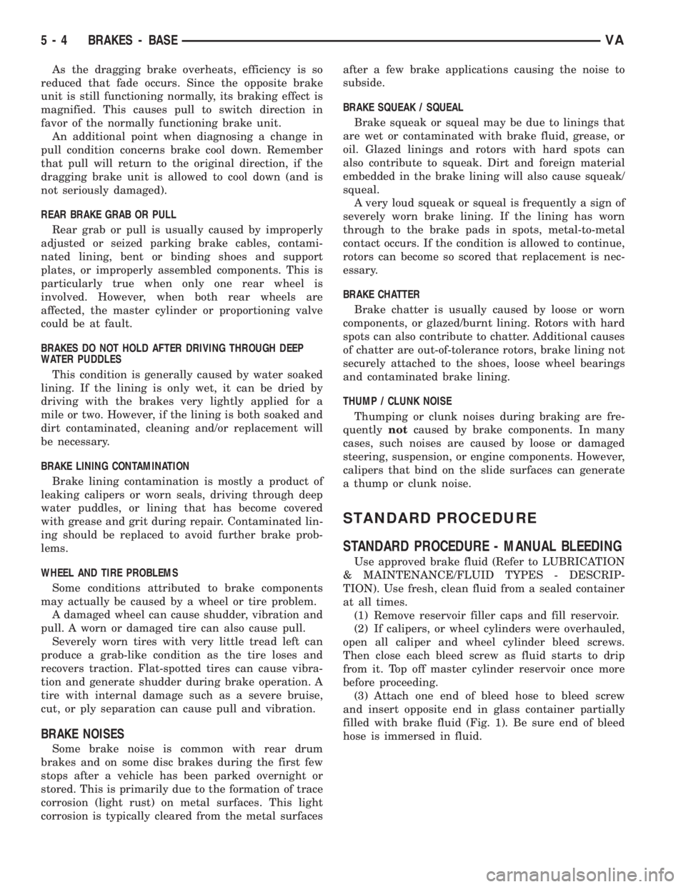
As the dragging brake overheats, efficiency is so
reduced that fade occurs. Since the opposite brake
unit is still functioning normally, its braking effect is
magnified. This causes pull to switch direction in
favor of the normally functioning brake unit.
An additional point when diagnosing a change in
pull condition concerns brake cool down. Remember
that pull will return to the original direction, if the
dragging brake unit is allowed to cool down (and is
not seriously damaged).
REAR BRAKE GRAB OR PULL
Rear grab or pull is usually caused by improperly
adjusted or seized parking brake cables, contami-
nated lining, bent or binding shoes and support
plates, or improperly assembled components. This is
particularly true when only one rear wheel is
involved. However, when both rear wheels are
affected, the master cylinder or proportioning valve
could be at fault.
BRAKES DO NOT HOLD AFTER DRIVING THROUGH DEEP
WATER PUDDLES
This condition is generally caused by water soaked
lining. If the lining is only wet, it can be dried by
driving with the brakes very lightly applied for a
mile or two. However, if the lining is both soaked and
dirt contaminated, cleaning and/or replacement will
be necessary.
BRAKE LINING CONTAMINATION
Brake lining contamination is mostly a product of
leaking calipers or worn seals, driving through deep
water puddles, or lining that has become covered
with grease and grit during repair. Contaminated lin-
ing should be replaced to avoid further brake prob-
lems.
WHEEL AND TIRE PROBLEMS
Some conditions attributed to brake components
may actually be caused by a wheel or tire problem.
A damaged wheel can cause shudder, vibration and
pull. A worn or damaged tire can also cause pull.
Severely worn tires with very little tread left can
produce a grab-like condition as the tire loses and
recovers traction. Flat-spotted tires can cause vibra-
tion and generate shudder during brake operation. A
tire with internal damage such as a severe bruise,
cut, or ply separation can cause pull and vibration.
BRAKE NOISES
Some brake noise is common with rear drum
brakes and on some disc brakes during the first few
stops after a vehicle has been parked overnight or
stored. This is primarily due to the formation of trace
corrosion (light rust) on metal surfaces. This light
corrosion is typically cleared from the metal surfacesafter a few brake applications causing the noise to
subside.
BRAKE SQUEAK / SQUEAL
Brake squeak or squeal may be due to linings that
are wet or contaminated with brake fluid, grease, or
oil. Glazed linings and rotors with hard spots can
also contribute to squeak. Dirt and foreign material
embedded in the brake lining will also cause squeak/
squeal.
A very loud squeak or squeal is frequently a sign of
severely worn brake lining. If the lining has worn
through to the brake pads in spots, metal-to-metal
contact occurs. If the condition is allowed to continue,
rotors can become so scored that replacement is nec-
essary.
BRAKE CHATTER
Brake chatter is usually caused by loose or worn
components, or glazed/burnt lining. Rotors with hard
spots can also contribute to chatter. Additional causes
of chatter are out-of-tolerance rotors, brake lining not
securely attached to the shoes, loose wheel bearings
and contaminated brake lining.
THUMP / CLUNK NOISE
Thumping or clunk noises during braking are fre-
quentlynotcaused by brake components. In many
cases, such noises are caused by loose or damaged
steering, suspension, or engine components. However,
calipers that bind on the slide surfaces can generate
a thump or clunk noise.
STANDARD PROCEDURE
STANDARD PROCEDURE - MANUAL BLEEDING
Use approved brake fluid (Refer to LUBRICATION
& MAINTENANCE/FLUID TYPES - DESCRIP-
TION). Use fresh, clean fluid from a sealed container
at all times.
(1) Remove reservoir filler caps and fill reservoir.
(2) If calipers, or wheel cylinders were overhauled,
open all caliper and wheel cylinder bleed screws.
Then close each bleed screw as fluid starts to drip
from it. Top off master cylinder reservoir once more
before proceeding.
(3) Attach one end of bleed hose to bleed screw
and insert opposite end in glass container partially
filled with brake fluid (Fig. 1). Be sure end of bleed
hose is immersed in fluid.
5 - 4 BRAKES - BASEVA
Page 828 of 2305
COOLING
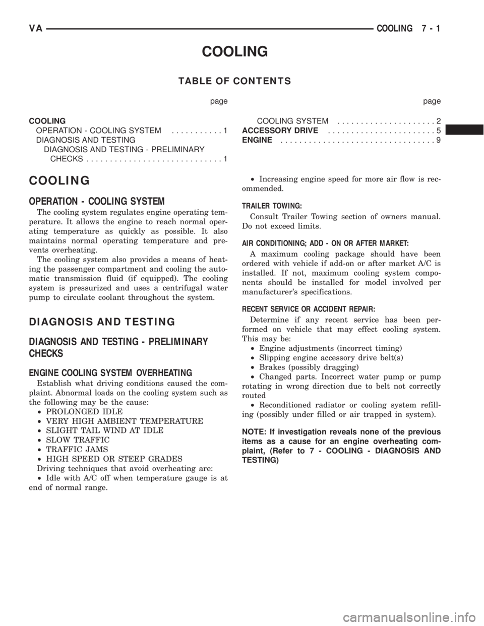
TABLE OF CONTENTS
page page
COOLING
OPERATION - COOLING SYSTEM...........1
DIAGNOSIS AND TESTING
DIAGNOSIS AND TESTING - PRELIMINARY
CHECKS.............................1COOLING SYSTEM.....................2
ACCESSORY DRIVE.......................5
ENGINE.................................9
COOLING
OPERATION - COOLING SYSTEM
The cooling system regulates engine operating tem-
perature. It allows the engine to reach normal oper-
ating temperature as quickly as possible. It also
maintains normal operating temperature and pre-
vents overheating.
The cooling system also provides a means of heat-
ing the passenger compartment and cooling the auto-
matic transmission fluid (if equipped). The cooling
system is pressurized and uses a centrifugal water
pump to circulate coolant throughout the system.
DIAGNOSIS AND TESTING
DIAGNOSIS AND TESTING - PRELIMINARY
CHECKS
ENGINE COOLING SYSTEM OVERHEATING
Establish what driving conditions caused the com-
plaint. Abnormal loads on the cooling system such as
the following may be the cause:
²PROLONGED IDLE
²VERY HIGH AMBIENT TEMPERATURE
²SLIGHT TAIL WIND AT IDLE
²SLOW TRAFFIC
²TRAFFIC JAMS
²HIGH SPEED OR STEEP GRADES
Driving techniques that avoid overheating are:
²Idle with A/C off when temperature gauge is at
end of normal range.²Increasing engine speed for more air flow is rec-
ommended.
TRAILER TOWING:
Consult Trailer Towing section of owners manual.
Do not exceed limits.
AIR CONDITIONING; ADD - ON OR AFTER MARKET:
A maximum cooling package should have been
ordered with vehicle if add-on or after market A/C is
installed. If not, maximum cooling system compo-
nents should be installed for model involved per
manufacturer's specifications.
RECENT SERVICE OR ACCIDENT REPAIR:
Determine if any recent service has been per-
formed on vehicle that may effect cooling system.
This may be:
²Engine adjustments (incorrect timing)
²Slipping engine accessory drive belt(s)
²Brakes (possibly dragging)
²Changed parts. Incorrect water pump or pump
rotating in wrong direction due to belt not correctly
routed
²Reconditioned radiator or cooling system refill-
ing (possibly under filled or air trapped in system).
NOTE: If investigation reveals none of the previous
items as a cause for an engine overheating com-
plaint, (Refer to 7 - COOLING - DIAGNOSIS AND
TESTING)
VACOOLING 7 - 1
Page 835 of 2305
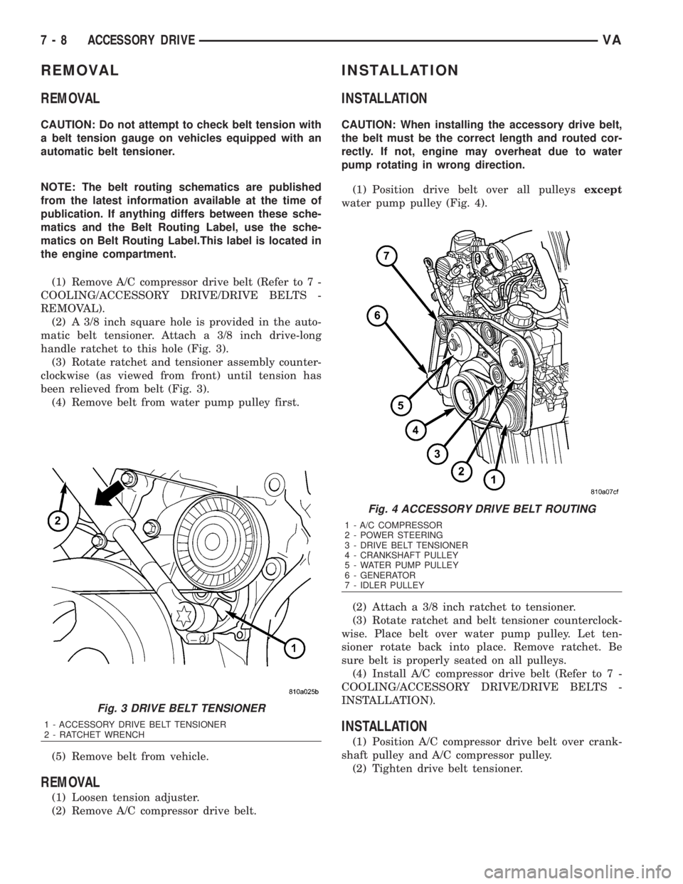
REMOVAL
REMOVAL
CAUTION: Do not attempt to check belt tension with
a belt tension gauge on vehicles equipped with an
automatic belt tensioner.
NOTE: The belt routing schematics are published
from the latest information available at the time of
publication. If anything differs between these sche-
matics and the Belt Routing Label, use the sche-
matics on Belt Routing Label.This label is located in
the engine compartment.
(1) Remove A/C compressor drive belt (Refer to 7 -
COOLING/ACCESSORY DRIVE/DRIVE BELTS -
REMOVAL).
(2) A 3/8 inch square hole is provided in the auto-
matic belt tensioner. Attach a 3/8 inch drive-long
handle ratchet to this hole (Fig. 3).
(3) Rotate ratchet and tensioner assembly counter-
clockwise (as viewed from front) until tension has
been relieved from belt (Fig. 3).
(4) Remove belt from water pump pulley first.
(5) Remove belt from vehicle.
REMOVAL
(1) Loosen tension adjuster.
(2) Remove A/C compressor drive belt.
INSTALLATION
INSTALLATION
CAUTION: When installing the accessory drive belt,
the belt must be the correct length and routed cor-
rectly. If not, engine may overheat due to water
pump rotating in wrong direction.
(1) Position drive belt over all pulleysexcept
water pump pulley (Fig. 4).
(2) Attach a 3/8 inch ratchet to tensioner.
(3) Rotate ratchet and belt tensioner counterclock-
wise. Place belt over water pump pulley. Let ten-
sioner rotate back into place. Remove ratchet. Be
sure belt is properly seated on all pulleys.
(4) Install A/C compressor drive belt (Refer to 7 -
COOLING/ACCESSORY DRIVE/DRIVE BELTS -
INSTALLATION).
INSTALLATION
(1) Position A/C compressor drive belt over crank-
shaft pulley and A/C compressor pulley.
(2) Tighten drive belt tensioner.
Fig. 3 DRIVE BELT TENSIONER
1 - ACCESSORY DRIVE BELT TENSIONER
2 - RATCHET WRENCH
Fig. 4 ACCESSORY DRIVE BELT ROUTING
1 - A/C COMPRESSOR
2 - POWER STEERING
3 - DRIVE BELT TENSIONER
4 - CRANKSHAFT PULLEY
5 - WATER PUMP PULLEY
6 - GENERATOR
7 - IDLER PULLEY
7 - 8 ACCESSORY DRIVEVA