2006 MERCEDES-BENZ SPRINTER fuel cap
[x] Cancel search: fuel capPage 21 of 2305

reaching operating temperature. The heater's con-
trol unit controls and monitors combustion opera-
tion through various inputs and outputs that are
contained inside the heater assembly. The supple-
mental heater connects to the vehicle's heater hoses
and uses a separate fuel supply line and fuel pump
that connects to the vehicle's fuel tank. Unlike the
Heater Booster, the Cabin Heater Assembly has an
integral coolant pump which allows heater opera-
tion without the vehicle's engine running. In addi-
tion, a programmable timer module can also be
added to this system. Neither the Cabin Heater
Assembly nor the Heater Booster Assembly are
connected to the CAN Bus. Communication be-
tween the heater's control unit and the DRBIIIt
occurs through the Diagnostic Link Connector
(DLC) via a K-Line.
3.3.2.2 VENTING THE HEATER'S EXHAUST
WARNING: NEVER OPERATE THE HEATER
IN AN ENCLOSED AREA THAT DOES NOT
HAVE EXHAUST VENTILATION FACILITIES.
ALWAYS VENT THE HEATER'S EXHAUST
WHEN OPERATING THE HEATER. FAILURE
TO FOLLOW THESE INSTRUCTIONS CAN
RESULT IN PERSONAL INJURY OR DEATH.
WARNING:
ALLOW THE HEATER ASSEMBLY TO
COOL BEFORE PERFORMING A COMPONENT
INSPECTION/REPAIR/REPLACEMENT. FAILURE
TO FOLLOW THESE INSTRUCTIONS CAN
RESULT IN PERSONAL INJURY OR DEATH.
CAUTION: When using a powered exhaust
ventilation system, do not attach the exhaust
ventilation hose directly to the heater's
exhaust pipe. Too much suction can prevent
heater operation.
When using a powered exhaust ventilation sys-
tem, affix the ventilation hose to the heater's ex-
haust pipe or to the vehicle in such a manor that the
end of the ventilation hose remains approximately
three inches away from the end of the heater's
exhaust pipe.
When using a non-powered exhaust ventilation
system, affix the ventilation hose directly to the
heater's exhaust pipe.
3.3.2.3 SYSTEM DIAGNOSTICS
CAUTION: Always Perform The Heater
Pre-Test (In The Diagnostic Procedures) Prior
To Performing Any Other Test For The Test
Result To Be Valid.
Fault detection is through stored Diagnostic
Trouble Codes (DTCs). DTCs are displayed by the
DRBIIIt. The heater's control unit will store up to
five DTCs in its memory. If the control unit detects
a new fault in the system, one that is not already
stored in its memory, it will clear the oldest of the
five stored DTCs, and it will store the new fault's
DTC. If the control unit detects a reoccurrence of a
stored fault, it will overwrite that fault's DTC with
the most recent occurrence.
DIAGNOSTIC TIPS
SENSOR VALUES
Operating Voltage
The normal range for the Operating Voltage is from
10 volts to 15 volts. The value indicates the voltage
at the heater 's Fused B+ terminal.
Heating Capacity
The normal range for the heating capacity is from
0% to 100%. The value indicates the momentary
output of the auxiliary heater in % of the maximum
output.
Coolant Temperature
The value indicates the current coolant tempera-
ture.
Flame Sensor Resistance
The normal range for the Flame Sensor is from 750
ohms to 2270 ohms. The value indicates the mo-
mentary resistance of the Flame Sensor.
INPUT/OUTPUT STATUS
Dosing Pump
A status of9ON9indicates that the Dosing Pump is
operational. A status of9OFF9indicates the Dosing
Pump is not operational.
Glow Pin
A status of9ON9indicates that the Glow Pin is
energized. A status of9OFF9indicates the Glow Pin
is not energized.
Combustion Fan
A status of9ON9indicates that the Combustion Fan
is operational. A status of9OFF9indicates the
Combustion Fan is not operational.
Circulation Pump
A status of9ON9indicates that the Circulation
Pump is operational. A status of9OFF9indicates the
Circulation Pump is not operational.
Front End Blower
A status of9ON9indicates that the Blower Motor is
operational. A status of9OFF9indicates the Blower
Motor is not operational.
8
GENERAL INFORMATION
Page 22 of 2305
Static Heater Signal
A status of9ON9indicates that the heater module
sees the9Stationary Heating Mode ON9signal after
switching on the heater with the heater timer or the
auxiliary heater switch. A status of9OFF9indicates
that the9Stationary Heating Mode ON9signal is
not present at the heater module.
Heater Booster Mode Signal
A status of9ON9indicates that the heater module
sees the9Heater Booster Mode ON9signal after
switching on the heater with the auxiliary heater
switch. A status of9OFF9indicates that the9Heater
Booster Mode ON9signal is not present at the
heater module.
3.4 INSTRUMENT CLUSTER
The Instrument Cluster has easy-to-read instru-
ments, is capable of CAN bus communication and
provides a diagnostic function. The Instrument
Cluster with analog speedometer, tachometer, fuel
and coolant temperature gauges comes in two ver-
sions.
²Speedometer with outer miles-per-hour (mph)
scale and inner kilometers-per-hour (km/h) scale.
Coolant temperature is indicated in Fahrenheit
(for US).
²Speedometer with outer kilometers-per-hour
(km/h) scale and inner miles-per-hours (mph)
scale. Coolant temperature is indicated in de-
grees Celsius (for Canada).
Below the speedometer, there is a LCD multi-
function indicator in clear view of the driver. Warn-
ing and indicator lights (based on colored light
emitting diodes) are located in the bottom of the
instrument cluster with the exception of the turn
signal indicator lights, ASR warning light and re-
serve fuel warning light. The warning lights for the
seat belt usage and parking brake/brake fluid level
are located in the line above the bottom line. The
indicator that illuminates up when the parking
brake is applied or the brake fluid level is low is
different for U.S. and Canada.
When the key is turned to the 2nd position in the
ignition, the function of the following indicator
lights is checked automatically: High Beam ON,
Preheating, airbag malfunction. In case of a broken
LED of the airbag malfunction light, the seat belt
usage warning light will flash for 6 seconds after
the function check is finished. The Instrument
Cluster is operated with the help of 4 buttons
located below the multifunction indicator. The back-
lighting for the instrument cluster uses yellow
LED's and can be adjusted electronically to daylight
and darkness.The instrument cluster includes a warning
buzzer, which sounds (in addition to a warning light
in some cases) when:
²The headlights are on with the ignition off and
the door opened.
²The driver 's seat belt is not fastened with the
ignition on.
²The key is in the ignition and the door is open.
²Critical ASSYST information is displayed in the
multifunction indicator.
3.5 POWER DOOR LOCKS/RKE
3.5.1 CENTRAL LOCKING
The Central Locking System locks all vehicle
doors if any door is locked from the inside or
mechanically locked with the key from the outside.
However, unlocking any door, in that manner, will
only unlock that particular door. The Master Door
Lock Switch on the dash enables the operator to
lock/unlock all doors. By pressing the top of the
rocker type switch once, all doors will lock. Pressing
the switch again will unlock all doors. Pressing the
lower part of the switch once will lock all doors
except the driver door. Pressing the lower part
again will unlock all doors except the driver door. If
the Central Locking System automatically unlocks
after the vehicle was attempted to be locked, at
least one door is not properly closed.
There are two LED indicators in the Master Door
Lock Switch. The left indicator is for the driver door
and the right indicator is for all passenger/cargo
doors. These will indicate if a door is ajar or if the
doors are locked. The door ajar switches are part of
the door lock motor and are mounted in the door
latch assembly.
Inside each door lock motor there is a command
switch. The command switch is operated by the
plunger and signals any change in the lock status,
locked or unlocked. Each command switch is wired
to the Central Timer Module (CTM) sometimes
referred to as the Central Locking Module. If all
doors are closed and are unlocked, and any door is
locked by the key or the interior handle, thereby
changing the command switch, all doors will be
locked. If one of the door lock motors does not reach
the end position after a locking command, it will be
detected by the CTM (command switch not in
9Locked9position) and the vehicle will be unlocked.
3.5.2 REMOTE KEYLESS ENTRY (RKE)
The SKREEM is a combination of the Remote
Keyless Entry Module and the SKIM (Sentry Key
Immobilizer Module). It is located behind the In-
strument Cluster and has an antenna that goes up
9
GENERAL INFORMATION
Page 716 of 2305
LUBRICATION & MAINTENANCE
TABLE OF CONTENTS
page page
FLUID TYPES
DESCRIPTION
PARTS AND LUBRICANT
RECOMMENDATIONS...................1
AUTOMATIC TRANSMISSION FLUID - NAG1 . 1
AXLE FLUID..........................2
BRAKE FLUID.........................2
HOAT COOLANT.......................2
ENGINE OIL - DIESEL ENGINES...........3
FUEL REQUIREMENTS - DIESEL ENGINE . . . 4
POWER STEERING FLUID...............5
OPERATION - AUTOMATIC TRANSMISSION
FLUID...............................5
FLUID CAPACITIES
SPECIFICATIONS - FLUID CAPACITIES.......5FLUID FILL/CHECK LOCATIONS
INSPECTION - FLUID FILL/CHECK
LOCATIONS..........................5
HOISTING
STANDARD PROCEDURE - HOISTING........5
JUMP STARTING
STANDARD PROCEDURE - JUMP STARTING . . 6
TOWING
STANDARD PROCEDURE - TOWING.........7
MAINTENANCE SCHEDULES
DESCRIPTION..........................8
INTERNATIONAL SYMBOLS
DESCRIPTION..........................9
FLUID TYPES
DESCRIPTION
PARTS AND LUBRICANT RECOMMENDATIONS
Lubricating grease is rated for quality and usage
by the NLGI. All approved products have the NLGI
symbol (Fig. 1) on the label. At the bottom NLGI
symbol is the usage and quality identification letters.
Wheel bearing lubricant is identified by the letter
ªGº. Chassis lubricant is identified by the latter ªLº.
The letter following the usage letter indicates the
quality of the lubricant. The following symbols indi-
cate the highest quality.
When service is required, DaimlerChrysler Corpo-
ration recommends that only MOPARtbrand parts,
lubricants and chemicals be used. MOPARtprovides
the best engineered products for servicing
DaimlerChrysler Corporation vehicles.
AUTOMATIC TRANSMISSION FLUID - NAG1
NOTE: Refer to Service Procedures in this group for
fluid level checking procedures.
Use ATF approved to MB 236.10, MB 236.12, such
as Shell ATF 3403/M-115, MOPARtpart number
05127382AA, Fuchs/Shell ATF 3353, or equivalent.
Automatic Transmission Fluid (ATF) is red in color
when new. The ATF is dyed red so it can be identified
from other fluids used in the vehicle such as engine
oil or antifreeze. The red color is not permanent and
is not an indicator of fluid condition. As the vehicle is
driven, the ATF will begin to look darker in color and
may eventually become brown.This is normal.
FLUID ADDITIVES
DaimlerChrysler strongly recommends against the
addition of any fluids to the transmission, other than
those automatic transmission fluids listed above.
Exceptions to this policy are the use of special dyes
to aid in detecting fluid leaks.
Various ªspecialº additives and supplements exist
that claim to improve shift feel and/or quality. These
additives and others also claim to improve converter
clutch operation and inhibit overheating, oxidation,
varnish, and sludge. These claims have not been sup-
ported to the satisfaction of DaimlerChrysler and
these additivesmust not be used.The use of trans-
mission ªsealersº should also be avoided, since they
may adversely affect the integrity of transmission
seals.
Fig. 1 NLGI Symbol
1 - WHEEL BEARINGS
2 - CHASSIS LUBRICATION
3 - CHASSIS AND WHEEL BEARINGS
VALUBRICATION & MAINTENANCE 0 - 1
Page 720 of 2305
Do not blend other specific fuel additives with die-
sel fuel. They only result in unnecessary cost, and
may be harmful to the engine operation.
POWER STEERING FLUID
No fluid service required. Filled with Power Steer-
ing Fluid approved to MB 236.3, such as Mobil
ATF-D (Exxon Mobil Corporation) or equivalent.
OPERATION - AUTOMATIC TRANSMISSION
FLUID
The automatic transmission fluid is selected based
upon several qualities. The fluid must provide a high
level of protection for the internal components by
providing a lubricating film between adjacent metal
components. The fluid must also be thermally stable
so that it can maintain a consistent viscosity through
a large temperature range. If the viscosity stays con-
stant through the temperature range of operation,
transmission operation and shift feel will remain con-
sistent. Transmission fluid must also be a good con-
ductor of heat. The fluid must absorb heat from the
internal transmission components and transfer that
heat to the transmission case.
FLUID CAPACITIES
SPECIFICATIONS - FLUID CAPACITIES
DESCRIPTION SPECIFICATION
ENGINE COOLANT
10 Liters 10.5 Quarts
ENGINE OIL
9.0L without Filter Re-
placement9.5 Quarts with Filter
Replacement
AUTOMATIC TRANSMISSION
Service Fill - NAG1 5.0 L (10.6 pts.)
O-haul Fill - NAG1 7.7 L (16.3 pts.)
Dry fill capacity Depending on type and size of inter-
nal cooler, length and inside diameter of cooler lines,
or use of an auxiliary cooler, these figures may vary.
(Refer to appropriate 21 - TRANSMISSION/AUTO-
MATIC/FLUID - STANDARD PROCEDURE).
REAR AXLE .03L (1 oz.)
8 1/2 1.8 L (4.0 pts.)
FUEL TANK
Primary 100 L (26.4 gal.)*
Reserve 10.5 L (2.8 gal.)*
*Nominal refill capacities are shown. A variation may
be observed from vehicle to vehicle due to manufac-
turing tolerance and refill procedure
DESCRIPTION SPECIFICATION
POWER STEERING SYSTEM
Power steering fluid capacities are dependent on
engine/chassis options as well as steering gear/cool-
er options. Depending on type and size of internal
cooler, length and inside diameter of cooler lines, or
use of an auxiliary cooler, these capacities may vary.
Refer to 19, Steering for proper fill and bleed proce-
dures.
FLUID FILL / CHECK LOCA-
TIONS
INSPECTION - FLUID FILL / CHECK LOCA-
TIONS
The fluid fill/check locations and lubrication points
are located in each applicable group.
HOISTING
STANDARD PROCEDURE - HOISTING
Refer to the Owner's Manual for emergency vehicle
lifting procedures.
WARNING: THE HOISTING AND JACK LIFTING
POINTS PROVIDED ARE FOR A COMPLETE VEHI-
CLE. WHEN A CHASSIS OR DRIVETRAIN COMPO-
NENT IS REMOVED FROM A VEHICLE, THE
CENTER OF GRAVITY IS ALTERED MAKING SOME
HOISTING CONDITIONS UNSTABLE. PROPERLY
SUPPORT OR SECURE VEHICLE TO HOISTING
DEVICE WHEN THESE CONDITIONS EXIST.
FLOOR JACK
When properly positioned, a floor jack can be used
to lift a vehicle. Support the vehicle in the raised
position with jack stands at the front and rear ends
of the frame rails.
CAUTION: Do not lift vehicle with a floor jack posi-
tioned under:
²An axle tube.
²A body side sill.
²A steering linkage component.
²A drive shaft.
²The engine or transmission oil pan.
²The fuel tank.
²A front suspension arm.
VALUBRICATION & MAINTENANCE 0 - 5
Page 843 of 2305

(3) Refill coolant system to proper level with
proper mixture of coolant (Refer to 7 - COOLING/
ENGINE/COOLANT - STANDARD PROCEDURE).
(4) Install engine cover (Refer to 9 - ENGINE -
INSTALLATION).
(5) Connect negative battery cable.
WARNING: Use extreme caution when engine is
operating. Do not stand in a direct line with fan. do
not put your hands near pulleys, belts or fan. Do
not wear loose clothes.
(6) Start engine and inspect for leaks.
ENGINE COOLANT THERMO-
STAT
REMOVAL
WARNING: RISK OF INJURY TO SKIN AND EYES
FROM SCALDING WITH HOT COOLANT. RISK OF
POISONING FROM SWALLOWING COOLANT. DO
NOT OPEN COOLING SYSTEM UNLESS COOLANT
TEMPERATURE IS BELOW 90ÉC (194ÉF). OPEN CAP
SLOWLY TO RELEASE PRESSURE. STORE COOL-
ANT IN SUITABLE AND APPROPRIATELY MARKED
CONTAINER. WEAR PROTECTIVE GLOVES,
CLOTHES AND EYE WEAR.
NOTE: Inspect condition of all clamps and hoses,
replace as necessary.
(1) Disconnect negative battery cable.
(2) Partially drain engine coolant (Refer to 7 -
COOLING/ENGINE/COOLANT - STANDARD PRO-
CEDURE).
(3) Unplug connector, pull off locking element and
pull out coolant temperature sensor.
(4) Detach air intake hose at charge air distribu-
tion pipe.
(5) Detach coolant hoses at thermostat housing.
(6) Unscrew cap at oil filter housing.
(7) Remove thermostat housing (Fig. 8).(8) Clean all sealing surfaces.
INSTALLATION
(1) Clean all sealing surfaces.
(2) Position and install thermostat housing with
new gasket (Fig. 8). Tighten bolts to 9N´m (80
lbs.in.).
NOTE: Inspect condition of all clamps and hoses,
replace as necessary.
(3) Install cap at oil filter housing.
(4) Connect coolant hoses and vent hose (Fig. 8).
(5) Attach air intake hose at charge air distribu-
tion pipe.
(6) Close coolant drain.
(7) Connect negative battery cable.
(8) Fill coolant system to proper level with appro-
priate coolant mixture (Refer to 7 - COOLING/EN-
GINE/COOLANT - STANDARD PROCEDURE).
WARNING: USE EXTREME CAUTION WHEN ENGINE
IS OPERATING. DO NOT STAND IN DIRECT LINE
WITH FAN. DO NOT PUT YOUR HANDS NEAR PUL-
LEYS, BELTS OR FAN. DO NOT WEAR LOOSE
CLOTHES.
(9) Start engine and inspect for leaks.
Fig. 8 THERMOSTAT HOUSING ASSEMBLY
1 - O-RING
2 - CLAMP
3 - COOLANT TEMPERATURE SENSOR
4 - FUEL LINE W/BRACKET
5 - THERMOSTAT HOUSING ASSEMBLY
6 - COOLANT HOSE
7 - CLAMP
8 - COOLANT HOSE
9 - GASKET
7 - 16 ENGINEVA
Page 849 of 2305
(6) Press off cap at belt guide pulleys.
(7) Remove belt guide pulleys.
(8) Remove water pump retaining bolts and
remove water pump.
INSTALLATION
NOTE: Clean all mating surfaces.
(1) Fit existing accessory drive belt pulley onto the
water pump.
(2) Properly position water pump with new gasket
to the engine and tighten bolts to 14 N´m (124 lbs.
in)., M8 (20 N´m (177 lbs. in.) (Fig. 13).
NOTE: Be sure to install the washer behind the
guide pulley to assure proper alignment.
(3) Install belt guide pulleys. Tighten bolts to 35
N´m (26 lbs. ft.) (Fig. 13).
(4) Attach the coolant hoses to the water pump
and tighten clamps (Fig. 13).
(5) Attach fuel lines to the brackets at the water
pump.(6) Install accessory drive belt.
(7) Install viscous fan clutch.
(8) Close radiator and or engine drain plug.
(9) Refill cooling system to proper level (Refer to 7
- COOLING/ENGINE/COOLANT - STANDARD PRO-
CEDURE). Check for leaks.
Fig. 13 WATER PUMP
1 - GASKET 5 - CAP
2 - WASHER 6 - WATER PUMP
3 - GUIDE PULLEY 7 - COOLANT HOSE
4 - BOLT 8 - COOLANT HOSE
7 - 22 ENGINEVA
Page 895 of 2305
Starting System Diagnosis
CONDITION POSSIBLE CAUSE CORRECTION
STARTER DOES NOT
DISENGAGE.1. Starter motor improp-
erly installed.1. Refer to Starter Motor Removal and Installation.
Tighten starter mounting hardware to correct torque
specifications.
2. Starter relay faulty. 2. Refer to Starter Relay Diagnosis and Testing. Re-
place starter relay if required.
3. Ignition switch faulty. 3. Refer to Ignition Switch and Key Lock Cylinder. Re-
place ignition switch if required.
4. Starter motor faulty. 4. If all other starting system components and circuits
test OK, replace starter motor.
INSPECTION
For complete starter wiring circuit diagrams, refer
to 8, Wiring Diagrams. Before removing any unit
from starting system for repair or diagnosis, perform
the following inspections:
WARNING: ON VEHICLES EQUIPPED WITH AIR-
BAGS, REFER TO 8, PASSIVE RESTRAINT SYS-
TEMS, BEFORE ATTEMPTING ANY STEERING
WHEEL, STEERING COLUMN, OR INSTRUMENT
PANEL COMPONENT DIAGNOSIS OR SERVICE.
FAILURE TO TAKE THE PROPER PRECAUTIONS
COULD RESULT IN ACCIDENTAL AIRBAG DEPLOY-
MENT AND POSSIBLE PERSONAL INJURY.
²Battery- Visually inspect battery for indica-
tions of physical damage and loose or corroded cable
connections. Determine state-of-charge and cranking
capacity of battery. Charge or replace battery if
required. Refer toBatteryin 8, Battery.
²Ignition Switch- Visually inspect ignition
switch for indications of physical damage and loose
or corroded wire harness connections. Refer toIgni-
tion Switch and Key Lock Cylinder.
²Park/Neutral Position Switch- Visually
inspect park/neutral position switch for indications of
physical damage and loose or corroded wire harness
connections. Refer toPark/Neutral Position
Switchin 21, Transmission.
²Starter Relay- Visually inspect starter relay
for indications of physical damage and loose or cor-
roded wire harness connections.
²Starter Motor- Visually inspect starter motor
for indications of physical damage and loose or cor-
roded wire harness connections.
²Starter Solenoid- Visually inspect starter sole-
noid for indications of physical damage and loose or
corroded wire harness connections.
²Wiring- Visually inspect wire harnesses for
damage or corrosion. Repair or replace any faulty
wiring, as required. Refer to 8, Wiring Diagrams.
TESTING
COLD CRANKING TEST
For complete starter wiring circuit diagrams, refer
to 8, Wiring Diagrams. The battery must be fully-
charged and load-tested before proceeding. Refer to
Batteryin 8, Battery.
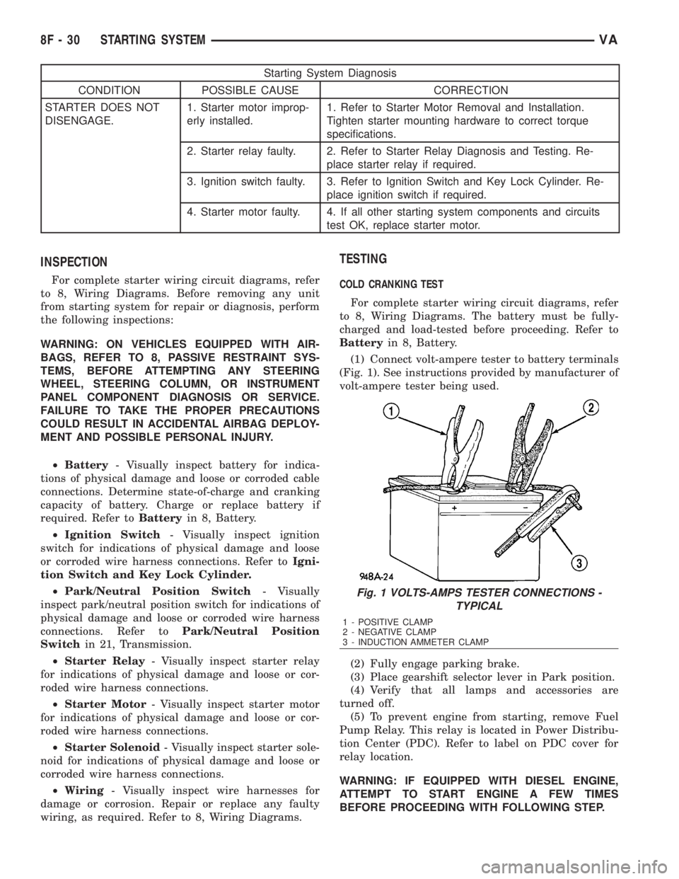
(1) Connect volt-ampere tester to battery terminals
(Fig. 1). See instructions provided by manufacturer of
volt-ampere tester being used.
(2) Fully engage parking brake.
(3) Place gearshift selector lever in Park position.
(4) Verify that all lamps and accessories are
turned off.
(5) To prevent engine from starting, remove Fuel
Pump Relay. This relay is located in Power Distribu-
tion Center (PDC). Refer to label on PDC cover for
relay location.
WARNING: IF EQUIPPED WITH DIESEL ENGINE,
ATTEMPT TO START ENGINE A FEW TIMES
BEFORE PROCEEDING WITH FOLLOWING STEP.
Fig. 1 VOLTS-AMPS TESTER CONNECTIONS -
TYPICAL
1 - POSITIVE CLAMP
2 - NEGATIVE CLAMP
3 - INDUCTION AMMETER CLAMP
8F - 30 STARTING SYSTEMVA
Page 926 of 2305

GROUNDS
The EMIC receives and supplies a ground path to
several switches and sensors through the following
hard wired circuits:
²Ambient Temperature Sensor Return
(Optional)
²Fuel Level Sensor Return
²Ground
Refer to the appropriate wiring information for
additional details.
COMMUNICATION
The EMIC has provisions for the following commu-
nication circuits:
²CAN Data Bus - High
²CAN Data Bus - Low
²Diagnostic Serial Communication Interface
(SCI) Data Bus Line
Refer to the appropriate wiring information for
additional details.
DIAGNOSIS AND TESTING - INSTRUMENT
CLUSTER
The hard wired inputs to and outputs from the
instrument cluster may be diagnosed and tested
using conventional diagnostic tools and procedures.
Refer to the appropriate wiring information. The wir-
ing information includes wiring diagrams, proper
wire and connector repair procedures, details of wire
harness routing and retention, connector pin-out
information and location views for the various wire
harness connectors, splices and grounds.
If the instrument cluster is completely inoperative,
be certain to check the fused B(+) circuit fuses and
wiring for the instrument cluster. If the cluster gen-
eral illumination is inoperative, be certain to check
the instrument lighting fuse and the input circuit to
the instrument cluster from the exterior lighting cir-
cuitry of the multi-function switch on the steering
column.
Conventional diagnostic methods may not prove
conclusive in the diagnosis of the instrument cluster.
In order to obtain conclusive testing of the instru-
ment cluster, the Controller Area Network (CAN)
data bus network and all of the electronic modules
that provide inputs to or receive outputs from the
instrument cluster must also be checked. The most
reliable, efficient, and accurate means to diagnose
the instrument cluster, the CAN data bus network,
and the electronic modules that provide inputs to or
receive outputs from the instrument cluster requires
the use of a diagnostic scan tool and the appropriate
diagnostic information. The diagnostic scan tool can
provide confirmation that the CAN data bus network
is functional, that all of the modules are sending and
receiving the proper electronic messages over the
CAN data bus, and that the instrument cluster isreceiving the proper hard wired inputs and respond-
ing with the proper hard wired outputs needed to
perform its many functions.
WARNING: To avoid personal injury or death, on
vehicles equipped with airbags, disable the supple-
mental restraint system before attempting any
steering wheel, steering column, airbag, seat belt
tensioner, or instrument panel component diagno-
sis or service. Disconnect and isolate the battery
negative (ground) cable, then wait two minutes for
the system capacitor to discharge before perform-
ing further diagnosis or service. This is the only
sure way to disable the supplemental restraint sys-
tem. Failure to take the proper precautions could
result in accidental airbag deployment.
STANDARD PROCEDURE
CLUSTER PROGRAMMING
NOTE: After replacing the Instrument Cluster (IC)
according to the service procedures, determine the
optional equipment on the vehicle by accessing the
sales code information using the Vehicle Identifica-
tion Number (VIN) on DealerCONNECT.
(1) Using the DRBIIIt, selectMISCELLANEOUS
FUNCTIONSin the Instrument Cluster (IC) section.
(2) SelectMODULE SERVICE REPLACE-
MENT.
(3) Following the prompts on the DRBIIIt, enter
the correct parameters that are applicable to the
vehicle. Use the sales code information and visual
inspection to obtain the correct parameters.
CAUTION: Do not lock down the instrument cluster
until the following steps are followed or the instru-
ment cluster may be irreversibly damaged.
(4) After entering the proper parameters into the
IC, turn the ignition switch to the OFF position for
30 seconds, then turn the ignition switch ON.
(5) Test drive the vehicle for at least 10 minutes
before proceeding.
(6) Check ALL modules for any parameterization
DTCs. If any parameterization DTCs are present, one
or more parameters entered into the IC are incorrect.
Verify all parameters entered using the sales code
information and visual inspection of the vehicle.
(7) If the parameters entered are verified as cor-
rect and parameterization DTCs are still present,
refer to the appropriate diagnostic information.
(8) If no parameterization DTCs are present, lock
down the IC.
VAINSTRUMENT CLUSTER 8J - 7