2006 MERCEDES-BENZ SPRINTER coolant capacity
[x] Cancel search: coolant capacityPage 21 of 2305

reaching operating temperature. The heater's con-
trol unit controls and monitors combustion opera-
tion through various inputs and outputs that are
contained inside the heater assembly. The supple-
mental heater connects to the vehicle's heater hoses
and uses a separate fuel supply line and fuel pump
that connects to the vehicle's fuel tank. Unlike the
Heater Booster, the Cabin Heater Assembly has an
integral coolant pump which allows heater opera-
tion without the vehicle's engine running. In addi-
tion, a programmable timer module can also be
added to this system. Neither the Cabin Heater
Assembly nor the Heater Booster Assembly are
connected to the CAN Bus. Communication be-
tween the heater's control unit and the DRBIIIt
occurs through the Diagnostic Link Connector
(DLC) via a K-Line.
3.3.2.2 VENTING THE HEATER'S EXHAUST
WARNING: NEVER OPERATE THE HEATER
IN AN ENCLOSED AREA THAT DOES NOT
HAVE EXHAUST VENTILATION FACILITIES.
ALWAYS VENT THE HEATER'S EXHAUST
WHEN OPERATING THE HEATER. FAILURE
TO FOLLOW THESE INSTRUCTIONS CAN
RESULT IN PERSONAL INJURY OR DEATH.
WARNING:
ALLOW THE HEATER ASSEMBLY TO
COOL BEFORE PERFORMING A COMPONENT
INSPECTION/REPAIR/REPLACEMENT. FAILURE
TO FOLLOW THESE INSTRUCTIONS CAN
RESULT IN PERSONAL INJURY OR DEATH.
CAUTION: When using a powered exhaust
ventilation system, do not attach the exhaust
ventilation hose directly to the heater's
exhaust pipe. Too much suction can prevent
heater operation.
When using a powered exhaust ventilation sys-
tem, affix the ventilation hose to the heater's ex-
haust pipe or to the vehicle in such a manor that the
end of the ventilation hose remains approximately
three inches away from the end of the heater's
exhaust pipe.
When using a non-powered exhaust ventilation
system, affix the ventilation hose directly to the
heater's exhaust pipe.
3.3.2.3 SYSTEM DIAGNOSTICS
CAUTION: Always Perform The Heater
Pre-Test (In The Diagnostic Procedures) Prior
To Performing Any Other Test For The Test
Result To Be Valid.
Fault detection is through stored Diagnostic
Trouble Codes (DTCs). DTCs are displayed by the
DRBIIIt. The heater's control unit will store up to
five DTCs in its memory. If the control unit detects
a new fault in the system, one that is not already
stored in its memory, it will clear the oldest of the
five stored DTCs, and it will store the new fault's
DTC. If the control unit detects a reoccurrence of a
stored fault, it will overwrite that fault's DTC with
the most recent occurrence.
DIAGNOSTIC TIPS
SENSOR VALUES
Operating Voltage
The normal range for the Operating Voltage is from
10 volts to 15 volts. The value indicates the voltage
at the heater 's Fused B+ terminal.
Heating Capacity
The normal range for the heating capacity is from
0% to 100%. The value indicates the momentary
output of the auxiliary heater in % of the maximum
output.
Coolant Temperature
The value indicates the current coolant tempera-
ture.
Flame Sensor Resistance
The normal range for the Flame Sensor is from 750
ohms to 2270 ohms. The value indicates the mo-
mentary resistance of the Flame Sensor.
INPUT/OUTPUT STATUS
Dosing Pump
A status of9ON9indicates that the Dosing Pump is
operational. A status of9OFF9indicates the Dosing
Pump is not operational.
Glow Pin
A status of9ON9indicates that the Glow Pin is
energized. A status of9OFF9indicates the Glow Pin
is not energized.
Combustion Fan
A status of9ON9indicates that the Combustion Fan
is operational. A status of9OFF9indicates the
Combustion Fan is not operational.
Circulation Pump
A status of9ON9indicates that the Circulation
Pump is operational. A status of9OFF9indicates the
Circulation Pump is not operational.
Front End Blower
A status of9ON9indicates that the Blower Motor is
operational. A status of9OFF9indicates the Blower
Motor is not operational.
8
GENERAL INFORMATION
Page 720 of 2305

Do not blend other specific fuel additives with die-
sel fuel. They only result in unnecessary cost, and
may be harmful to the engine operation.
POWER STEERING FLUID
No fluid service required. Filled with Power Steer-
ing Fluid approved to MB 236.3, such as Mobil
ATF-D (Exxon Mobil Corporation) or equivalent.
OPERATION - AUTOMATIC TRANSMISSION
FLUID
The automatic transmission fluid is selected based
upon several qualities. The fluid must provide a high
level of protection for the internal components by
providing a lubricating film between adjacent metal
components. The fluid must also be thermally stable
so that it can maintain a consistent viscosity through
a large temperature range. If the viscosity stays con-
stant through the temperature range of operation,
transmission operation and shift feel will remain con-
sistent. Transmission fluid must also be a good con-
ductor of heat. The fluid must absorb heat from the
internal transmission components and transfer that
heat to the transmission case.
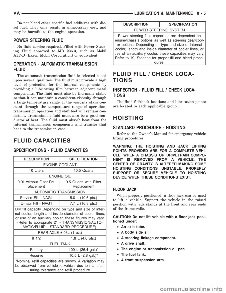
FLUID CAPACITIES
SPECIFICATIONS - FLUID CAPACITIES
DESCRIPTION SPECIFICATION
ENGINE COOLANT
10 Liters 10.5 Quarts
ENGINE OIL
9.0L without Filter Re-
placement9.5 Quarts with Filter
Replacement
AUTOMATIC TRANSMISSION
Service Fill - NAG1 5.0 L (10.6 pts.)
O-haul Fill - NAG1 7.7 L (16.3 pts.)
Dry fill capacity Depending on type and size of inter-
nal cooler, length and inside diameter of cooler lines,
or use of an auxiliary cooler, these figures may vary.
(Refer to appropriate 21 - TRANSMISSION/AUTO-
MATIC/FLUID - STANDARD PROCEDURE).
REAR AXLE .03L (1 oz.)
8 1/2 1.8 L (4.0 pts.)
FUEL TANK
Primary 100 L (26.4 gal.)*
Reserve 10.5 L (2.8 gal.)*
*Nominal refill capacities are shown. A variation may
be observed from vehicle to vehicle due to manufac-
turing tolerance and refill procedure
DESCRIPTION SPECIFICATION
POWER STEERING SYSTEM
Power steering fluid capacities are dependent on
engine/chassis options as well as steering gear/cool-
er options. Depending on type and size of internal
cooler, length and inside diameter of cooler lines, or
use of an auxiliary cooler, these capacities may vary.
Refer to 19, Steering for proper fill and bleed proce-
dures.
FLUID FILL / CHECK LOCA-
TIONS
INSPECTION - FLUID FILL / CHECK LOCA-
TIONS
The fluid fill/check locations and lubrication points
are located in each applicable group.
HOISTING
STANDARD PROCEDURE - HOISTING
Refer to the Owner's Manual for emergency vehicle
lifting procedures.
WARNING: THE HOISTING AND JACK LIFTING
POINTS PROVIDED ARE FOR A COMPLETE VEHI-
CLE. WHEN A CHASSIS OR DRIVETRAIN COMPO-
NENT IS REMOVED FROM A VEHICLE, THE
CENTER OF GRAVITY IS ALTERED MAKING SOME
HOISTING CONDITIONS UNSTABLE. PROPERLY
SUPPORT OR SECURE VEHICLE TO HOISTING
DEVICE WHEN THESE CONDITIONS EXIST.
FLOOR JACK
When properly positioned, a floor jack can be used
to lift a vehicle. Support the vehicle in the raised
position with jack stands at the front and rear ends
of the frame rails.
CAUTION: Do not lift vehicle with a floor jack posi-
tioned under:
²An axle tube.
²A body side sill.
²A steering linkage component.
²A drive shaft.
²The engine or transmission oil pan.
²The fuel tank.
²A front suspension arm.
VALUBRICATION & MAINTENANCE 0 - 5
Page 846 of 2305

(17) Take off charge air cooler together with cool-
ing loop of the steering at the radiator (Fig. 10).
(18) Remove bottom radiator trim (Fig. 10).
(19) Detach coolant hose at radiator.
(20) Detach coolant pipe together with coolant
hose at the fan shroud.
(21) Remove radiator fan shroud (Fig. 10).
INSTALLATION
(1) Install fan shroud to radiator (Fig. 10).
(2) Attach coolant pipe with hoses to fan shroud
(Fig. 10).
(3) Attach coolant hose at radiator (Fig. 10).
(4) Install bottom radiator trim (Fig. 10).
(5) Install charge air cooler along with cooling loop
of the power steering, to radiator (Fig. 10).
(6) Install radiator assembly into the rubber grom-
mets (Fig. 9).
(7) Install both right and left side radiator trim
panels (Fig. 9).
(8) Attach the transmission cooler lines (Fig. 9).
(9) Attach coolant hose to the bottom right of the
radiator (Fig. 9).
(10) Attach both power steering hydraulic lines
(Fig. 9).
(11) Connect coolant level sensor electrical connec-
tor (Fig. 9).
(12) Connect coolant hoses to the coolant reservoir,
radiator and water pump (Fig. 9).(13) Attach air intake pipe at the body.
(14) Attach charge air hose at air intake.
(15) Attach charge air hose at turbocharger.
(16) Install A/C condenser.
(17) Install front bumper.
(18) Install front end cross member.
(19) Refill power steering to proper level.
(20) Refill transmission to proper level.
(21) Close radiator drain plug and refill the cooling
system (Refer to 7 - COOLING/ENGINE/COOLANT -
STANDARD PROCEDURE).
(22) Recharge air conditioning (Refer to 24 -
HEATING & AIR CONDITIONING/PLUMBING -
STANDARD PROCEDURE).
(23) Run engine until warm and check for leaks.
RADIATOR PRESSURE CAP
DESCRIPTION
All vehicles are equipped with a pressure cap (Fig.
11). This cap releases pressure at some point within
a range of 124-145 kPa (18-21 psi). The pressure
relief point (in pounds) is engraved on top of the cap
The cooling system will operate at pressures
slightly above atmospheric pressure. This results in a
higher coolant boiling point allowing increased radi-
ator cooling capacity. The cap contains a spring-
loaded pressure relief valve. This valve opens when
system pressure reaches the release range of 124-145
kPa (18-21 psi).
A rubber gasket seals the radiator filler neck. This
is done to maintain vacuum during coolant cool-down
and to prevent leakage when system is under pres-
sure.
Fig. 10 RADIATOR AND FAN SHROUD
1 - CLIP
2 - SHROUD
3 - RADIATOR
4 - BOTTOM RADIATOR TRIM PANEL
5 - CHARGE AIR COOLER
6 - TOP RADIATOR TRIM PANEL
7 - POWER STEERING COOLER LOOP
VAENGINE 7 - 19
Page 2040 of 2305

When the outside air contains smoke, odors, high
humidity, or if rapid cooling is desired, interior air
can by recirculated by selecting the Recirculation
Mode with the mode control knob. The mode control
knob operates the recirculation door through use of a
vacuum actuator. When the Recirculation Mode is
selected, the recirculation door is closed to prevent
outside air from entering the passenger compart-
ment.
To maintain minimum evaporator temperature and
prevent evaporator freezing, an evaporator tempera-
ture sensor is used.
The A/C system is designed for the use of non-CFC,
R-134a refrigerant only and uses an expansion valve
to meter refrigerant flow to the evaporator.
DIAGNOSIS AND TESTING
A / C PERFORMANCE
The A/C system is designed to provide the passen-
ger compartment with low temperature and low
humidity air. The A/C evaporator, located in the
HVAC housing is cooled to temperatures near the
freezing point. As warm damp air passes over the
fins of the A/C evaporator, the air transfers its heat
to the refrigerant in the evaporator coils and the
moisture in the air condenses on the evaporator fins.
During periods of high heat and humidity, an A/C
system will be more effective in the Recirculation
mode (max-A/C). With the system in the Recircula-
tion mode, only air from the passenger compartment
passes through the A/C evaporator. As the passenger
compartment air dehumidifies, the A/C system per-
formance levels rise.
Humidity has an important bearing on the temper-
ature of the air delivered to the interior of the vehi-
cle. It is important to understand the effect that
humidity has on the performance of the A/C system.
When humidity is high, the A/C evaporator has to
perform a double duty. It must lower the air temper-
ature, and it must lower the temperature of the
moisture in the air that condenses on the evaporator
fins. Condensing the moisture in the air transfers
heat energy into the evaporator fins and coils. This
reduces the amount of heat the A/C evaporator can
absorb from the air. High humidity greatly reduces
the ability of the A/C evaporator to lower the temper-
ature of the air.
However, evaporator capacity used to reduce the
amount of moisture in the air is not wasted. Wring-
ing some of the moisture out of the air entering the
vehicle adds to the comfort of the passengers.
Although, an owner may expect too much from their
A/C system on humid days. A performance test is the
best way to determine whether the system is per-
forming up to design standards. This test also pro-
vides valuable clues as to the possible cause oftrouble with the A/C system. The ambient air tem-
perature in the location where the vehicle will be
tested must be a minimum of 21É C (70É F) for this
test.
A / C PERFORMANCE TEST
WARNING: Refer to the applicable warnings and
cautions for this system before performing the fol-
lowing operation (Refer to 24 - HEATING & AIR
CONDITIONING/PLUMBING - WARNINGS) and (Refer
to 24 - HEATING & AIR CONDITIONING/PLUMBING -
CAUTIONS). Failure to follow the warnings and cau-
tions could result in possible personal injury or
death.
NOTE: Very specific instructions and conditions
pertain to this procedure which are significantly dif-
ferent than procedures used in other vehicle appli-
cations. Follow each step in the order they are
presented. Do not skip steps or change conditions
from those stated or results will be adversely
affected and invalid.
NOTE: When connecting the service equipment
coupling to the line fitting, verify that the valve of
the coupling is fully closed. This will reduce the
amount of effort required to make the connection.
(1) Check for diagnostic trouble codes using a
DRBIIItscan tool. If no DTCs are found in the
engine control module (ECM), go to Step 2. If any
DTCs are found, repair as required, then proceed to
Step 2.
(2) Place the vehicle in the shade and operate the
heating-A/C system under the following conditions.
²Engine at idle at operating temperature
²All doors or windows open
²Transaxle in Neutral
²All A/C duct louvers open
²A/C-heater controls set to fresh air (NOT Recir-
culate), full cool, panel mode, high blower and with
A/C compressor engaged.
NOTE: The A/C compressor clutch is de-energized
under any of the following conditions:
²Restricted compressor (thermal fuse in the pul-
ley)
²Low pressure in the system
²Low evaporator temperature
²Hard acceleration (WOT)
²High coolant temperatures
(3) Insert a thermometer in the driver side center
panel air outlet and operate the A/C system until the
thermometer temperature stabilizes.
VAHEATING & AIR CONDITIONING 24 - 3
Page 2098 of 2305

REAR REFRIGERANT RESERVOIR
REMOVAL.............................95
INSTALLATION.........................95
REAR SUCTION LINE
DESCRIPTION.........................96
REMOVAL.............................96
INSTALLATION.........................98
REFRIGERANT LINE COUPLER
DESCRIPTION.........................98OPERATION...........................98
REMOVAL.............................99
INSTALLATION.........................99
UNDERBODY LINES
REMOVAL............................100
INSTALLATION........................102
PLUMBING
DESCRIPTION
The refrigerant lines and hoses are used to carry
the refrigerant between the various air conditioning
system components. A barrier hose design with a
nylon tube, which is sandwiched between rubber lay-
ers, is used for the R-134a air conditioning system on
this vehicle. This nylon tube helps to further contain
the R-134a refrigerant, which has a smaller molecu-
lar structure than R-12 refrigerant. The ends of the
refrigerant hoses are made from lightweight alumi-
num or steel, and commonly use braze-less fittings.
Any kinks or sharp bends in the refrigerant plumb-
ing will reduce the capacity of the entire air condi-
tioning system. Kinks and sharp bends reduce the
flow of refrigerant in the system. A good rule for the
flexible hose refrigerant lines is to keep the radius of
all bends at least ten times the diameter of the hose.
In addition, the flexible hose refrigerant lines should
be routed so they are at least 80 millimeters (3
inches) from the exhaust manifold.
OPERATION
High pressures are produced in the refrigerant sys-
tem when the air conditioning compressor is operat-
ing. Extreme care must be exercised to make sure
that each of the refrigerant system connections is
pressure-tight and leak free. It is a good practice to
inspect all flexible hose refrigerant lines at least once
a year to make sure they are in good condition and
properly routed.
The refrigerant lines and hoses cannot be repaired
and, if faulty or damaged, they must be replaced.
WARNINGS
WARNING: The A/C system contains refrigerant
under high pressure. Repairs should only be per-
formed by qualified service personnel. Severe per-
sonal injury or death may result from improper
service procedures.
WARNING: Avoid breathing the refrigerant and
refrigerant oil vapor or mist. Exposure may irritate
the eyes, nose, and/or throat. Wear eye protectionwhen servicing the A/C refrigerant system. Serious
eye injury can result from direct contact with the
refrigerant. If eye contact occurs, seek medical
attention immediately.
WARNING: Do not expose the refrigerant to open
flame. Poisonous gas is created when refrigerant is
burned. An electronic leak detector is recom-
mended. Severe personal injury or death may result
from improper service procedures.
WARNING: If accidental system discharge occurs,
ventilate the work area before resuming service.
Large amounts of refrigerant released in a closed
work area will displace the oxygen and cause suf-
focation and death.
WARNING: The evaporation rate of R-134a refriger-
ant at average temperature and altitude is extremely
high. As a result, anything that comes in contact
with the refrigerant will freeze. Always protect the
skin or delicate objects from direct contact with the
refrigerant.
WARNING: The R-134a service equipment or the
vehicle refrigerant system should not be pressure
tested or leak tested with compressed air. Some
mixtures of air and R-134a have been shown to be
combustible at elevated pressures. These mixtures
are potentially dangerous, and may result in fire or
explosion causing property damage, personal injury
or death.
WARNING: The engine cooling system is designed
to develop internal pressures of 97 to 123 kilopas-
cals (14 to 18 pounds per square inch). Do not
remove or loosen the coolant pressure cap, cylin-
der block drain plugs, radiator drain, radiator
hoses, heater hoses, or hose clamps while the
engine cooling system is hot and under pressure.
Allow the vehicle to cool for a minimum of 15 min-
utes before opening the cooling system for service.
Failure to observe this warning can result in seri-
ous burns from the heated engine coolant.
VAPLUMBING 24 - 61