2006 MERCEDES-BENZ SPRINTER radio
[x] Cancel search: radioPage 8 of 2305

TABLE OF CONTENTS - Continued
FLAME SENSOR SHORTED..............................................91
GLOW PIN OPEN.......................................................91
GLOW PIN SHORTED...................................................91
HEATER IN LOCKOUT MODE.............................................93
HEATER OVERHEATED..................................................93
SUCCESSIVE OVERHEATING............................................93
OVER VOLTAGE........................................................96
OVERHEATING SENSOR OPEN...........................................97
OVERHEATING SENSOR SHORTED.......................................97
TEMP SENSOR OPEN...................................................98
TEMP SENSOR SHORTED...............................................98
UNDER VOLTAGE......................................................99
COMMUNICATION
*NO RESPONSE FROM AIRBAG CONTROL MODULE.......................102
*NO RESPONSE FROM AUTOMATIC TEMPERATURE CONTROL..............104
*NO RESPONSE FROM CABIN HEATER MODULE..........................106
*NO RESPONSE FROM CENTRAL TIMER MODULE.........................108
*NO RESPONSE FROM CONTROLLER ANTILOCK BRAKE...................110
*NO RESPONSE FROM ENGINE CONTROL MODULE.......................112
*NO RESPONSE FROM HEATER BOOSTER MODULE.......................114
*NO RESPONSE FROM INSTRUMENT CLUSTER...........................116
*NO RESPONSE FROM RADIO..........................................118
*NO RESPONSE FROM SECURITY SYSTEM MODULE......................120
*NO RESPONSE FROM SENTRY KEY REMOTE ENTRY MODULE.............122
*NO RESPONSE FROM SHIFTER ASSEMBLY..............................124
*NO RESPONSE FROM TRANSMISSION CONTROL MODULE................126
HEATING & A/C
A/C COMPRESSOR CONTROL HIGH OR OPEN (ACTIVE)....................128
A/C COMPRESSOR CONTROL HIGH OR OPEN (STORED)...................130
A/C COMPRESSOR CONTROL SHORTED LOW (STORED)...................130
AIR OUTLET TEMP SENSOR HIGH OR OPEN (STORED)....................130
AIR OUTLET TEMP SENSOR SHORTED LOW (STORED)....................130
AUX FAN RELAY CONTROL HIGH OR OPEN (STORED).....................130
AUX FAN RELAY CONTROL SHORTED LOW (STORED).....................130
BLOWER STAGE 1 HIGH OR OPEN (STORED).............................130
BLOWER STAGE 1 SHORTED LOW (STORED).............................130
CABIN HEATER CONTROL HIGH OR OPEN (STORED)......................130
CABIN HEATER CONTROL SHORTED LOW (STORED)......................130
CIRC PUMP CONTROL HIGH OR OPEN (STORED).........................130
CIRC PUMP CONTROL SHORTED LOW (STORED).........................130
EVAP TEMP SENSOR HIGH OR OPEN (STORED)..........................130
EVAP TEMP SENSOR SHORTED LOW (STORED)..........................130
NO COMMUNICATION BUS (STORED)....................................130
NO COMMUNICATION WITH ECM (STORED)..............................130
NO COMMUNICATION WITH IC (STORED).................................130
RECIRC AIR SOLENOID CONTROL HIGH OR OPEN (STORED)...............130
RECIRC AIR SOLENOID CONTROL SHORTED LOW (STORED)...............130
REFRIG PRESS SENSOR HIGH OR OPEN (STORED).......................130
REFRIG PRESS SENSOR SHORTED LOW (STORED).......................130
WATER CYCLE VALVE CONTROL HIGH OR OPEN (STORED)................130
WATER CYCLE VALVE CONTROL SHORTED LOW (STORED)................130
iii
Page 12 of 2305

TABLE OF CONTENTS - Continued
FUSES (FUSE BLOCK NO. 2)............................................274
FUSES (FUSE BLOCK NO. 3)............................................276
FUSES (FUSE/RELAY BLOCK)...........................................278
HOOD AJAR SWITCH - BLACK...........................................278
HORN (VTSS).........................................................278
IGNITION LOCK SWITCH - BLACK........................................278
INSTRUMENT CLUSTER C1.............................................279
INSTRUMENT CLUSTER C2 - WHITE.....................................279
INTRUSION SENSOR NO. 1 - BLACK.....................................279
INTRUSION SENSOR NO. 2 - BLACK.....................................279
INTRUSION SENSOR NO. 3 - BLACK.....................................280
MASTER DOOR LOCK SWITCH..........................................280
PANIC ALARM SWITCH - BLACK.........................................280
FUSES (PDC).........................................................281
RADIO C1 - BLACK....................................................282
RADIO C2............................................................282
RECIRCULATED AIR SOLENOID VALVE...................................282
REFRIGERANT PRESSURE SENSOR.....................................282
A/C AUXILIARY FAN RELAY (RELAY BLOCK)...............................284
CIRCULATION PUMP RELAY-CABIN HEATER MODULE (RELAY BLOCK).......284
D+ RELAY NO. 2 (RELAY BLOCK)........................................284
FAN STAGE 1 RELAY (RELAY BLOCK)....................................284
OPTIONAL EQUIPMENT RELAY (RELAY BLOCK)...........................284
REMOTE KEYLESS ENTRY ANTENNA....................................284
SEAT BELT SWITCH...................................................284
SEAT BELT TENSIONER-DRIVER - YELLOW...............................285
SEAT BELT TENSIONER-PASSENGER - YELLOW...........................285
SECURITY SYSTEM MODULE C1 - BROWN...............................285
SECURITY SYSTEM MODULE C2 - LT. GREEN.............................286
SENTRY KEY REMOTE ENTRY MODULE (SKREEM)........................286
SHIFTER ASSEMBLY - BLACK...........................................286
SIREN - BLACK.......................................................286
STEERING ANGLE SENSOR............................................287
TOWING/INTRUSION SENSOR ON/OFF SWITCH...........................287
TRANSMISSION CONTROL MODULE C1 - BLACK..........................287
TRANSMISSION CONTROL MODULE C2 - BLACK..........................288
WATER CYCLE VALVE..................................................288
WINDOW DEFOGGER-LEFT REAR.......................................288
WINDOW DEFOGGER-RIGHT REAR......................................288
10.0 SCHEMATIC DIAGRAMS................................................289
10.1AIRBAG SYSTEM.................................................289
10.2COMMUNICATION................................................290
10.2.1COMMUNICATION K-LINES................................290
10.2.2CAN BUS NETWORK......................................291
10.3HEATING & A/C...................................................292
10.3.1AUTOMATIC TEMPERATURE CONTROL (ATC)................292
10.3.2CABIN HEATER MODULE (CHM)............................293
10.3.3HEATER BOOSTER MODULE (HBM).........................294
10.4INSTRUMENT CLUSTER...........................................295
vii
Page 23 of 2305

the A-pillar. The SKREEM receives radio messages
from the RKE transmitter (fob) and sends com-
mands via the RKE Interface circuit to the CTM. If
the vehicle is equipped with VTSS, the Security
System Module will be connected in series between
the SKREEM and the CTM.
Confirmation of the RKE Lock/Unlock state is
accomplished via the turn signals. When the vehicle
is locked via RKE the turn signals will flash three
times. When it is unlocked via RKE, the turn
signals will flash one time. If the vehicle has been
unlocked via RKE and no door is opened within 40
seconds, the entire vehicle will be locked again
automatically.
If a transmitter (fob) is operated more than 255
times in succession beyond the range of the receiver
(SKREEM), the RKE portion of the key will become
inoperative. In order to put it back in synchroniza-
tion it will be necessary to have ALL the other
transmitters that are used with this vehicle avail-
able and follow the following procedure:
1. Cycle the ignition on and off 2 times within 6
seconds (leave in off position).
2. Press the lock or unlock button of the disabled
transmitter within 3 seconds of turning the
ignition off.
3. Press any button (lock or unlock) 3 more times
within 6 seconds.
4. Wait 10 seconds.
5. Press any button of ALL other transmitters
belonging to this vehicle at least once within
the next 20 seconds.
For problems related to the Immobilizer function
of the SKREEM, see Service Information.
3.5.3 AUTO DOOR LOCKS
Whenever the engine is started, the CTM receives
a message to lock all doors except the drivers door.
This is accomplished through the D+ Relay. The D+
Relay is controlled by the Instrument Cluster which
receives a command from the ECM that the engine
is running. This relay supplies power to the CTM
(for auto locking), the daytime running lamps and
the rear window defogger.
3.5.4 ACCIDENT RESPONSE
The CTM is hardwired to the Airbag Control
Module through the Enhanced Accident Report
Driver circuit. Anytime the vehicle airbags are
deployed, the CTM will unlock all doors and a
9Crash9DTC will be stored in memory. The door
locks will be inoperative until that code is cleared. If
the vehicle is severly jarred, but not enough to
deploy the airbags, it is possible that the DTC could
be set and therefore the door locks would be inop-
erable. Whenever the door locks are not opera-tional, use the DRBIII and check DTC's . If the code
9ACM has unlocked the doors9appears, use the
DRBIII and erase it.
3.6 VEHICLE THEFT SECURITY SYSTEM
(VTSS)
The Security System Module (SSM) is located
under the driver's seat. The SSM communicates
with the DRBIII over the K-line. If equipped the
Vehicle Theft Security System will monitor the
following:
²door jamb switches
²hood ajar switch
²ignition switch
²interior of the vehicle for movement
²longitudinal and transverse movement of the
vehicle
²rear defogger grids for glass breakage
²trailer connector
To arm the system the hood and all of the doors
must be closed when the vehicle is locked with the
RKE transmitter or with the use of the key in the
driver door. If the key is used, it must be held in the
lock position for 2 seconds. When the system is first
activated, the hazard lamps will flash 3 times. Also
with the system armed, the Towing/Intrusion Sen-
sor On/Off Switch indicator will flash to indicate an
armed system. To disarm the system use the RKE
or the driver door lock cylinder. Unlocking and
opening one of the other doors with the system
armed will trip the vehicle theft security system.
Interior monitoring is done by the use of an
Intrusion Sensor located in the front headliner and
with one or two sensors in the ceiling of the cargo
area depending on how the vehicle is equipped.
Monitoring of the interior of the vehicle will begin
after the system has been armed for 30 seconds. The
on/off switch located on the instrument panel can be
used to turn off this feature with the ignition switch
in either the Locked/Off or ACC position. The vehi-
cle tow-monitoring feature can also be switched off
using this switch. Re-locking the vehicle a second
time will reactivate these features.
If a trailer is connected to the vehicle when the
system is armed, the SSM will sense a resistance
change on the turn signal circuits if the trailer
harness becomes disconnected and will trip the
alarm.
Tripping the vehicle theft security system will
cause the hazard lamps to flash and the siren to
sound at 30-second intervals. The siren is equipped
with it's own self-contained battery. In the event the
vehicle's battery power is disconnected the siren
will continue to sound on it's own.
10
GENERAL INFORMATION
Page 131 of 2305
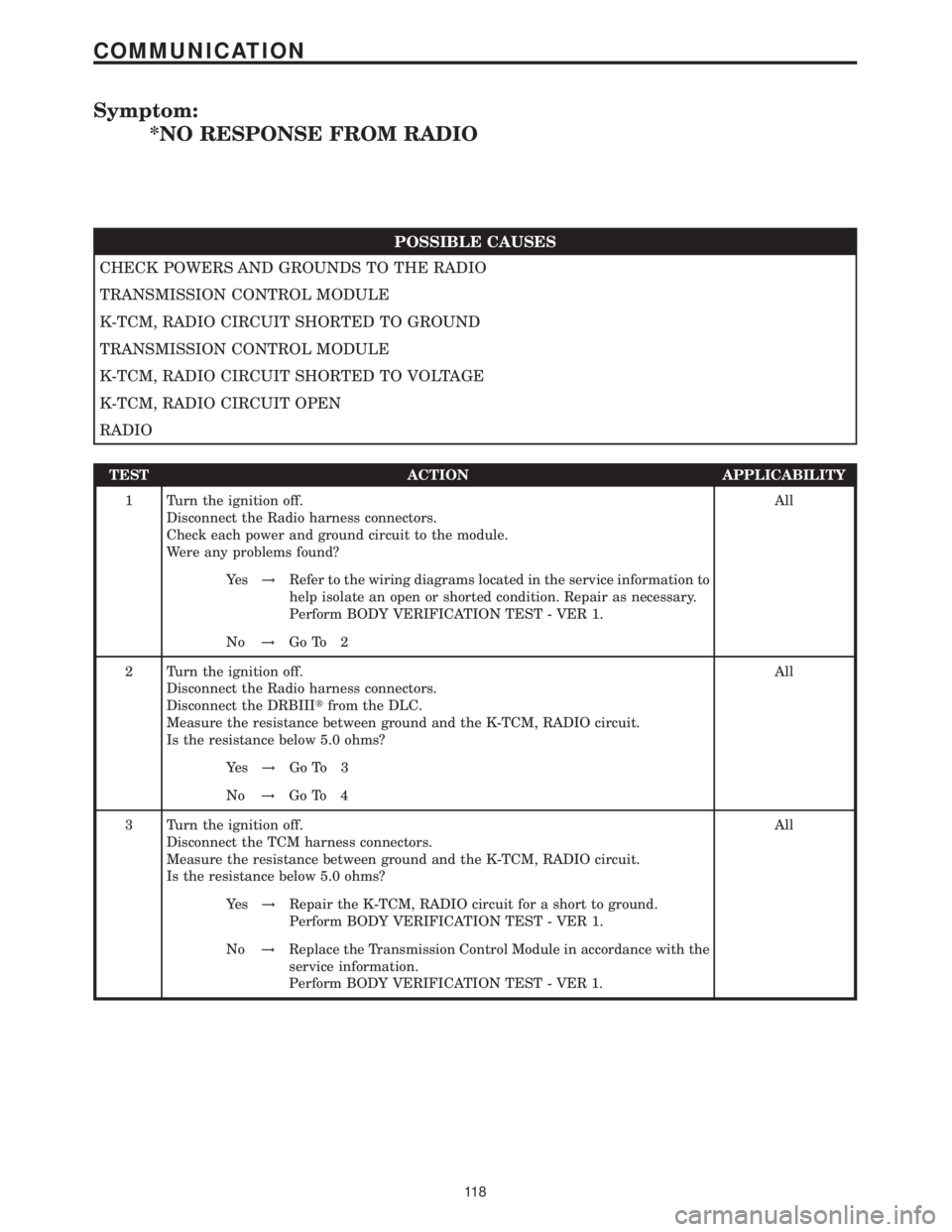
Symptom:
*NO RESPONSE FROM RADIO
POSSIBLE CAUSES
CHECK POWERS AND GROUNDS TO THE RADIO
TRANSMISSION CONTROL MODULE
K-TCM, RADIO CIRCUIT SHORTED TO GROUND
TRANSMISSION CONTROL MODULE
K-TCM, RADIO CIRCUIT SHORTED TO VOLTAGE
K-TCM, RADIO CIRCUIT OPEN
RADIO
TEST ACTION APPLICABILITY
1 Turn the ignition off.
Disconnect the Radio harness connectors.
Check each power and ground circuit to the module.
Were any problems found?All
Ye s!Refer to the wiring diagrams located in the service information to
help isolate an open or shorted condition. Repair as necessary.
Perform BODY VERIFICATION TEST - VER 1.
No!Go To 2
2 Turn the ignition off.
Disconnect the Radio harness connectors.
Disconnect the DRBIIItfrom the DLC.
Measure the resistance between ground and the K-TCM, RADIO circuit.
Is the resistance below 5.0 ohms?All
Ye s!Go To 3
No!Go To 4
3 Turn the ignition off.
Disconnect the TCM harness connectors.
Measure the resistance between ground and the K-TCM, RADIO circuit.
Is the resistance below 5.0 ohms?All
Ye s!Repair the K-TCM, RADIO circuit for a short to ground.
Perform BODY VERIFICATION TEST - VER 1.
No!Replace the Transmission Control Module in accordance with the
service information.
Perform BODY VERIFICATION TEST - VER 1.
11 8
COMMUNICATION
Page 132 of 2305
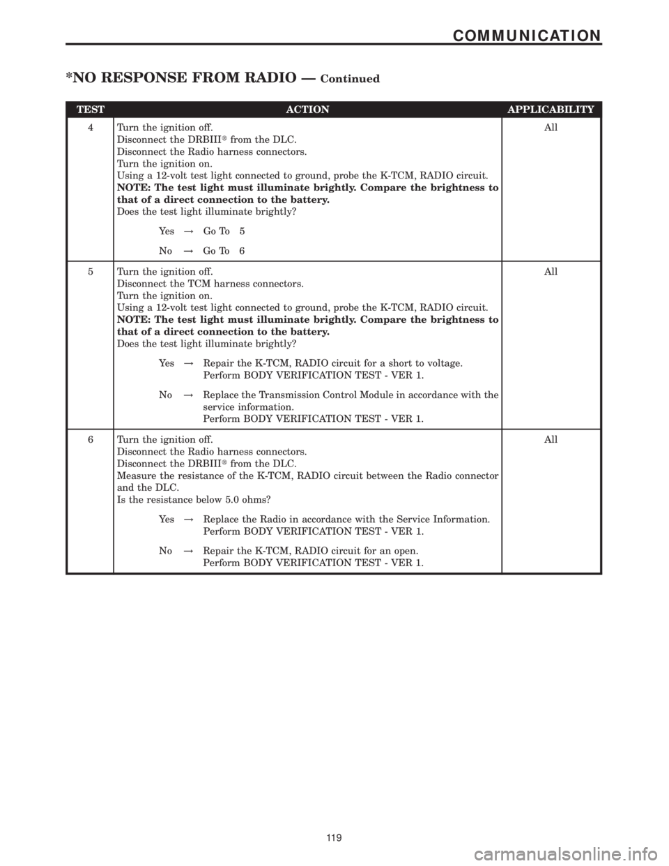
TEST ACTION APPLICABILITY
4 Turn the ignition off.
Disconnect the DRBIIItfrom the DLC.
Disconnect the Radio harness connectors.
Turn the ignition on.
Using a 12-volt test light connected to ground, probe the K-TCM, RADIO circuit.
NOTE: The test light must illuminate brightly. Compare the brightness to
that of a direct connection to the battery.
Does the test light illuminate brightly?All
Ye s!Go To 5
No!Go To 6
5 Turn the ignition off.
Disconnect the TCM harness connectors.
Turn the ignition on.
Using a 12-volt test light connected to ground, probe the K-TCM, RADIO circuit.
NOTE: The test light must illuminate brightly. Compare the brightness to
that of a direct connection to the battery.
Does the test light illuminate brightly?All
Ye s!Repair the K-TCM, RADIO circuit for a short to voltage.
Perform BODY VERIFICATION TEST - VER 1.
No!Replace the Transmission Control Module in accordance with the
service information.
Perform BODY VERIFICATION TEST - VER 1.
6 Turn the ignition off.
Disconnect the Radio harness connectors.
Disconnect the DRBIIItfrom the DLC.
Measure the resistance of the K-TCM, RADIO circuit between the Radio connector
and the DLC.
Is the resistance below 5.0 ohms?All
Ye s!Replace the Radio in accordance with the Service Information.
Perform BODY VERIFICATION TEST - VER 1.
No!Repair the K-TCM, RADIO circuit for an open.
Perform BODY VERIFICATION TEST - VER 1.
11 9
COMMUNICATION
*NO RESPONSE FROM RADIO ÐContinued
Page 139 of 2305
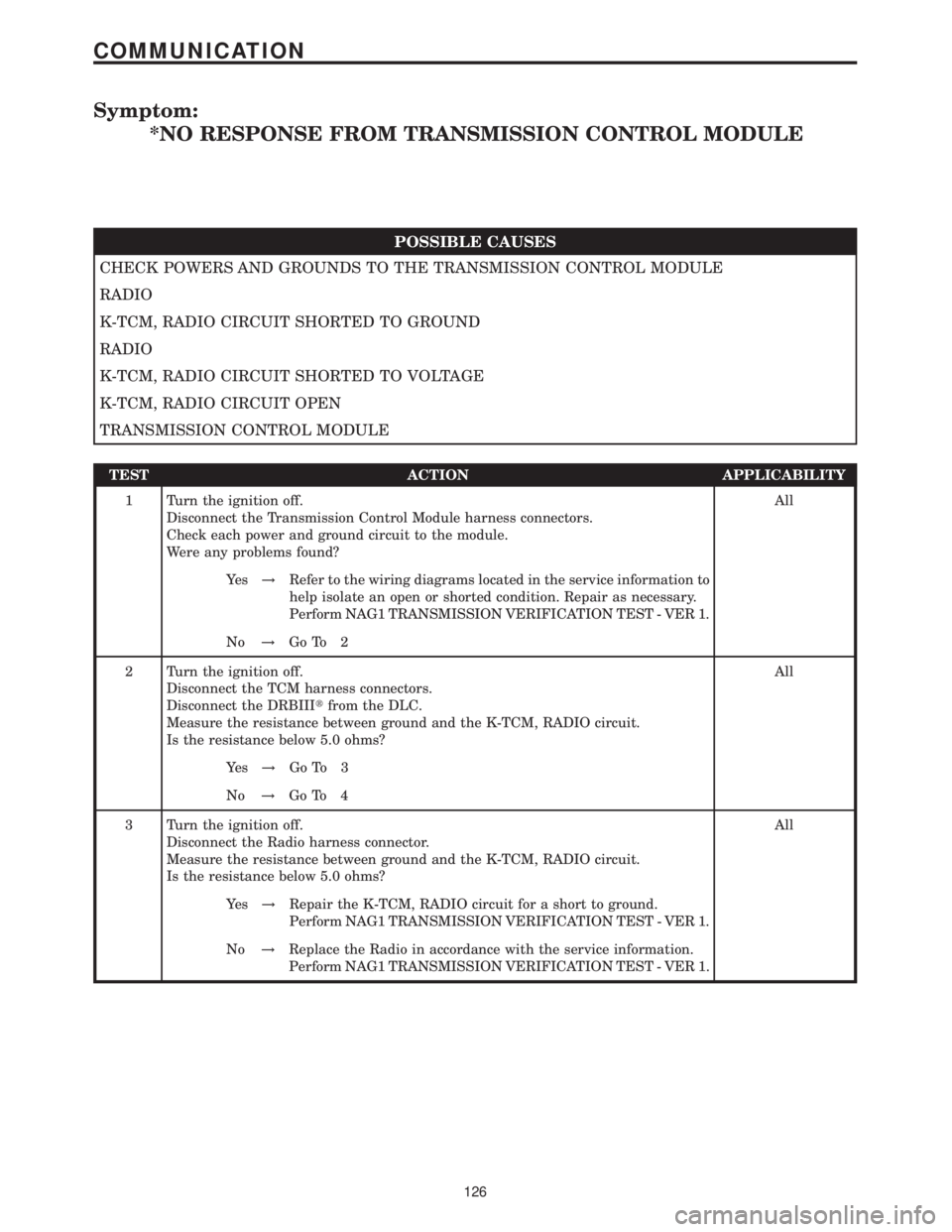
Symptom:
*NO RESPONSE FROM TRANSMISSION CONTROL MODULE
POSSIBLE CAUSES
CHECK POWERS AND GROUNDS TO THE TRANSMISSION CONTROL MODULE
RADIO
K-TCM, RADIO CIRCUIT SHORTED TO GROUND
RADIO
K-TCM, RADIO CIRCUIT SHORTED TO VOLTAGE
K-TCM, RADIO CIRCUIT OPEN
TRANSMISSION CONTROL MODULE
TEST ACTION APPLICABILITY
1 Turn the ignition off.
Disconnect the Transmission Control Module harness connectors.
Check each power and ground circuit to the module.
Were any problems found?All
Ye s!Refer to the wiring diagrams located in the service information to
help isolate an open or shorted condition. Repair as necessary.
Perform NAG1 TRANSMISSION VERIFICATION TEST - VER 1.
No!Go To 2
2 Turn the ignition off.
Disconnect the TCM harness connectors.
Disconnect the DRBIIItfrom the DLC.
Measure the resistance between ground and the K-TCM, RADIO circuit.
Is the resistance below 5.0 ohms?All
Ye s!Go To 3
No!Go To 4
3 Turn the ignition off.
Disconnect the Radio harness connector.
Measure the resistance between ground and the K-TCM, RADIO circuit.
Is the resistance below 5.0 ohms?All
Ye s!Repair the K-TCM, RADIO circuit for a short to ground.
Perform NAG1 TRANSMISSION VERIFICATION TEST - VER 1.
No!Replace the Radio in accordance with the service information.
Perform NAG1 TRANSMISSION VERIFICATION TEST - VER 1.
126
COMMUNICATION
Page 140 of 2305
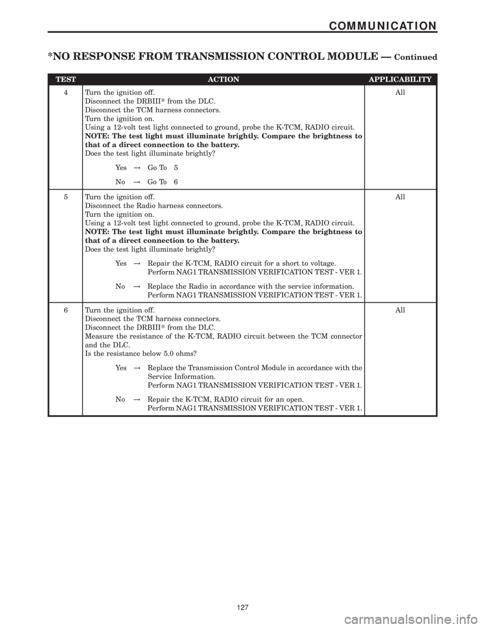
TEST ACTION APPLICABILITY
4 Turn the ignition off.
Disconnect the DRBIIItfrom the DLC.
Disconnect the TCM harness connectors.
Turn the ignition on.
Using a 12-volt test light connected to ground, probe the K-TCM, RADIO circuit.
NOTE: The test light must illuminate brightly. Compare the brightness to
that of a direct connection to the battery.
Does the test light illuminate brightly?All
Ye s!Go To 5
No!Go To 6
5 Turn the ignition off.
Disconnect the Radio harness connectors.
Turn the ignition on.
Using a 12-volt test light connected to ground, probe the K-TCM, RADIO circuit.
NOTE: The test light must illuminate brightly. Compare the brightness to
that of a direct connection to the battery.
Does the test light illuminate brightly?All
Ye s!Repair the K-TCM, RADIO circuit for a short to voltage.
Perform NAG1 TRANSMISSION VERIFICATION TEST - VER 1.
No!Replace the Radio in accordance with the service information.
Perform NAG1 TRANSMISSION VERIFICATION TEST - VER 1.
6 Turn the ignition off.
Disconnect the TCM harness connectors.
Disconnect the DRBIIItfrom the DLC.
Measure the resistance of the K-TCM, RADIO circuit between the TCM connector
and the DLC.
Is the resistance below 5.0 ohms?All
Ye s!Replace the Transmission Control Module in accordance with the
Service Information.
Perform NAG1 TRANSMISSION VERIFICATION TEST - VER 1.
No!Repair the K-TCM, RADIO circuit for an open.
Perform NAG1 TRANSMISSION VERIFICATION TEST - VER 1.
127
COMMUNICATION
*NO RESPONSE FROM TRANSMISSION CONTROL MODULE ÐContinued
Page 276 of 2305
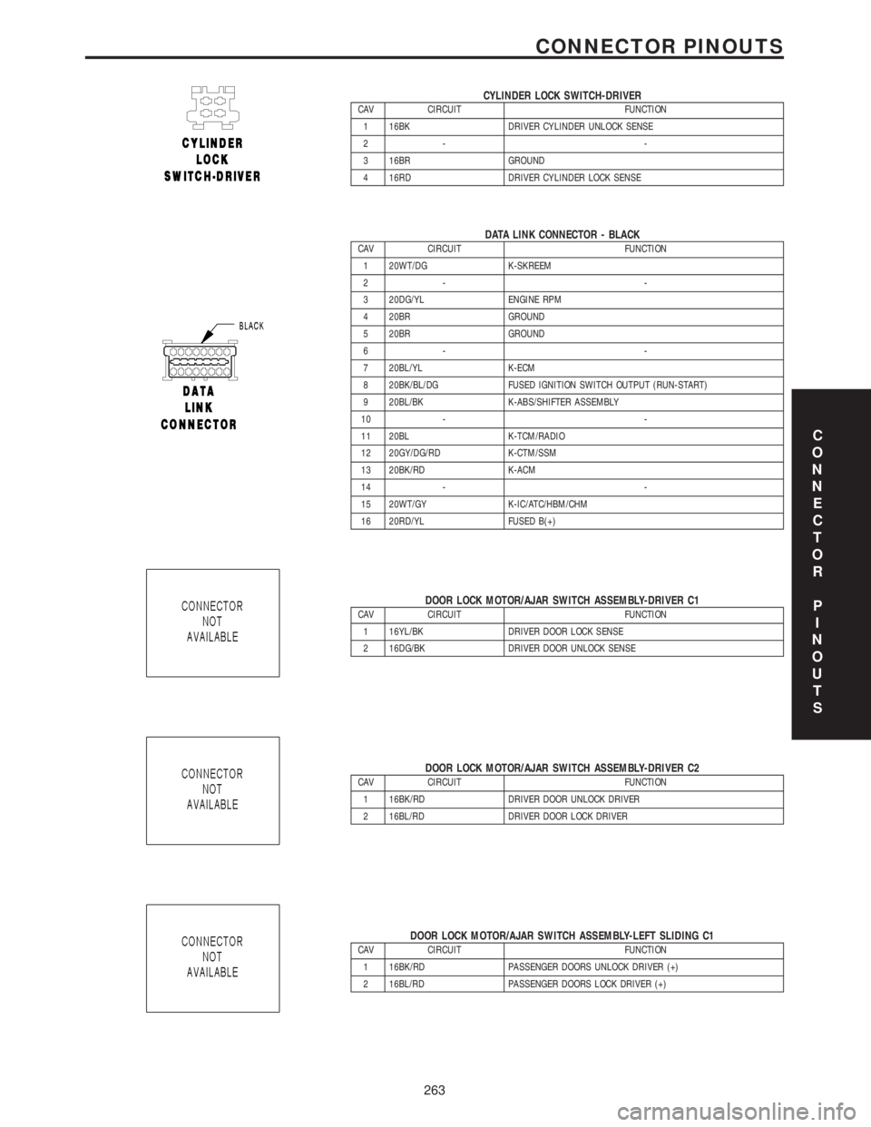
CYLINDER LOCK SWITCH-DRIVERCAV CIRCUIT FUNCTION
1 16BK DRIVER CYLINDER UNLOCK SENSE
2- -
3 16BR GROUND
4 16RD DRIVER CYLINDER LOCK SENSE
DATA LINK CONNECTOR - BLACKCAV CIRCUIT FUNCTION
1 20WT/DG K-SKREEM
2- -
3 20DG/YL ENGINE RPM
4 20BR GROUND
5 20BR GROUND
6- -
7 20BL/YL K-ECM
8 20BK/BL/DG FUSED IGNITION SWITCH OUTPUT (RUN-START)
9 20BL/BK K-ABS/SHIFTER ASSEMBLY
10 - -
11 20BL K-TCM/RADIO
12 20GY/DG/RD K-CTM/SSM
13 20BK/RD K-ACM
14 - -
15 20WT/GY K-IC/ATC/HBM/CHM
16 20RD/YL FUSED B(+)
DOOR LOCK MOTOR/AJAR SWITCH ASSEMBLY-DRIVER C1CAV CIRCUIT FUNCTION
1 16YL/BK DRIVER DOOR LOCK SENSE
2 16DG/BK DRIVER DOOR UNLOCK SENSE
DOOR LOCK MOTOR/AJAR SWITCH ASSEMBLY-DRIVER C2CAV CIRCUIT FUNCTION
1 16BK/RD DRIVER DOOR UNLOCK DRIVER
2 16BL/RD DRIVER DOOR LOCK DRIVER
DOOR LOCK MOTOR/AJAR SWITCH ASSEMBLY-LEFT SLIDING C1CAV CIRCUIT FUNCTION
1 16BK/RD PASSENGER DOORS UNLOCK DRIVER (+)
2 16BL/RD PASSENGER DOORS LOCK DRIVER (+)
C
O
N
N
E
C
T
O
R
P
I
N
O
U
T
S
263
CONNECTOR PINOUTS