2006 MERCEDES-BENZ SPRINTER reset
[x] Cancel search: resetPage 108 of 2305
TEST ACTION APPLICABILITY
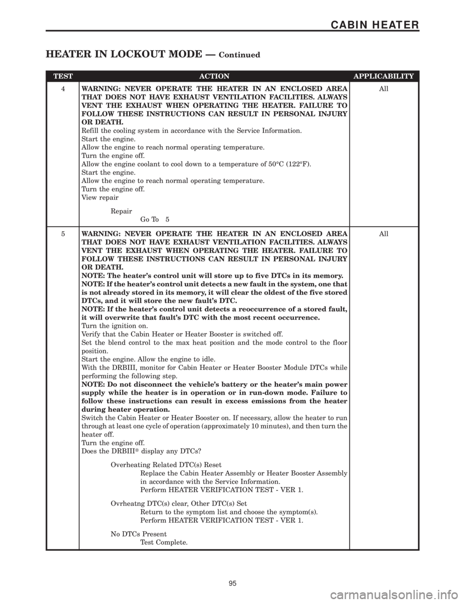
4WARNING: NEVER OPERATE THE HEATER IN AN ENCLOSED AREA
THAT DOES NOT HAVE EXHAUST VENTILATION FACILITIES. ALWAYS
VENT THE EXHAUST WHEN OPERATING THE HEATER. FAILURE TO
FOLLOW THESE INSTRUCTIONS CAN RESULT IN PERSONAL INJURY
OR DEATH.
Refill the cooling system in accordance with the Service Information.
Start the engine.
Allow the engine to reach normal operating temperature.
Turn the engine off.
Allow the engine coolant to cool down to a temperature of 50ÉC (122ÉF).
Start the engine.
Allow the engine to reach normal operating temperature.
Turn the engine off.
View repairAll
Repair
Go To 5
5WARNING: NEVER OPERATE THE HEATER IN AN ENCLOSED AREA
THAT DOES NOT HAVE EXHAUST VENTILATION FACILITIES. ALWAYS
VENT THE EXHAUST WHEN OPERATING THE HEATER. FAILURE TO
FOLLOW THESE INSTRUCTIONS CAN RESULT IN PERSONAL INJURY
OR DEATH.
NOTE: The heater's control unit will store up to five DTCs in its memory.
NOTE: If the heater's control unit detects a new fault in the system, one that
is not already stored in its memory, it will clear the oldest of the five stored
DTCs, and it will store the new fault's DTC.
NOTE: If the heater's control unit detects a reoccurrence of a stored fault,
it will overwrite that fault's DTC with the most recent occurrence.
Turn the ignition on.
Verify that the Cabin Heater or Heater Booster is switched off.
Set the blend control to the max heat position and the mode control to the floor
position.
Start the engine. Allow the engine to idle.
With the DRBIII, monitor for Cabin Heater or Heater Booster Module DTCs while
performing the following step.
NOTE: Do not disconnect the vehicle's battery or the heater's main power
supply while the heater is in operation or in run-down mode. Failure to
follow these instructions can result in excess emissions from the heater
during heater operation.
Switch the Cabin Heater or Heater Booster on. If necessary, allow the heater to run
through at least one cycle of operation (approximately 10 minutes), and then turn the
heater off.
Turn the engine off.
Does the DRBIIItdisplay any DTCs?All
Overheating Related DTC(s) Reset
Replace the Cabin Heater Assembly or Heater Booster Assembly
in accordance with the Service Information.
Perform HEATER VERIFICATION TEST - VER 1.
Ovrheatng DTC(s) clear, Other DTC(s) Set
Return to the symptom list and choose the symptom(s).
Perform HEATER VERIFICATION TEST - VER 1.
No DTCs Present
Test Complete.
95
CABIN HEATER
HEATER IN LOCKOUT MODE ÐContinued
Page 201 of 2305
Symptom:
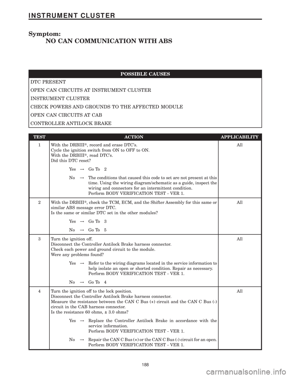
NO CAN COMMUNICATION WITH ABS
POSSIBLE CAUSES
DTC PRESENT
OPEN CAN CIRCUITS AT INSTRUMENT CLUSTER
INSTRUMENT CLUSTER
CHECK POWERS AND GROUNDS TO THE AFFECTED MODULE
OPEN CAN CIRCUITS AT CAB
CONTROLLER ANTILOCK BRAKE
TEST ACTION APPLICABILITY
1 With the DRBIIIt, record and erase DTC's.
Cycle the ignition switch from ON to OFF to ON.
With the DRBIIIt, read DTC's.
Did this DTC reset?All
Ye s!Go To 2
No!The conditions that caused this code to set are not present at this
time. Using the wiring diagram/schematic as a guide, inspect the
wiring and connectors for an intermittent condition.
Perform BODY VERIFICATION TEST - VER 1.
2 With the DRBIIIt, check the TCM, ECM, and the Shifter Assembly for this same or
similar ABS message error DTC.
Is the same or similar DTC set in the other modules?All
Ye s!Go To 3
No!Go To 5
3 Turn the ignition off.
Disconnect the Controller Antilock Brake harness connector.
Check each power and ground circuit to the module.
Were any problems found?All
Ye s!Refer to the wiring diagrams located in the service information to
help isolate an open or shorted condition. Repair as necessary.
Perform BODY VERIFICATION TEST - VER 1.
No!Go To 4
4 Turn the ignition off to the lock position.
Disconnect the Controller Antilock Brake harness connector.
Measure the resistance between the CAN C Bus (+) circuit and the CAN C Bus (-)
circuit in the CAB harness connector.
Is the resistance 60 ohms, 3.0 ohms?All
Ye s!Replace the Controller Antilock Brake in accordance with the
service information.
Perform BODY VERIFICATION TEST - VER 1.
No!Repair the CAN C Bus (+) or the CAN C Bus (-) circuit for an open.
Perform BODY VERIFICATION TEST - VER 1.
188
INSTRUMENT CLUSTER
Page 203 of 2305
Symptom:
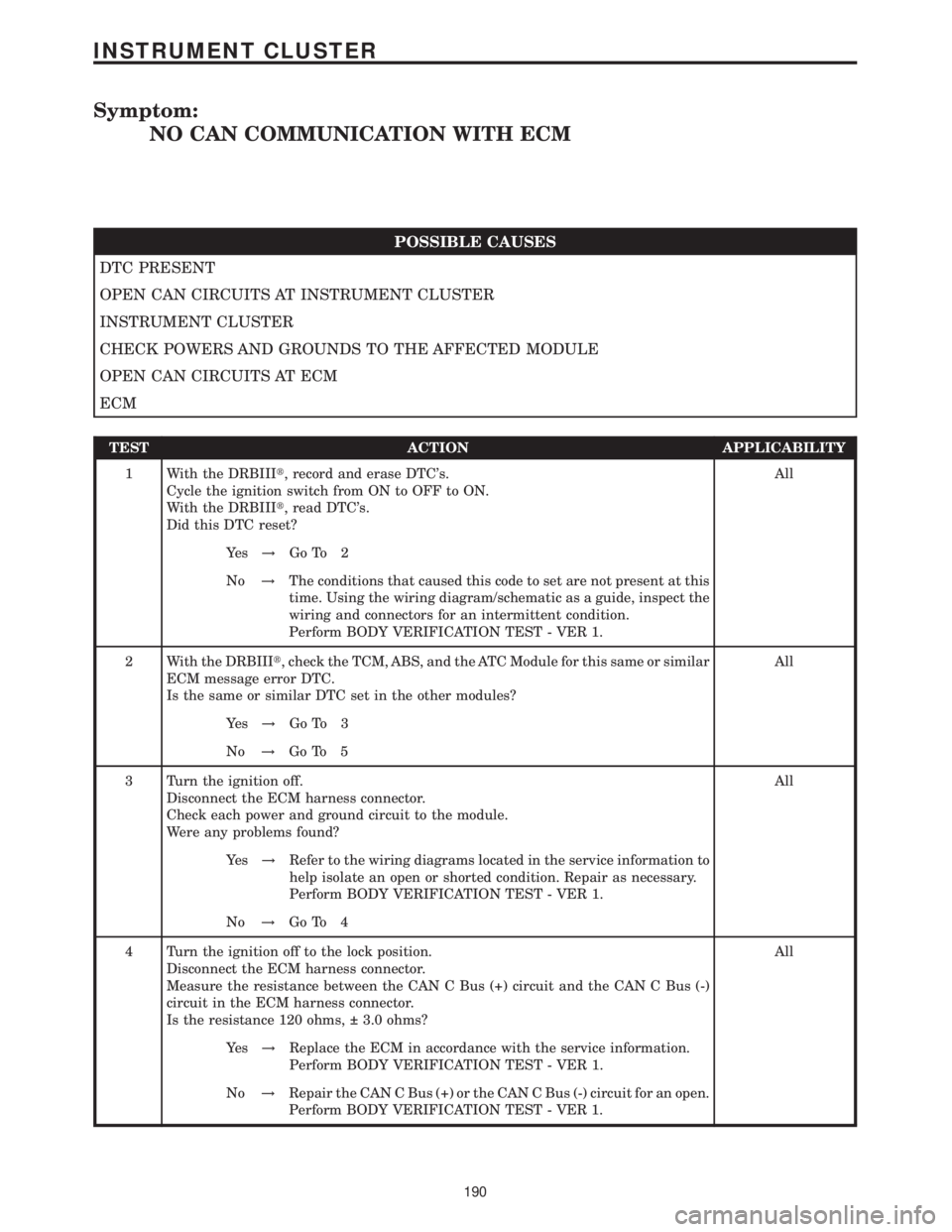
NO CAN COMMUNICATION WITH ECM
POSSIBLE CAUSES
DTC PRESENT
OPEN CAN CIRCUITS AT INSTRUMENT CLUSTER
INSTRUMENT CLUSTER
CHECK POWERS AND GROUNDS TO THE AFFECTED MODULE
OPEN CAN CIRCUITS AT ECM
ECM
TEST ACTION APPLICABILITY
1 With the DRBIIIt, record and erase DTC's.
Cycle the ignition switch from ON to OFF to ON.
With the DRBIIIt, read DTC's.
Did this DTC reset?All
Ye s!Go To 2
No!The conditions that caused this code to set are not present at this
time. Using the wiring diagram/schematic as a guide, inspect the
wiring and connectors for an intermittent condition.
Perform BODY VERIFICATION TEST - VER 1.
2 With the DRBIIIt, check the TCM, ABS, and the ATC Module for this same or similar
ECM message error DTC.
Is the same or similar DTC set in the other modules?All
Ye s!Go To 3
No!Go To 5
3 Turn the ignition off.
Disconnect the ECM harness connector.
Check each power and ground circuit to the module.
Were any problems found?All
Ye s!Refer to the wiring diagrams located in the service information to
help isolate an open or shorted condition. Repair as necessary.
Perform BODY VERIFICATION TEST - VER 1.
No!Go To 4
4 Turn the ignition off to the lock position.
Disconnect the ECM harness connector.
Measure the resistance between the CAN C Bus (+) circuit and the CAN C Bus (-)
circuit in the ECM harness connector.
Is the resistance 120 ohms, 3.0 ohms?All
Ye s!Replace the ECM in accordance with the service information.
Perform BODY VERIFICATION TEST - VER 1.
No!Repair the CAN C Bus (+) or the CAN C Bus (-) circuit for an open.
Perform BODY VERIFICATION TEST - VER 1.
190
INSTRUMENT CLUSTER
Page 205 of 2305
Symptom:
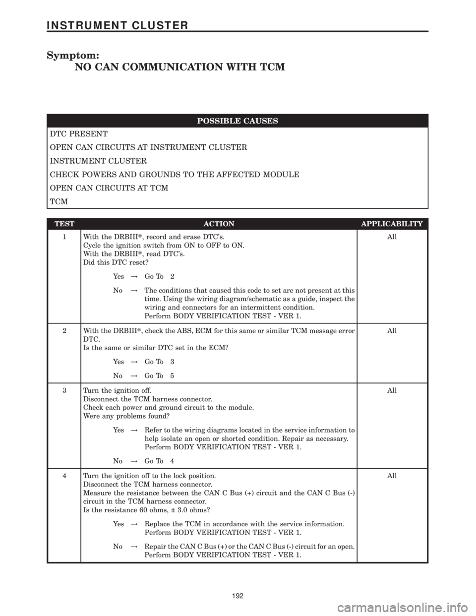
NO CAN COMMUNICATION WITH TCM
POSSIBLE CAUSES
DTC PRESENT
OPEN CAN CIRCUITS AT INSTRUMENT CLUSTER
INSTRUMENT CLUSTER
CHECK POWERS AND GROUNDS TO THE AFFECTED MODULE
OPEN CAN CIRCUITS AT TCM
TCM
TEST ACTION APPLICABILITY
1 With the DRBIIIt, record and erase DTC's.
Cycle the ignition switch from ON to OFF to ON.
With the DRBIIIt, read DTC's.
Did this DTC reset?All
Ye s!Go To 2
No!The conditions that caused this code to set are not present at this
time. Using the wiring diagram/schematic as a guide, inspect the
wiring and connectors for an intermittent condition.
Perform BODY VERIFICATION TEST - VER 1.
2 With the DRBIIIt, check the ABS, ECM for this same or similar TCM message error
DTC.
Is the same or similar DTC set in the ECM?All
Ye s!Go To 3
No!Go To 5
3 Turn the ignition off.
Disconnect the TCM harness connector.
Check each power and ground circuit to the module.
Were any problems found?All
Ye s!Refer to the wiring diagrams located in the service information to
help isolate an open or shorted condition. Repair as necessary.
Perform BODY VERIFICATION TEST - VER 1.
No!Go To 4
4 Turn the ignition off to the lock position.
Disconnect the TCM harness connector.
Measure the resistance between the CAN C Bus (+) circuit and the CAN C Bus (-)
circuit in the TCM harness connector.
Is the resistance 60 ohms, 3.0 ohms?All
Ye s!Replace the TCM in accordance with the service information.
Perform BODY VERIFICATION TEST - VER 1.
No!Repair the CAN C Bus (+) or the CAN C Bus (-) circuit for an open.
Perform BODY VERIFICATION TEST - VER 1.
192
INSTRUMENT CLUSTER
Page 324 of 2305

²Four Wheel Speed Sensors/Tone Wheel assem-
blies
²ABS warning indicator
²TCS (ASR) event indicator
²TCS (ASR) warning indicator
²Steering Angle Sensor
²Lateral Acceleration/Yaw Rate Sensor
²Brake Pressure Sensor
²ESP event indicator
²Brake Fluid Level switch
²Brake Switch (BS)
²Brake Lamp Switch (BLS)
²TCS Switch (TCSS)
²K - ABS
²CAN C Bus
²Fuses, grounds, and wiring
3.7.1 ABS AND TCS (ASR) INDICATORS
This system is equipped with an ABS warning
indicator, TCS (ASR) warning indicator, and TCS
(ASR) event indicator to alert the driver of a
malfunction/event it has detected. The CAB can
request the illumination of the ABS warning indi-
cator, TCS (ASR) warning indicator, and TCS (ASR)
event indicator via CAN C BUS. The CAB controls
the ABS warning indicator by:
²Light steady during an initial test at the begin-
ning of an ignition cycle to function as a bulb
check
²Light steady when a system malfunction exists
(DTC)
²Light steady - If you have not met the speed
required to reset/retest the ABS components
The Instrument Cluster (IC) controls the indica-
tors. The Instrument Cluster transmits a message
over the CAN C Bus relating to diagnostics and
current lamp status for the ABS and TCS (ASR)
indicators. The CAB can control the operation of
TCS warning and TCS event indicators by:
²Both light steady with engine off and both go out
with engine running
²TCS warning indicator lights steady when a TCS
malfunction exists
²TCS event indicator will flash when TCS is in an
active event
3.7.2 CONTROLLER ANTILOCK BRAKE
(CAB)
The CAB is mounted directly to the Hydraulic
Control Unit (HCU) that includes a microprocessor
and twelve solenoids that control valves that con-trol brake pressure during antilock braking or trac-
tion control events. The CAB also has circuits that
monitor the following:
²Double brake switch outputs are monitored to
determine whether or not to prepare for possible
ABS braking
²Wheel Speed Sensors are monitored to determine
when a wheel is tending to lock up. The CAB will
operate the valves in the HCU to control braking
pressure during ABS braking
²Detect ABS system related problems and take
diagnostic action
²Able to execute self-tests and output control com-
mands
When equipped with Electronic Stability (ESP),
the CAB also monitors the following:
²The ESP looks at the Steering Angle Sensor value
and monitors the speed of the inner and outer
wheels to ensure that the values are plausible.
The Steering Angle Sensor also monitors the
speed that the steering wheel is turned.
²The Lateral Acceleration/Yaw Rate Sensor is con-
tained in one unit. The sensor measures side to
side (lateral) motion and rotational motion (how
fast the vehicle is turning).
²The ESP uses data from the Brake Pressure
Sensor to analyze how hard and fast that the
driver wants to brake.
3.7.3 HYDRAULIC CONTROL UNIT (HCU)
The HCU on the Bosch 5.7 has an integral valve
body for controlling the front and rear brakes.
Within the HCU are inlet, outlet, and shuttle
valves, to release brake pressure as required to
avoid wheel lockup, keeping the wheels rolling, and
maintain optimum deceleration with stability. The
Pump Motor is attached to the HCU which works
with the ABS and TCS and is controlled by the
CAB. The primary function is to provide extra
amount of fluid when needed.
3.7.4 SWITCHES/SENSORS
BRAKE SWITCH (BS):This switch prepares the
CAB for a possible antilock event. The CAB uses an
output state voltage from the BS when the brake
pedal is either released/depressed. The Fused Igni-
tion Switch Output circuit supplies 12 volts to the
BS. A released brake pedal will close the BS circuit
and the BS Output circuit supplies 12 volts to the
CAB. When the driver depresses the brake pedal,
the BS Output circuit voltage drops to 0 volts and
the CAB senses the brake pedal state. This tells the
CAB what position the brake pedal is currently in to
make an ABS event possible. When using the
DRBIIItin Inputs/Outputs, the BS and BLS will
3
GENERAL INFORMATION
Page 331 of 2305
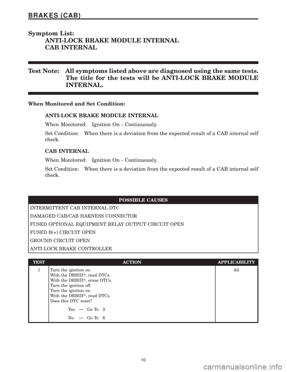
Symptom List:
ANTI-LOCK BRAKE MODULE INTERNAL
CAB INTERNAL
Test Note: All symptoms listed above are diagnosed using the same tests.
The title for the tests will be ANTI-LOCK BRAKE MODULE
INTERNAL.
When Monitored and Set Condition:
ANTI-LOCK BRAKE MODULE INTERNAL
When Monitored: Ignition On - Continuously.
Set Condition: When there is a deviation from the expected result of a CAB internal self
check.
CAB INTERNAL
When Monitored: Ignition On - Continuously.
Set Condition: When there is a deviation from the expected result of a CAB internal self
check.
POSSIBLE CAUSES
INTERMITTENT CAB INTERNAL DTC
DAMAGED CAB/CAB HARNESS CONNECTOR
FUSED OPTIONAL EQUIPMENT RELAY OUTPUT CIRCUIT OPEN
FUSED B(+) CIRCUIT OPEN
GROUND CIRCUIT OPEN
ANTI-LOCK BRAKE CONTROLLER
TEST ACTION APPLICABILITY
1 Turn the ignition on.
With the DRBIIIt, read DTCs.
With the DRBIIIt, erase DTCs.
Turn the ignition off.
Turn the ignition on.
With the DRBIIIt, read DTCs.
Does this DTC reset?All
Ye s!Go To 2
No!Go To 6
10
BRAKES (CAB)
Page 336 of 2305

Symptom:
BRAKE PRESSURE SENSOR CIRCUIT
POSSIBLE CAUSES
BRAKE PRESSURE SENSOR CIRCUIT INTERMITTENT DTC
BRAKE PRESSURE SENSOR CIRCUIT SHORT TO VOLTAGE
BRAKE PRESSURE SENSOR CIRCUIT SHORT TO GROUND
BRAKE PRESSURE SENSOR CIRCUIT OPEN
BRAKE PRESSURE SENSOR
ANTI-LOCK BRAKE CONTROLLER
TEST ACTION APPLICABILITY
1 Turn the ignition off.
Turn the ignition on.
With the DRBIIIt, read DTCs. Record DTC information.
NOTE: If a system undervoltage or overvoltage DTC is set along with this
DTC, diagnose the system voltage DTC first.
NOTE: Before continuing, make sure that the Brake Lamp switch is ad-
justed correctly and functioning properly. Adjust or replace the switch as
necessary in accordance with the Service Information.
With the DRBIIIt, erase DTCs.
Road test the vehicle and perform several braking maneuvers.
With the DRBIIIt, read DTCs.
Does this DTC reset?All
Ye s!Go To 2
No!Go To 6
2 Turn the ignition off.
Disconnect the Brake Pressure Sensor harness connector.
Disconnect the CAB harness connector.
Turn the ignition on.
Measure the voltage of the Brake Pressure Sensor signal circuit.
Measure the voltage of the Brake Pressure Sensor ground circuit.
Measure the voltage of the Brake Pressure Sensor 5 volt supply circuit.
Is there voltage present on any of the circuits?All
Ye s!Repair the Brake Pressure Sensor circuit(s) for a short to voltage.
No!Go To 3
3 Turn the ignition off.
Disconnect the Brake Pressure Sensor harness connector.
Disconnect the CAB harness connector.
Measure the resistance between ground and the Brake Pressure Sensor signal
circuit.
Measure the resistance between ground and the Brake Pressure Sensor 5 volt supply
circuit.
Is the resistance below 5.0 ohms for either circuit?All
Ye s!Repair the Brake Pressure Sensor circuit(s) for a short to ground.
No!Go To 4
15
BRAKES (CAB)
Page 337 of 2305

TEST ACTION APPLICABILITY
4 Turn the ignition off.
Disconnect the Brake Pressure Sensor harness connector.
Disconnect the CAB harness connector.
Measure the resistance of the Brake Pressure Sensor signal circuit.
Measure the resistance of the Brake Pressure Sensor ground circuit.
Measure the resistance of the Brake Pressure Sensor 5 volt supply circuit.
Is the resistance above 5.0 ohms for any of the circuits?All
Ye s!Repair the Brake Pressure Sensor circuit(s) for an open
No!Go To 5
5 Turn the ignition off.
Disconnect the Brake Pressure Sensor harness connector.
Inspect the harness and connectors related to this circuit. If any problems are found,
repair as necessary.
If no problems are found, replace the Brake Pressure Sensor in accordance with the
Service Information.
With the DRBIIIt, clear DTCs.
Road test the vehicle and perform several braking maneuvers.
With the DRBIIIt, read DTCs.
Does this DTC reset?All
Ye s!Replace the CAB in accordance with the Service Information.
No!Test Complete.
6 The condition that set this DTC is not present at this time.
Monitor the DRBIIItwhile wiggle testing the related harness and connectors. Look
for any related parameters to change or for the DTC to reset.
Inspect the related harness and connectors.
Look for any chafed, pierced, pinched, or partially broken wires.
Look for broken, bent, pushed out, or corroded terminals.
Were any problems found?All
Ye s!Repair as necessary.
No!Test Complete.
16
BRAKES (CAB)
BRAKE PRESSURE SENSOR CIRCUIT ÐContinued