2006 MERCEDES-BENZ SPRINTER length
[x] Cancel search: lengthPage 103 of 2305
TEST ACTION APPLICABILITY
3WARNING: NEVER OPERATE THE HEATER IN AN ENCLOSED AREA
THAT DOES NOT HAVE EXHAUST VENTILATION FACILITIES. ALWAYS
VENT THE EXHAUST WHEN OPERATING THE HEATER. FAILURE TO
FOLLOW THESE INSTRUCTIONS CAN RESULT IN PERSONAL INJURY
OR DEATH.
WARNING: ALLOW THE HEATER ASSEMBLY TO COOL BEFORE PER-
FORMING A COMPONENT INSPECTION/REPAIR/REPLACEMENT. FAIL-
URE TO FOLLOW THESE INSTRUCTIONS CAN RESULT IN PERSONAL
INJURY OR DEATH.
Turn the ignition off.
Disconnect the fuel line from the fuel outlet side of the Dosing Pump.
Using a suitable length of fuel line, connect one end to the fuel outlet side of the
Dosing Pump and place the other end in a suitable container.
Turn the ignition on.
CAUTION: For the result of this test to be valid, the vehicle's battery must
be fully charged.
CAUTION: For the result of the Dosing Pump OUTPUT test to be valid,
actuate Dosing Pump PRIME if the heater's fuel supply line was drained &
then not primed. Remove any fuel in the container before performing the
Dosing Pump OUTPUT test.
If the heater's fuel supply line was drained and then not primed, with the DRBIIIt
in System Tests, actuate Dosing Pump PRIME. Otherwise, proceed to the next step
of this procedure.
With the DRBIIItin System Tests, select Dosing Pump OUTPUT. Allow the Dosing
Pump Output test to run the full 90 seconds. When the Dosing Pump Output test is
complete, measure the amount of fuel in the container.
Does the dosing pump output 422 - 636 cc (14.26 - 21.5 oz) in 90 seconds?All
Ye s!Go To 4
No!Replace the Dosing Pump in accordance with the Service Infor-
mation.
Perform HEATER VERIFICATION TEST - VER 1.
4WARNING: NEVER OPERATE THE HEATER IN AN ENCLOSED AREA
THAT DOES NOT HAVE EXHAUST VENTILATION FACILITIES. ALWAYS
VENT THE EXHAUST WHEN OPERATING THE HEATER. FAILURE TO
FOLLOW THESE INSTRUCTIONS CAN RESULT IN PERSONAL INJURY
OR DEATH.
WARNING: ALLOW THE HEATER ASSEMBLY TO COOL BEFORE PER-
FORMING A COMPONENT INSPECTION/REPAIR/REPLACEMENT. FAIL-
URE TO FOLLOW THESE INSTRUCTIONS CAN RESULT IN PERSONAL
INJURY OR DEATH.
Turn the ignition off.
Inspect the heater's air intake pipe and exhaust pipe for restrictions and obstruc-
tions.
Is the heater's air intake pipe and exhaust pipe Ok?All
Ye s!Replace the Cabin Heater Assembly or Heater Booster Assembly
in accordance with the Service Information.
Perform HEATER VERIFICATION TEST - VER 1.
No!Repair the heater's air intake/exhaust as necessary in accordance
with the Service Information.
Perform HEATER VERIFICATION TEST - VER 1.
90
CABIN HEATER
FLAME OUT ÐContinued
Page 720 of 2305
Do not blend other specific fuel additives with die-
sel fuel. They only result in unnecessary cost, and
may be harmful to the engine operation.
POWER STEERING FLUID
No fluid service required. Filled with Power Steer-
ing Fluid approved to MB 236.3, such as Mobil
ATF-D (Exxon Mobil Corporation) or equivalent.
OPERATION - AUTOMATIC TRANSMISSION
FLUID
The automatic transmission fluid is selected based
upon several qualities. The fluid must provide a high
level of protection for the internal components by
providing a lubricating film between adjacent metal
components. The fluid must also be thermally stable
so that it can maintain a consistent viscosity through
a large temperature range. If the viscosity stays con-
stant through the temperature range of operation,
transmission operation and shift feel will remain con-
sistent. Transmission fluid must also be a good con-
ductor of heat. The fluid must absorb heat from the
internal transmission components and transfer that
heat to the transmission case.
FLUID CAPACITIES
SPECIFICATIONS - FLUID CAPACITIES
DESCRIPTION SPECIFICATION
ENGINE COOLANT
10 Liters 10.5 Quarts
ENGINE OIL
9.0L without Filter Re-
placement9.5 Quarts with Filter
Replacement
AUTOMATIC TRANSMISSION
Service Fill - NAG1 5.0 L (10.6 pts.)
O-haul Fill - NAG1 7.7 L (16.3 pts.)
Dry fill capacity Depending on type and size of inter-
nal cooler, length and inside diameter of cooler lines,
or use of an auxiliary cooler, these figures may vary.
(Refer to appropriate 21 - TRANSMISSION/AUTO-
MATIC/FLUID - STANDARD PROCEDURE).
REAR AXLE .03L (1 oz.)
8 1/2 1.8 L (4.0 pts.)
FUEL TANK
Primary 100 L (26.4 gal.)*
Reserve 10.5 L (2.8 gal.)*
*Nominal refill capacities are shown. A variation may
be observed from vehicle to vehicle due to manufac-
turing tolerance and refill procedure
DESCRIPTION SPECIFICATION
POWER STEERING SYSTEM
Power steering fluid capacities are dependent on
engine/chassis options as well as steering gear/cool-
er options. Depending on type and size of internal
cooler, length and inside diameter of cooler lines, or
use of an auxiliary cooler, these capacities may vary.
Refer to 19, Steering for proper fill and bleed proce-
dures.
FLUID FILL / CHECK LOCA-
TIONS
INSPECTION - FLUID FILL / CHECK LOCA-
TIONS
The fluid fill/check locations and lubrication points
are located in each applicable group.
HOISTING
STANDARD PROCEDURE - HOISTING
Refer to the Owner's Manual for emergency vehicle
lifting procedures.
WARNING: THE HOISTING AND JACK LIFTING
POINTS PROVIDED ARE FOR A COMPLETE VEHI-
CLE. WHEN A CHASSIS OR DRIVETRAIN COMPO-
NENT IS REMOVED FROM A VEHICLE, THE
CENTER OF GRAVITY IS ALTERED MAKING SOME
HOISTING CONDITIONS UNSTABLE. PROPERLY
SUPPORT OR SECURE VEHICLE TO HOISTING
DEVICE WHEN THESE CONDITIONS EXIST.
FLOOR JACK
When properly positioned, a floor jack can be used
to lift a vehicle. Support the vehicle in the raised
position with jack stands at the front and rear ends
of the frame rails.
CAUTION: Do not lift vehicle with a floor jack posi-
tioned under:
²An axle tube.
²A body side sill.
²A steering linkage component.
²A drive shaft.
²The engine or transmission oil pan.
²The fuel tank.
²A front suspension arm.
VALUBRICATION & MAINTENANCE 0 - 5
Page 739 of 2305
SPRING
DESCRIPTION
The rear suspension system uses a multi-leaf
springs and a solid drive axle. The forward end of the
springs are mounted to the body rail hangers
through rubber bushings. The rearward end of the
springs are attached to the body by the use of shack-
les. The spring and shackles use rubber bushings.
OPERATION
The springs control ride quality and maintain vehi-
cle ride height. The shackles allow the springs to
change their length as the vehicle moves over various
road conditions.
REMOVAL
REMOVAL - (SRW)
(1) Raise and support the vehicle.
(2) Support the rear axle.
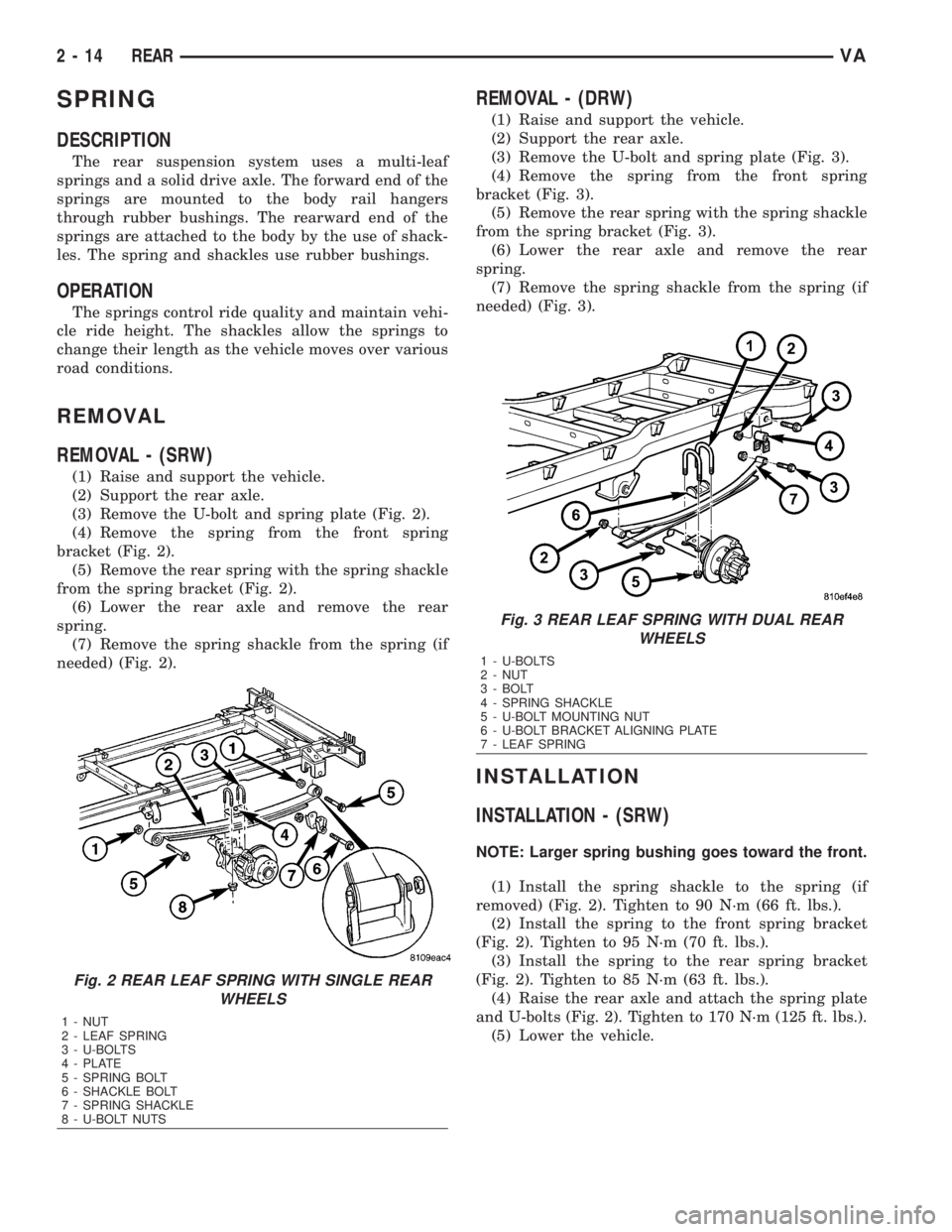
(3) Remove the U-bolt and spring plate (Fig. 2).
(4) Remove the spring from the front spring
bracket (Fig. 2).
(5) Remove the rear spring with the spring shackle
from the spring bracket (Fig. 2).
(6) Lower the rear axle and remove the rear
spring.
(7) Remove the spring shackle from the spring (if
needed) (Fig. 2).
REMOVAL - (DRW)
(1) Raise and support the vehicle.
(2) Support the rear axle.
(3) Remove the U-bolt and spring plate (Fig. 3).
(4) Remove the spring from the front spring
bracket (Fig. 3).
(5) Remove the rear spring with the spring shackle
from the spring bracket (Fig. 3).
(6) Lower the rear axle and remove the rear
spring.
(7) Remove the spring shackle from the spring (if
needed) (Fig. 3).
INSTALLATION
INSTALLATION - (SRW)
NOTE: Larger spring bushing goes toward the front.
(1) Install the spring shackle to the spring (if
removed) (Fig. 2). Tighten to 90 N´m (66 ft. lbs.).
(2) Install the spring to the front spring bracket
(Fig. 2). Tighten to 95 N´m (70 ft. lbs.).
(3) Install the spring to the rear spring bracket
(Fig. 2). Tighten to 85 N´m (63 ft. lbs.).
(4) Raise the rear axle and attach the spring plate
and U-bolts (Fig. 2). Tighten to 170 N´m (125 ft. lbs.).
(5) Lower the vehicle.
Fig. 2 REAR LEAF SPRING WITH SINGLE REAR
WHEELS
1 - NUT
2 - LEAF SPRING
3 - U-BOLTS
4 - PLATE
5 - SPRING BOLT
6 - SHACKLE BOLT
7 - SPRING SHACKLE
8 - U-BOLT NUTS
Fig. 3 REAR LEAF SPRING WITH DUAL REAR
WHEELS
1 - U-BOLTS
2 - NUT
3 - BOLT
4 - SPRING SHACKLE
5 - U-BOLT MOUNTING NUT
6 - U-BOLT BRACKET ALIGNING PLATE
7 - LEAF SPRING
2 - 14 REARVA
Page 749 of 2305
RUNOUT SPECIFICATIONS
Front of Shaft 0.020 in. (0.50 mm)
Center of Shaft 0.025 in. (0.63 mm)
Rear of Shaft 0.020 in. (0.50 mm)
note:
Measure front/rear runout approximately 76 mm (3
in.) from the weld seam at each end of the shaft
tube for tube lengths over 30 inches. For tube
lengths under 30 inches, the maximum allowed
runout is 0.50 mm (0.020 in.) for the full length of
the tube.
STANDARD PROCEDURE
PROPELLER SHAFT ANGLE
This procedure applies the front and rear propeller
shafts.
(1) Place vehicle in netural.
(2) Raise and support vehicle at the axles as level
as possible.
(3) Remove universal joint snap rings if equipped,
so Inclinometer 7663 base sits flat.
(4) Rotate shaft until transmission case output
yoke bearing is facing downward.
NOTE: Always make measurements from front to
rear and from the same side of the vehicle.
(5) Place Inclinometer 7663 on yoke bearing (A)
parallel to the shaft. Center bubble in sight glass and
record measurement.
This measurement will give you the transmis-
sion yoke Output Angle (A).
(6) Rotate propeller shaft 90 degrees and place
inclinometer on yoke bearing parallel to the shaft.
Center bubble in sight glass and record measure-
ment. This measurement can also be taken at the
rear end of the shaft.
This measurement will give you the Propeller
Shaft Angle (C).
(7) Rotate propeller shaft 90 degrees and place
inclinometer on companion flange yoke bearing par-
allel to the shaft. Center bubble in sight glass and
record measurement.
This measurement will give you the Pinion
Flange Input Angle (B).
(8) Subtract smaller figure from larger (C minus
A) to obtain TransmissionOutput Operating
Angle.
(9) Subtract smaller figure from larger (C minus
B) to obtain axleInput Operating Angle.
Refer to rules and example in (Fig. 4) for addi-
tional information.
RULES
²Good cancellation of U-joint operating angles
should be within 1degree.
²Operating angles should be less than 3 degrees.
²At least 1/2 of one degree continuous operating
(propeller shaft) angle.
3 - 4 PROPELLER SHAFTVA
Page 806 of 2305
NOTE: The pressure gauge, connected at the ALB
controller must indicate the outlet pressure which
is assigned on the ALB plate to the rear axle load
determined.
NOTE: If the rear axle load determined is between
two figures indicated on the ALB plate, the outlet
pressure should be determined accordingly.
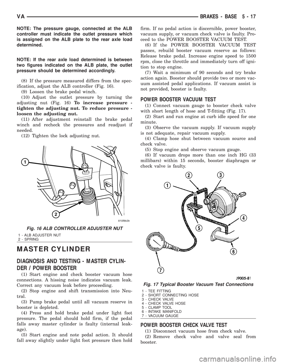
(8) If the pressure measured differs from the spec-
ification, adjust the ALB controller (Fig. 16).
(9) Loosen the brake pedal winch.
(10) Adjust the outlet pressure by turning the
adjusting nut (Fig. 16)To increase pressure -
tighten the adjusting nut. To reduce pressure -
loosen the adjusting nut.
(11) After adjustment reinstall the brake pedal
winch and recheck the pressures and readjust if
needed.
(12) Tighten the lock adjusting nut.
MASTER CYLINDER
DIAGNOSIS AND TESTING - MASTER CYLIN-
DER / POWER BOOSTER
(1) Start engine and check booster vacuum hose
connections. A hissing noise indicates vacuum leak.
Correct any vacuum leak before proceeding.
(2) Stop engine and shift transmission into Neu-
tral.
(3) Pump brake pedal until all vacuum reserve in
booster is depleted.
(4) Press and hold brake pedal under light foot
pressure. The pedal should hold firm, if the pedal
falls away master cylinder is faulty (internal leak-
age).
(5) Start engine and note pedal action. It should
fall away slightly under light foot pressure then holdfirm. If no pedal action is discernible, power booster,
vacuum supply, or vacuum check valve is faulty. Pro-
ceed to the POWER BOOSTER VACUUM TEST.
(6) If the POWER BOOSTER VACUUM TEST
passes, rebuild booster vacuum reserve as follows:
Release brake pedal. Increase engine speed to 1500
rpm, close the throttle and immediately turn off igni-
tion to stop engine.
(7) Wait a minimum of 90 seconds and try brake
action again. Booster should provide two or more vac-
uum assisted pedal applications. If vacuum assist is
not provided, booster is faulty.
POWER BOOSTER VACUUM TEST
(1) Connect vacuum gauge to booster check valve
with short length of hose and T-fitting (Fig. 17).
(2) Start and run engine at curb idle speed for one
minute.
(3) Observe the vacuum supply. If vacuum supply
is not adequate, repair vacuum supply.
(4) Clamp hose shut between vacuum source and
check valve.
(5) Stop engine and observe vacuum gauge.
(6) If vacuum drops more than one inch HG (33
millibars) within 15 seconds, booster diaphragm or
check valve is faulty.
POWER BOOSTER CHECK VALVE TEST
(1) Disconnect vacuum hose from check valve.
(2) Remove check valve and valve seal from
booster.
Fig. 16 ALB CONTROLLER ADJUSTER NUT
1 - ALB ADJUSTER NUT
2 - SPRING
Fig. 17 Typical Booster Vacuum Test Connections
1 - TEE FITTING
2 - SHORT CONNECTING HOSE
3 - CHECK VALVE
4 - CHECK VALVE HOSE
5 - CLAMP TOOL
6 - INTAKE MANIFOLD
7 - VACUUM GAUGE
VABRAKES - BASE 5 - 17
Page 832 of 2305
ACCESSORY DRIVE
TABLE OF CONTENTS
page page
BELT TENSIONERS
DESCRIPTION..........................5
OPERATION............................5
DRIVE BELTS
DIAGNOSIS AND TESTING - ACCESSORY
DRIVE BELT..........................5REMOVAL
REMOVAL............................8
REMOVAL............................8
INSTALLATION
INSTALLATION........................8
INSTALLATION........................8
BELT TENSIONERS
DESCRIPTION
CAUTION: Do not attempt to check belt tension with
a belt tension gauge on vehicles equipped with an
automatic belt tensioner.
Drive belts on all engines are equipped with a
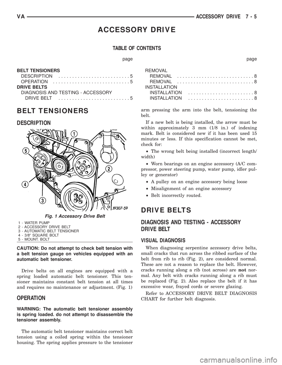
spring loaded automatic belt tensioner. This ten-
sioner maintains constant belt tension at all times
and requires no maintenance or adjustment. (Fig. 1)
OPERATION
WARNING: The automatic belt tensioner assembly
is spring loaded. do not attempt to disassemble the
tensioner assembly.
The automatic belt tensioner maintains correct belt
tension using a coiled spring within the tensioner
housing. The spring applies pressure to the tensionerarm pressing the arm into the belt, tensioning the
belt.
If a new belt is being installed, the arrow must be
within approximately 3 mm (1/8 in.) of indexing
mark. Belt is considered new if it has been used 15
minutes or less. If this specification cannot be met,
check for:
²The wrong belt being installed (incorrect length/
width)
²Worn bearings on an engine accessory (A/C com-
pressor, power steering pump, water pump, idler pul-
ley or generator)
²A pulley on an engine accessory being loose
²Misalignment of an engine accessory
²Belt incorrectly routed.
DRIVE BELTS
DIAGNOSIS AND TESTING - ACCESSORY
DRIVE BELT
VISUAL DIAGNOSIS
When diagnosing serpentine accessory drive belts,
small cracks that run across the ribbed surface of the
belt from rib to rib (Fig. 2), are considered normal.
These are not a reason to replace the belt. However,
cracks running along a rib (not across) arenotnor-
mal. Any belt with cracks running along a rib must
be replaced (Fig. 2). Also replace the belt if it has
excessive wear, frayed cords or severe glazing.
Refer to ACCESSORY DRIVE BELT DIAGNOSIS
CHART for further belt diagnosis.
Fig. 1 Accessory Drive Belt
1 - WATER PUMP
2 - ACCESSORY DRIVE BELT
3 - AUTOMATIC BELT TENSIONER
4 - 3/89SQUARE BOLT
5 - MOUNT. BOLT
VAACCESSORY DRIVE 7 - 5
Page 835 of 2305
REMOVAL
REMOVAL
CAUTION: Do not attempt to check belt tension with
a belt tension gauge on vehicles equipped with an
automatic belt tensioner.
NOTE: The belt routing schematics are published
from the latest information available at the time of
publication. If anything differs between these sche-
matics and the Belt Routing Label, use the sche-
matics on Belt Routing Label.This label is located in
the engine compartment.
(1) Remove A/C compressor drive belt (Refer to 7 -
COOLING/ACCESSORY DRIVE/DRIVE BELTS -
REMOVAL).
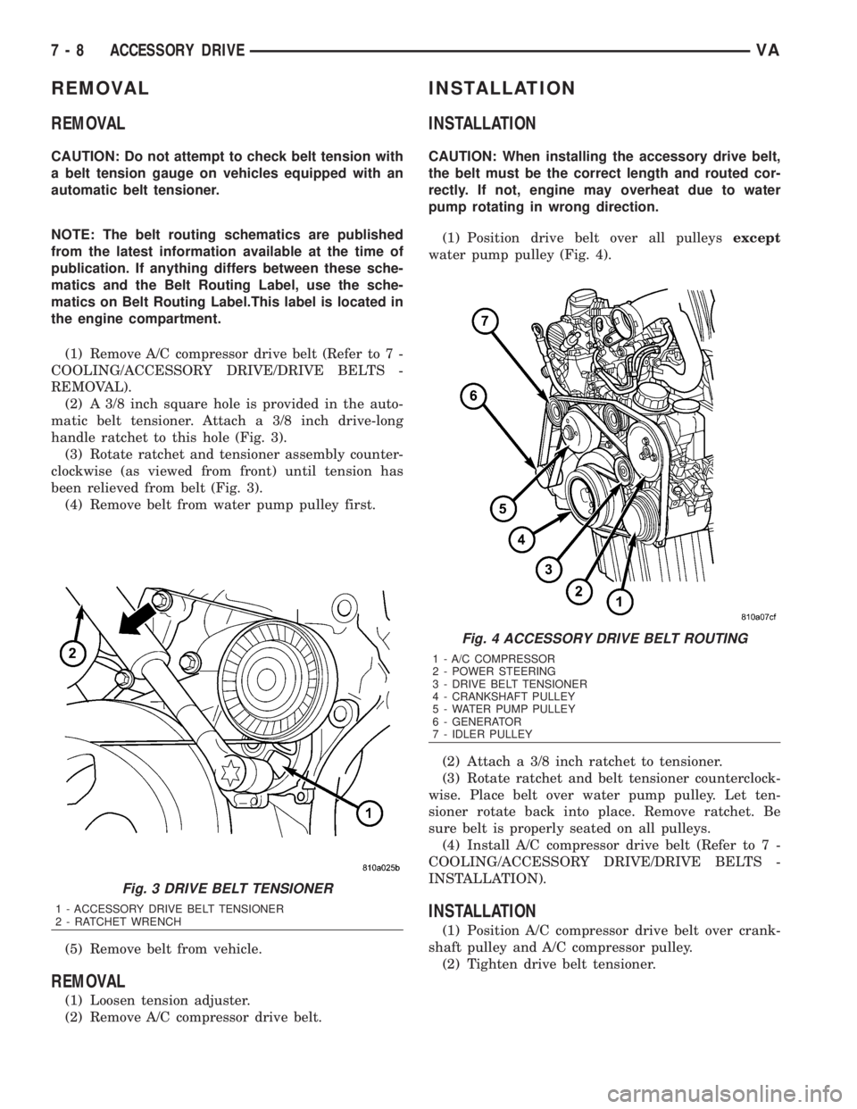
(2) A 3/8 inch square hole is provided in the auto-
matic belt tensioner. Attach a 3/8 inch drive-long
handle ratchet to this hole (Fig. 3).
(3) Rotate ratchet and tensioner assembly counter-
clockwise (as viewed from front) until tension has
been relieved from belt (Fig. 3).
(4) Remove belt from water pump pulley first.
(5) Remove belt from vehicle.
REMOVAL
(1) Loosen tension adjuster.
(2) Remove A/C compressor drive belt.
INSTALLATION
INSTALLATION
CAUTION: When installing the accessory drive belt,
the belt must be the correct length and routed cor-
rectly. If not, engine may overheat due to water
pump rotating in wrong direction.
(1) Position drive belt over all pulleysexcept
water pump pulley (Fig. 4).
(2) Attach a 3/8 inch ratchet to tensioner.
(3) Rotate ratchet and belt tensioner counterclock-
wise. Place belt over water pump pulley. Let ten-
sioner rotate back into place. Remove ratchet. Be
sure belt is properly seated on all pulleys.
(4) Install A/C compressor drive belt (Refer to 7 -
COOLING/ACCESSORY DRIVE/DRIVE BELTS -
INSTALLATION).
INSTALLATION
(1) Position A/C compressor drive belt over crank-
shaft pulley and A/C compressor pulley.
(2) Tighten drive belt tensioner.
Fig. 3 DRIVE BELT TENSIONER
1 - ACCESSORY DRIVE BELT TENSIONER
2 - RATCHET WRENCH
Fig. 4 ACCESSORY DRIVE BELT ROUTING
1 - A/C COMPRESSOR
2 - POWER STEERING
3 - DRIVE BELT TENSIONER
4 - CRANKSHAFT PULLEY
5 - WATER PUMP PULLEY
6 - GENERATOR
7 - IDLER PULLEY
7 - 8 ACCESSORY DRIVEVA
Page 1046 of 2305
both the wiper and washer systems. (Refer to 8 -
ELECTRICAL/LAMPS/LIGHTING - EXTERIOR/
MULTI-FUNCTION SWITCH - DESCRIPTION)
²Rain Sensor- Vehicles equipped with an
optional automatic wiper feature have an electronic
rain sensor concealed within the base of the rear
view mirror unit on the inside of the laminated wind-
shield glass.
²Rain Sensor Control Module- Vehicles
equipped with an optional automatic wiper feature
have an electronic rain sensor control module located
under the lower instrument panel above the acceler-
ator pedal in the passenger compartment of the vehi-
cle.
²Washer Fluid Level Switch- The optional
washer fluid level switch is integral to a unique ver-
sion of the washer pump/motor unit, which is located
in a dedicated hole on the top of the sump area near
the back of the windshield washer reservoir on the
right front fender wheel house in the engine com-
partment.
²Washer Nozzle- A single washer nozzle with
three separate orifices is secured with integral snap
features to each wiper arm. The hoses for the washer
nozzles are concealed beneath a molded plastic guide
on the underside of each wiper arm and routed to the
engine compartment through unique molded plastic
elbow fittings located near each wiper pivot at the
base of the windshield.
²Washer Pump/Motor- Two different washer
pump/motor units are available for this model. One
version has an integral washer fluid level switch that
provides a hard wired input to the instrument cluster
for control of the optional washer fluid indicator. The
washer pump/motor unit is located in a dedicated
hole on the top of the sump area near the back of the
windshield washer reservoir on the right front fender
wheel house in the engine compartment.
²Washer Reservoir- The washer reservoir is
located on the right front fender wheel house in the
engine compartment. The washer reservoir filler is
accessed from the right front corner of the engine
compartment.
²Wiper Arm- The two unequal length wiper
arms are secured to the two wiper pivots, which
extend through the cowl panel near the base of the
windshield. The longer arm is installed on the left
(driver) side of the windshield.
²Wiper Blade- The two unequal length wiper
blades are secured to the two wiper arms, and are
parked on the glass near the bottom of the wind-
shield when the wiper system is not in operation.
The longer blade is installed on the left (driver) side
of the windshield.
²Wiper Linkage- The wiper pivots are the only
visible components of the wiper linkage. The remain-
der of the linkage is concealed within the engine
compartment just behind the hood opening. Thewiper linkage module includes the two wiper drive
links, the wiper motor crank arm, the two wiper piv-
ots, and the linkage and motor mounting bracket.
²Wiper Motor- The wiper motor is secured to
the wiper linkage module bracket on the underside of
the cowl panel within the engine compartment. The
wiper motor output shaft and crank arm extend
through a clearance hole in the mounting bracket,
where they are connected to a crank arm that drives
the wiper linkage.
²Wiper Relay- The wiper relay is located in a
dedicated receptacle on the lower left surface of the
fuse block underneath the steering column behind
the fuse access panel and the steering column open-
ing panel. The wiper relay is a passive component on
vehicles equipped with the optional automatic wiper
system.
²Wiper, Turn Signals, Engine Start Control
Module- The wiper, turn signals and engine start
control module is integral to the fuse block located
underneath the steering column. The fuse block is
concealed behind the fuse access panel and the steer-
ing column opening panel, where it is secured with
screws to the steering column. The wiper system
functions of this module are passive on vehicles
equipped with the optional automatic wiper system.
Hard wired circuitry connects the wiper and
washer system components to the electrical system of
the vehicle. These hard wired circuits are integral to
several wire harnesses, which are routed throughout
the vehicle and retained by many different methods.
These circuits may be connected to each other, to the
vehicle electrical system and to the wiper and washer
system components through the use of a combination
of soldered splices, splice block connectors, and many
different types of wire harness terminal connectors
and insulators. Refer to the appropriate wiring infor-
mation. The wiring information includes wiring dia-
grams, proper wire and connector repair procedures,
further details on wire harness routing and reten-
tion, as well as pin-out and location views for the
various wire harness connectors, splices and grounds.
OPERATION
The wiper and washer system is designed to pro-
vide the vehicle operator with a convenient, safe, and
reliable means of maintaining visibility through the
windshield glass. The various components of this sys-
tem are designed to convert electrical energy pro-
duced by the vehicle electrical system into the
mechanical action of the wiper blades to wipe the
outside surface of the glass, as well as into the
hydraulic action of the washer system to apply
washer fluid stored in an on-board reservoir to the
area of the glass to be wiped. When combined, these
components provide the means to effectively main-
tain clear visibility for the vehicle operator by remov-
ing excess accumulations of rain, snow, bugs, mud, or
VAWIPERS/WASHERS 8R - 3