2006 MERCEDES-BENZ SPRINTER bolt pattern
[x] Cancel search: bolt patternPage 789 of 2305
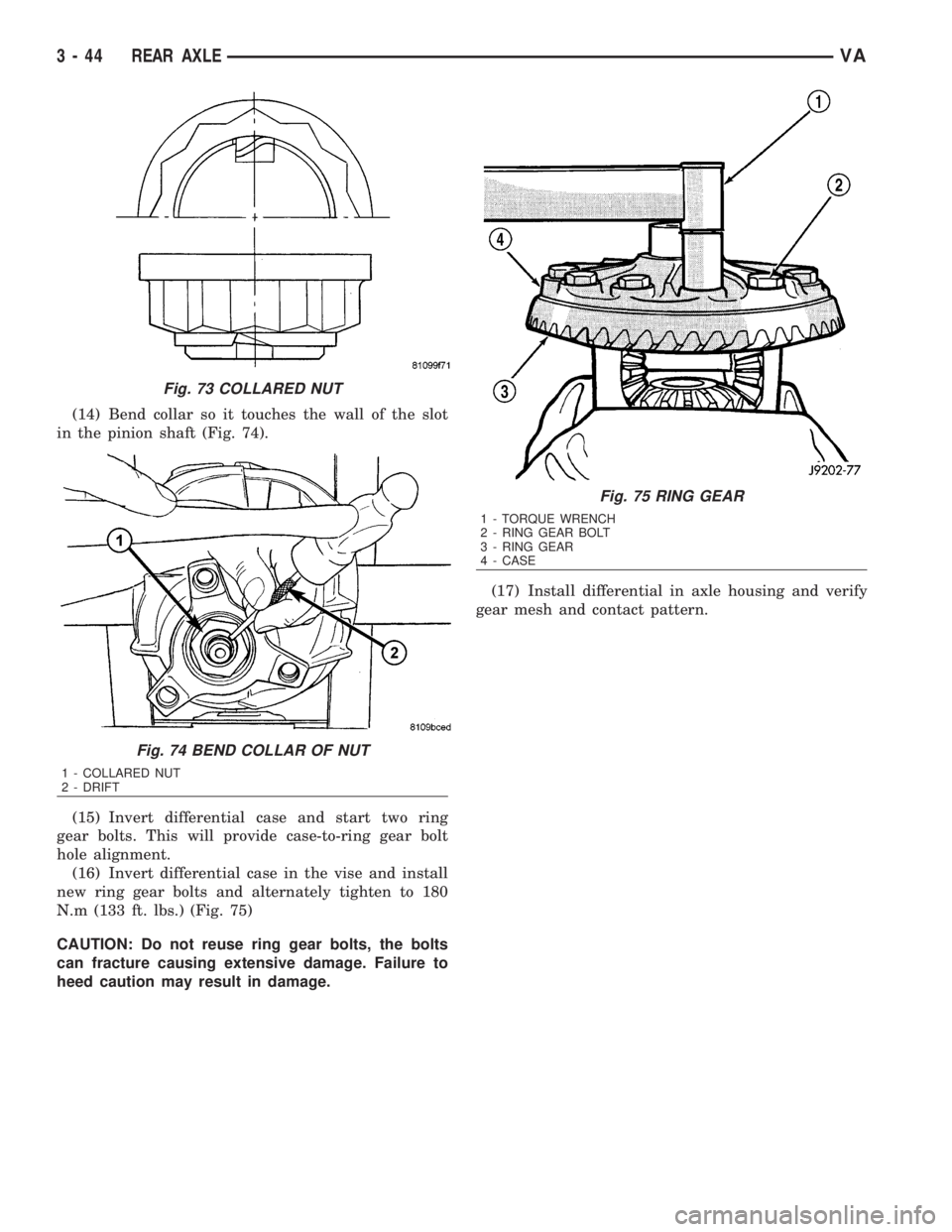
(14) Bend collar so it touches the wall of the slot
in the pinion shaft (Fig. 74).
(15) Invert differential case and start two ring
gear bolts. This will provide case-to-ring gear bolt
hole alignment.
(16) Invert differential case in the vise and install
new ring gear bolts and alternately tighten to 180
N.m (133 ft. lbs.) (Fig. 75)
CAUTION: Do not reuse ring gear bolts, the bolts
can fracture causing extensive damage. Failure to
heed caution may result in damage.(17) Install differential in axle housing and verify
gear mesh and contact pattern.
Fig. 73 COLLARED NUT
Fig. 74 BEND COLLAR OF NUT
1 - COLLARED NUT
2 - DRIFT
Fig. 75 RING GEAR
1 - TORQUE WRENCH
2 - RING GEAR BOLT
3 - RING GEAR
4 - CASE
3 - 44 REAR AXLEVA
Page 900 of 2305
INSTALLATION
(1) Raise and support vehicle.
(2) Position starter motor to transmission housing.
(3) Install 2 mounting bolts. Refer to Torque Spec-
ifications.
(4) Lower vehicle.
(5) Connect battery cable and solenoid wiring to
solenoid (2 nuts). Refer to Torque Specifications.
(6) Position wiring harness trough and install
retaining bolt.
(7) Install new nylon tie-wraps to wiring trough.
(8) Connect negative battery cable.
STARTER MOTOR RELAY
DESCRIPTION
The starter relay is an electromechanical device
that switches battery current to the pull-in coil of the
starter solenoid when ignition switch is turned to
Start position. The starter relay is located in the
Fuse/Relay Block. The Fuse/Relay Block is located
under, and to the left side of the drivers seat. See
Fuse/Relay Block cover for relay identification and
location.
The starter relay is an International Standards
Organization (ISO) relay. Relays conforming to ISO
specifications have common physical dimensions, cur-rent capacities, terminal patterns, and terminal func-
tions.
The starter relay cannot be repaired or adjusted
and, if faulty or damaged, it must be replaced.
REMOVAL
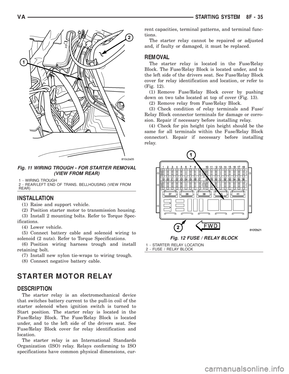
The starter relay is located in the Fuse/Relay
Block. The Fuse/Relay Block is located under, and to
the left side of the drivers seat. See Fuse/Relay Block
cover for relay identification and location, or refer to
(Fig. 12).
(1) Remove Fuse/Relay Block cover by pushing
down on two tabs located at top of cover (Fig. 13).
(2) Remove relay from Fuse/Relay Block.
(3) Check condition of relay terminals and Fuse/
Relay Block connector terminals for damage or corro-
sion. Repair if necessary before installing relay.
(4) Check for pin height (pin height should be the
same for all terminals within the Fuse/Relay Block
connector). Repair if necessary before installing
relay.
Fig. 11 WIRING TROUGH - FOR STARTER REMOVAL
(VIEW FROM REAR)
1 - WIRING TROUGH
2 - REAR/LEFT END OF TRANS. BELLHOUSING (VIEW FROM
REAR)
Fig. 12 FUSE / RELAY BLOCK
1 - STARTER RELAY LOCATION
2 - FUSE / RELAY BLOCK
VASTARTING SYSTEM 8F - 35
Page 1643 of 2305
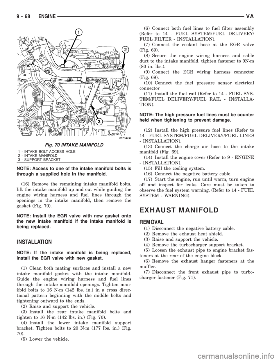
NOTE: Access to one of the intake manifold bolts is
through a supplied hole in the manifold.
(16) Remove the remaining intake manifold bolts,
lift the intake manifold up and out while guiding the
engine wiring harness and fuel lines through the
openings in the intake manifold, then remove the
gasket (Fig. 70).
NOTE: Install the EGR valve with new gasket onto
the new intake manifold if the intake manifold is
being replaced.
INSTALLATION
NOTE: If the intake manifold is being replaced,
install the EGR valve with new gasket.
(1) Clean both mating surfaces and install a new
intake manifold gasket with the intake manifold.
Guide the engine wiring harness and fuel lines
through the intake manifold openings. Tighten man-
ifold bolts to 16 N´m (142 lbs. in.) in a cross direc-
tional pattern beginning with the middle bolts and
tightening outward to the ends.
(2) Raise and support the vehicle.
(3) Install the rear intake manifold bolts and
tighten to 16 N´m (142 lbs. in.) (Fig. 70).
(4) Install the lower intake manifold support
bracket. Tighten bolts to 20 N´m (177 lbs. in.) (Fig.
70).
(5) Lower the vehicle.(6) Connect both fuel lines to fuel filter assembly
(Refer to 14 - FUEL SYSTEM/FUEL DELIVERY/
FUEL FILTER - INSTALLATION).
(7) Connect the coolant hose at the EGR valve
(Fig. 69).
(8) Secure the engine wiring harness and cable
duct to the intake manifold. tighten fastener to 9N´m
(80 in. lbs.).
(9) Connect the EGR wiring harness connector
(Fig. 69).
(10) Connect the fuel pressure sensor electrical
connector
(11) Install the fuel rail (Refer to 14 - FUEL SYS-
TEM/FUEL DELIVERY/FUEL RAIL - INSTALLA-
TION).
NOTE: The high pressure fuel lines must be counter
held when tightening to prevent damage.
(12) Install the high pressure fuel lines (Refer to
14 - FUEL SYSTEM/FUEL DELIVERY/FUEL LINES
- INSTALLATION).
(13) Connect the charge air hose to the intake
manifold (Fig. 69).
(14) Install the engine cover (Refer to 9 - ENGINE
- INSTALLATION).
(15) Fill the cooling system.
(16) Connect the negative battery cable.
(17) Start the engine, run until warm, turn engine
off and inspect for leaks. Care must be taken to
observe the fuel system warning. (Refer to 14 - FUEL
SYSTEM - WARNING).
EXHAUST MANIFOLD
REMOVAL
(1) Disconnect the negative battery cable.
(2) Remove the exhaust heat shield.
(3) Raise and support the vehicle.
(4) Remove the turbocharger support bracket.
(5) Loosen the exhaust pipe to engine bracket fas-
teners at the rear of the engine block.
(6) Remove the exhaust hanger fasteners at the
muffler.
(7) Disconnect the front exhaust pipe to turbo-
charger fastener (Fig. 71).
Fig. 70 INTAKE MANIFOLD
1 - INTAKE BOLT ACCESS HOLE
2 - INTAKE MANIFOLD
3 - SUPPORT BRACKET
9 - 68 ENGINEVA
Page 1958 of 2305
(7) Install mirror. (Refer to 23 - BODY/EXTERI-
OR/SIDE VIEW MIRROR - INSTALLATION)
(8) Adjust door if required. (Refer to 23 - BODY/
DOOR - FRONT/DOOR - ADJUSTMENTS)
(9) Connect battery negative cable.
ADJUSTMENTS
ADJUSTMENT
NOTE: Door adjustment measurements should be
taken from stationary or welded body panels like
the roof, rocker or quarter panels.
²During adjustment procedures, it is recom-
mended that all the hinge fasteners be loosened
except for the upper most fasteners. Adjustments
can be made using the upper bolts to hold the door
with final torque of the fasteners occurring after
correct door positioning is achieved.
²A suitable body sealant should be used when
removing or moving the hinges.
(1) Check door alignment. (Refer to 23 - BODY/
BODY STRUCTURE/GAP AND FLUSH - SPECIFI-
CATIONS)
(2) If adjustment is required, remove latch striker.
(Refer to 23 - BODY/DOOR - FRONT/LATCH
STRIKER - REMOVAL)
(3) Remove side view mirror. (Refer to 23 - BODY/
EXTERIOR/SIDE VIEW MIRROR - REMOVAL)
(4) Loosen hinge bolts and adjust door gap and
align ridge pattern as necessary.
(5) Tighten hinge bolts to 25 N´m (18 ft. lbs.).
(6) Install latch striker and adjust flush measure-
ment as necessary. (Refer to 23 - BODY/DOOR -
FRONT/LATCH STRIKER - INSTALLATION)
(7) Install side view mirror. (Refer to 23 - BODY/
EXTERIOR/SIDE VIEW MIRROR - INSTALLA-
TION)
DOOR GLASS
REMOVAL
(1) Remove the regulator. (Refer to 23 - BODY/
DOOR - FRONT/WINDOW REGULATOR - POWER
or MANUAL - REMOVAL)
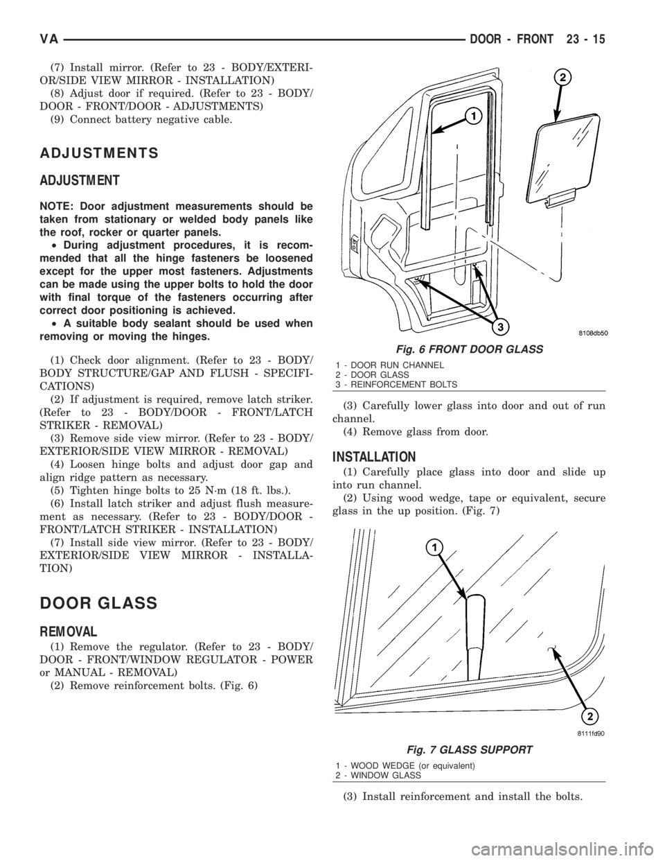
(2) Remove reinforcement bolts. (Fig. 6)(3) Carefully lower glass into door and out of run
channel.
(4) Remove glass from door.
INSTALLATION
(1) Carefully place glass into door and slide up
into run channel.
(2) Using wood wedge, tape or equivalent, secure
glass in the up position. (Fig. 7)
(3) Install reinforcement and install the bolts.
Fig. 6 FRONT DOOR GLASS
1 - DOOR RUN CHANNEL
2 - DOOR GLASS
3 - REINFORCEMENT BOLTS
Fig. 7 GLASS SUPPORT
1 - WOOD WEDGE (or equivalent)
2 - WINDOW GLASS
VADOOR - FRONT 23 - 15
Page 1987 of 2305
(14) Install the door. (Refer to 23 - BODY/DOORS
- SLIDING/SLIDING DOOR - INSTALLATION)
INSTALLATION
(1) Install the door by inserting the center and
upper rollers into the tracks and sliding the door for-
ward to the front of each track.
(2) Connect the lower roller arm and install the
screws.
(3) Tighten the screws to 25 N´m (18 ft. lbs.).
(4) Install door stop and screws.
(5) Tighten the screws to 10 N´m (89 in. lbs.).
(6) Install the center track end piece and install
the screw.
(7) Tighten the screw to 10 N´m (89 in. lbs.).
(8) Check and adjust door if necessary. (Refer to 23
- BODY/DOORS - SLIDING/SLIDING DOOR -
ADJUSTMENTS)
(9) Connect battery negative cable.
ADJUSTMENTS
ADJUSTMENT
NOTE: Door adjustment measurements should be
taken from stationary or welded body panels like
the roof, rocker or quarter panels.
A suitable body sealant should be used when
removing or moving the hinges.
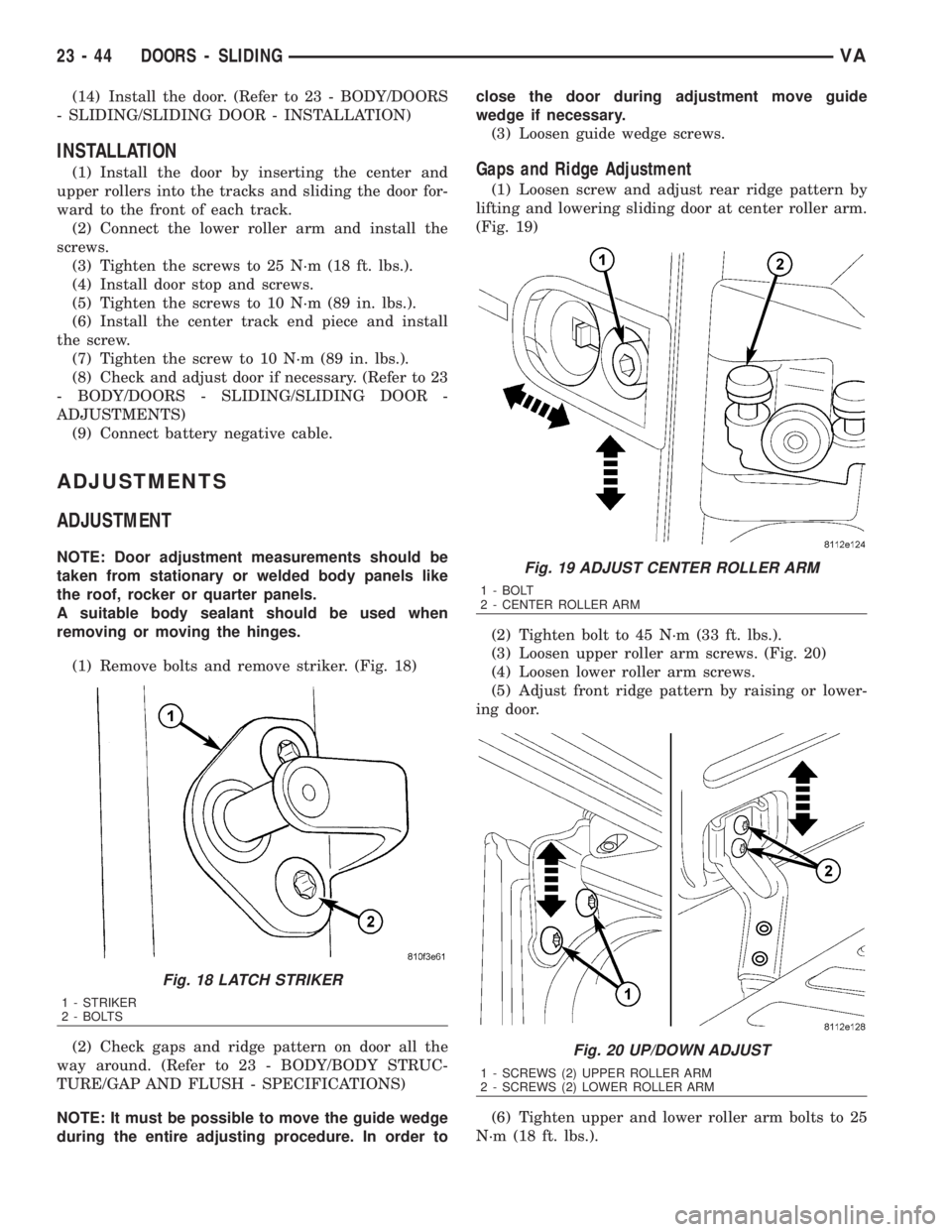
(1) Remove bolts and remove striker. (Fig. 18)
(2) Check gaps and ridge pattern on door all the
way around. (Refer to 23 - BODY/BODY STRUC-
TURE/GAP AND FLUSH - SPECIFICATIONS)
NOTE: It must be possible to move the guide wedge
during the entire adjusting procedure. In order toclose the door during adjustment move guide
wedge if necessary.
(3) Loosen guide wedge screws.
Gaps and Ridge Adjustment
(1) Loosen screw and adjust rear ridge pattern by
lifting and lowering sliding door at center roller arm.
(Fig. 19)
(2) Tighten bolt to 45 N´m (33 ft. lbs.).
(3) Loosen upper roller arm screws. (Fig. 20)
(4) Loosen lower roller arm screws.
(5) Adjust front ridge pattern by raising or lower-
ing door.
(6) Tighten upper and lower roller arm bolts to 25
N´m (18 ft. lbs.).
Fig. 18 LATCH STRIKER
1 - STRIKER
2 - BOLTS
Fig. 19 ADJUST CENTER ROLLER ARM
1 - BOLT
2 - CENTER ROLLER ARM
Fig. 20 UP/DOWN ADJUST
1 - SCREWS (2) UPPER ROLLER ARM
2 - SCREWS (2) LOWER ROLLER ARM
23 - 44 DOORS - SLIDINGVA
Page 1988 of 2305
(7) Loosen center roller bolt and adjust the front
and rear gaps.
(8) Check rear ridge pattern alignment and
tighten bolt to 45 N´m (33 ft. lbs.).
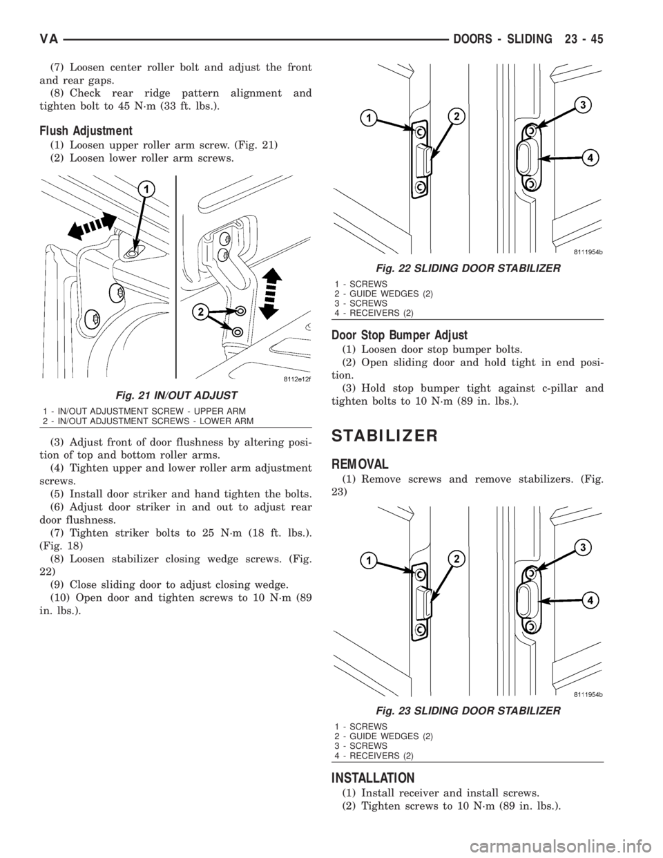
Flush Adjustment
(1) Loosen upper roller arm screw. (Fig. 21)
(2) Loosen lower roller arm screws.
(3) Adjust front of door flushness by altering posi-
tion of top and bottom roller arms.
(4) Tighten upper and lower roller arm adjustment
screws.
(5) Install door striker and hand tighten the bolts.
(6) Adjust door striker in and out to adjust rear
door flushness.
(7) Tighten striker bolts to 25 N´m (18 ft. lbs.).
(Fig. 18)
(8) Loosen stabilizer closing wedge screws. (Fig.
22)
(9) Close sliding door to adjust closing wedge.
(10) Open door and tighten screws to 10 N´m (89
in. lbs.).
Door Stop Bumper Adjust
(1) Loosen door stop bumper bolts.
(2) Open sliding door and hold tight in end posi-
tion.
(3) Hold stop bumper tight against c-pillar and
tighten bolts to 10 N´m (89 in. lbs.).
STABILIZER
REMOVAL
(1) Remove screws and remove stabilizers. (Fig.
23)
INSTALLATION
(1) Install receiver and install screws.
(2) Tighten screws to 10 N´m (89 in. lbs.).
Fig. 21 IN/OUT ADJUST
1 - IN/OUT ADJUSTMENT SCREW - UPPER ARM
2 - IN/OUT ADJUSTMENT SCREWS - LOWER ARM
Fig. 22 SLIDING DOOR STABILIZER
1 - SCREWS
2 - GUIDE WEDGES (2)
3 - SCREWS
4 - RECEIVERS (2)
Fig. 23 SLIDING DOOR STABILIZER
1 - SCREWS
2 - GUIDE WEDGES (2)
3 - SCREWS
4 - RECEIVERS (2)
VADOORS - SLIDING 23 - 45