2006 MERCEDES-BENZ SPRINTER cooling
[x] Cancel search: coolingPage 106 of 2305

Symptom List:
HEATER IN LOCKOUT MODE
HEATER OVERHEATED
SUCCESSIVE OVERHEATING
Test Note: All symptoms listed above are diagnosed using the same tests.
The title for the tests will be HEATER IN LOCKOUT MODE.
When Monitored and Set Condition:
HEATER IN LOCKOUT MODE
When Monitored: During heater activation and operation.
Set Condition: This DTC will set if multiple attempts to start the heater have failed or if
successive overheating occurs.
HEATER OVERHEATED
When Monitored: After heater activation, when the system is in a steady state of
operation.
Set Condition: This DTC will set if the Temperature Sensor's resistance or Overheating
Sensor's resistance is not within the expected parameters (coolant temperature in the
heater module exceeds 105ÉC [221ÉF]).
SUCCESSIVE OVERHEATING
When Monitored: After heater activation, when the system is in a steady state of
operation.
Set Condition: This DTC will set if successive overheating occurs.
POSSIBLE CAUSES
CABIN HEATER ASSEMBLY OR HEATER BOOSTER ASSEMBLY
HEATER'S COOLANT HOSES RESTRICTED/LEAKING/DAMAGED
ENGINE'S COOLING SYSTEM FAULT
CABIN HEATER OR HEATER BOOSTER CONTROL UNIT
HEATER OVERHEATED/SUCCESSIVE OVERHEATING CLEARED, ADDITIONAL DTC(S)
PRESENT
93
CABIN HEATER
Page 107 of 2305

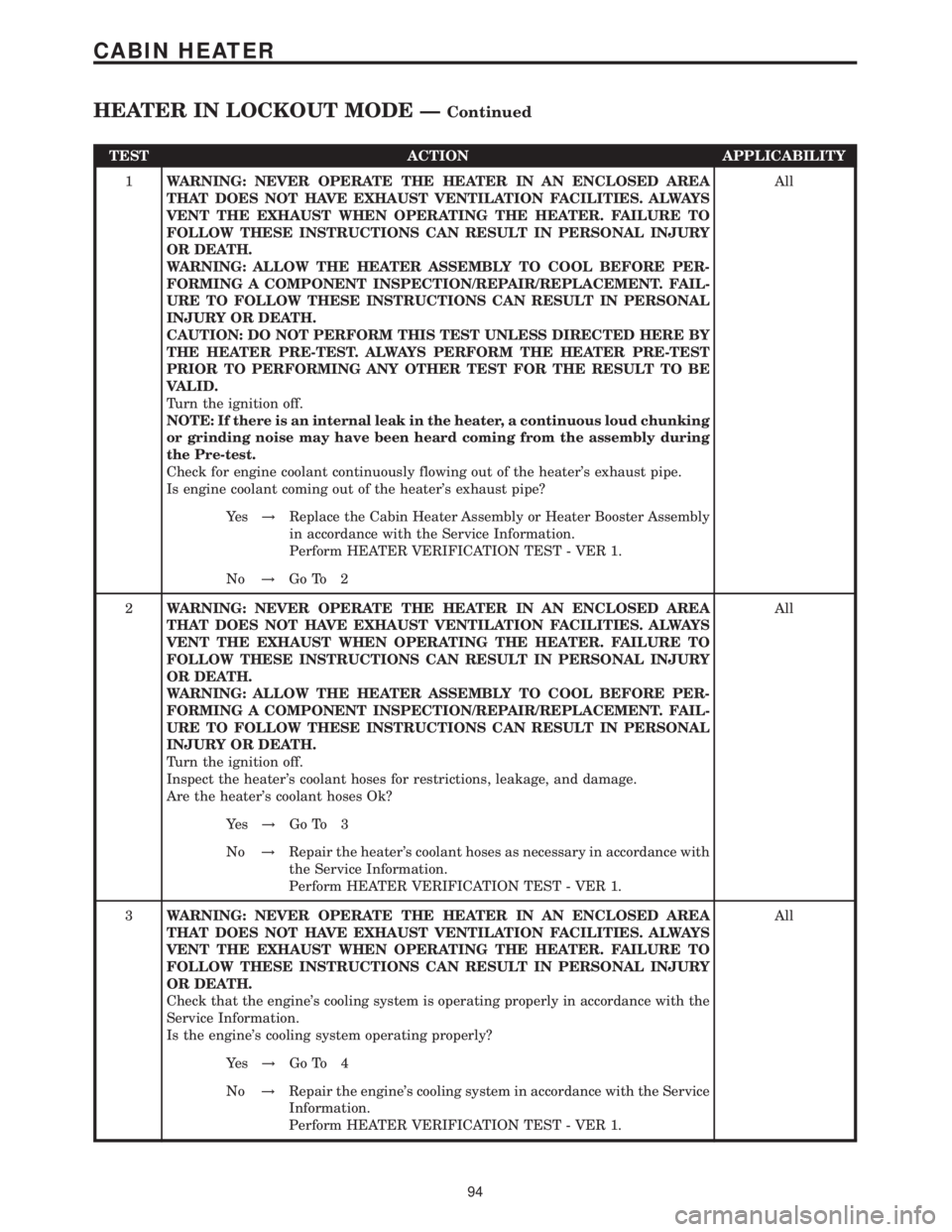
TEST ACTION APPLICABILITY
1WARNING: NEVER OPERATE THE HEATER IN AN ENCLOSED AREA
THAT DOES NOT HAVE EXHAUST VENTILATION FACILITIES. ALWAYS
VENT THE EXHAUST WHEN OPERATING THE HEATER. FAILURE TO
FOLLOW THESE INSTRUCTIONS CAN RESULT IN PERSONAL INJURY
OR DEATH.
WARNING: ALLOW THE HEATER ASSEMBLY TO COOL BEFORE PER-
FORMING A COMPONENT INSPECTION/REPAIR/REPLACEMENT. FAIL-
URE TO FOLLOW THESE INSTRUCTIONS CAN RESULT IN PERSONAL
INJURY OR DEATH.
CAUTION: DO NOT PERFORM THIS TEST UNLESS DIRECTED HERE BY
THE HEATER PRE-TEST. ALWAYS PERFORM THE HEATER PRE-TEST
PRIOR TO PERFORMING ANY OTHER TEST FOR THE RESULT TO BE
VALID.
Turn the ignition off.
NOTE: If there is an internal leak in the heater, a continuous loud chunking
or grinding noise may have been heard coming from the assembly during
the Pre-test.
Check for engine coolant continuously flowing out of the heater's exhaust pipe.
Is engine coolant coming out of the heater's exhaust pipe?All
Ye s!Replace the Cabin Heater Assembly or Heater Booster Assembly
in accordance with the Service Information.
Perform HEATER VERIFICATION TEST - VER 1.
No!Go To 2
2WARNING: NEVER OPERATE THE HEATER IN AN ENCLOSED AREA
THAT DOES NOT HAVE EXHAUST VENTILATION FACILITIES. ALWAYS
VENT THE EXHAUST WHEN OPERATING THE HEATER. FAILURE TO
FOLLOW THESE INSTRUCTIONS CAN RESULT IN PERSONAL INJURY
OR DEATH.
WARNING: ALLOW THE HEATER ASSEMBLY TO COOL BEFORE PER-
FORMING A COMPONENT INSPECTION/REPAIR/REPLACEMENT. FAIL-
URE TO FOLLOW THESE INSTRUCTIONS CAN RESULT IN PERSONAL
INJURY OR DEATH.
Turn the ignition off.
Inspect the heater's coolant hoses for restrictions, leakage, and damage.
Are the heater's coolant hoses Ok?All
Ye s!Go To 3
No!Repair the heater's coolant hoses as necessary in accordance with
the Service Information.
Perform HEATER VERIFICATION TEST - VER 1.
3WARNING: NEVER OPERATE THE HEATER IN AN ENCLOSED AREA
THAT DOES NOT HAVE EXHAUST VENTILATION FACILITIES. ALWAYS
VENT THE EXHAUST WHEN OPERATING THE HEATER. FAILURE TO
FOLLOW THESE INSTRUCTIONS CAN RESULT IN PERSONAL INJURY
OR DEATH.
Check that the engine's cooling system is operating properly in accordance with the
Service Information.
Is the engine's cooling system operating properly?All
Ye s!Go To 4
No!Repair the engine's cooling system in accordance with the Service
Information.
Perform HEATER VERIFICATION TEST - VER 1.
94
CABIN HEATER
HEATER IN LOCKOUT MODE ÐContinued
Page 108 of 2305

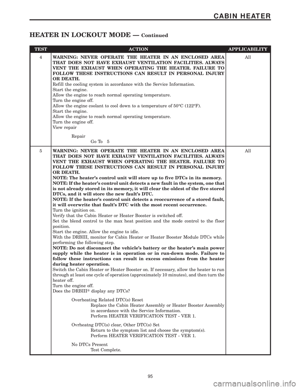
TEST ACTION APPLICABILITY
4WARNING: NEVER OPERATE THE HEATER IN AN ENCLOSED AREA
THAT DOES NOT HAVE EXHAUST VENTILATION FACILITIES. ALWAYS
VENT THE EXHAUST WHEN OPERATING THE HEATER. FAILURE TO
FOLLOW THESE INSTRUCTIONS CAN RESULT IN PERSONAL INJURY
OR DEATH.
Refill the cooling system in accordance with the Service Information.
Start the engine.
Allow the engine to reach normal operating temperature.
Turn the engine off.
Allow the engine coolant to cool down to a temperature of 50ÉC (122ÉF).
Start the engine.
Allow the engine to reach normal operating temperature.
Turn the engine off.
View repairAll
Repair
Go To 5
5WARNING: NEVER OPERATE THE HEATER IN AN ENCLOSED AREA
THAT DOES NOT HAVE EXHAUST VENTILATION FACILITIES. ALWAYS
VENT THE EXHAUST WHEN OPERATING THE HEATER. FAILURE TO
FOLLOW THESE INSTRUCTIONS CAN RESULT IN PERSONAL INJURY
OR DEATH.
NOTE: The heater's control unit will store up to five DTCs in its memory.
NOTE: If the heater's control unit detects a new fault in the system, one that
is not already stored in its memory, it will clear the oldest of the five stored
DTCs, and it will store the new fault's DTC.
NOTE: If the heater's control unit detects a reoccurrence of a stored fault,
it will overwrite that fault's DTC with the most recent occurrence.
Turn the ignition on.
Verify that the Cabin Heater or Heater Booster is switched off.
Set the blend control to the max heat position and the mode control to the floor
position.
Start the engine. Allow the engine to idle.
With the DRBIII, monitor for Cabin Heater or Heater Booster Module DTCs while
performing the following step.
NOTE: Do not disconnect the vehicle's battery or the heater's main power
supply while the heater is in operation or in run-down mode. Failure to
follow these instructions can result in excess emissions from the heater
during heater operation.
Switch the Cabin Heater or Heater Booster on. If necessary, allow the heater to run
through at least one cycle of operation (approximately 10 minutes), and then turn the
heater off.
Turn the engine off.
Does the DRBIIItdisplay any DTCs?All
Overheating Related DTC(s) Reset
Replace the Cabin Heater Assembly or Heater Booster Assembly
in accordance with the Service Information.
Perform HEATER VERIFICATION TEST - VER 1.
Ovrheatng DTC(s) clear, Other DTC(s) Set
Return to the symptom list and choose the symptom(s).
Perform HEATER VERIFICATION TEST - VER 1.
No DTCs Present
Test Complete.
95
CABIN HEATER
HEATER IN LOCKOUT MODE ÐContinued
Page 259 of 2305

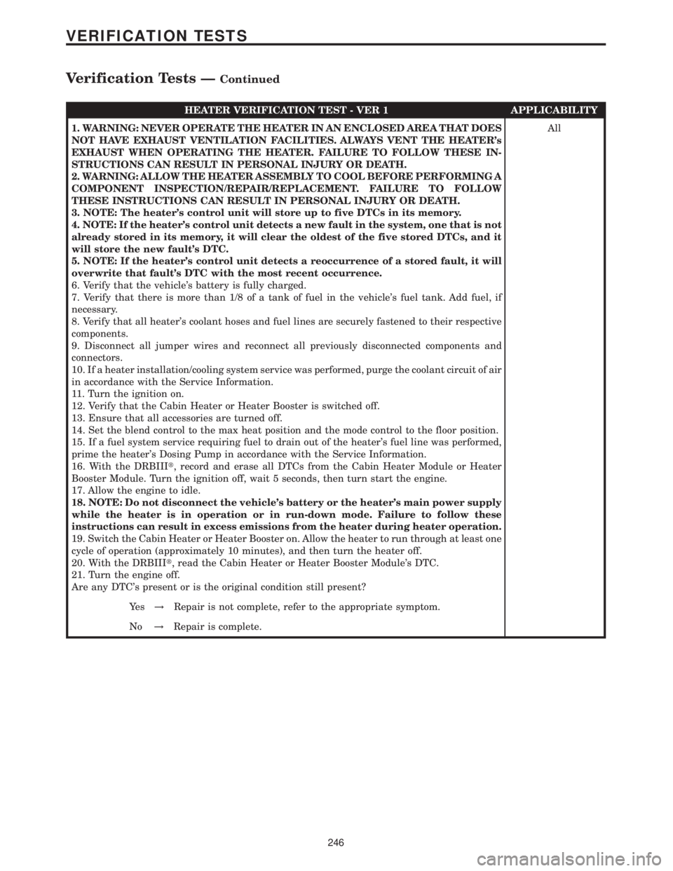
HEATER VERIFICATION TEST - VER 1 APPLICABILITY
1. WARNING: NEVER OPERATE THE HEATER IN AN ENCLOSED AREA THAT DOES
NOT HAVE EXHAUST VENTILATION FACILITIES. ALWAYS VENT THE HEATER's
EXHAUST WHEN OPERATING THE HEATER. FAILURE TO FOLLOW THESE IN-
STRUCTIONS CAN RESULT IN PERSONAL INJURY OR DEATH.
2. WARNING: ALLOW THE HEATER ASSEMBLY TO COOL BEFORE PERFORMING A
COMPONENT INSPECTION/REPAIR/REPLACEMENT. FAILURE TO FOLLOW
THESE INSTRUCTIONS CAN RESULT IN PERSONAL INJURY OR DEATH.
3. NOTE: The heater's control unit will store up to five DTCs in its memory.
4. NOTE: If the heater's control unit detects a new fault in the system, one that is not
already stored in its memory, it will clear the oldest of the five stored DTCs, and it
will store the new fault's DTC.
5. NOTE: If the heater's control unit detects a reoccurrence of a stored fault, it will
overwrite that fault's DTC with the most recent occurrence.
6. Verify that the vehicle's battery is fully charged.
7. Verify that there is more than 1/8 of a tank of fuel in the vehicle's fuel tank. Add fuel, if
necessary.
8. Verify that all heater's coolant hoses and fuel lines are securely fastened to their respective
components.
9. Disconnect all jumper wires and reconnect all previously disconnected components and
connectors.
10. If a heater installation/cooling system service was performed, purge the coolant circuit of air
in accordance with the Service Information.
11. Turn the ignition on.
12. Verify that the Cabin Heater or Heater Booster is switched off.
13. Ensure that all accessories are turned off.
14. Set the blend control to the max heat position and the mode control to the floor position.
15. If a fuel system service requiring fuel to drain out of the heater's fuel line was performed,
prime the heater's Dosing Pump in accordance with the Service Information.
16. With the DRBIIIt, record and erase all DTCs from the Cabin Heater Module or Heater
Booster Module. Turn the ignition off, wait 5 seconds, then turn start the engine.
17. Allow the engine to idle.
18. NOTE: Do not disconnect the vehicle's battery or the heater's main power supply
while the heater is in operation or in run-down mode. Failure to follow these
instructions can result in excess emissions from the heater during heater operation.
19. Switch the Cabin Heater or Heater Booster on. Allow the heater to run through at least one
cycle of operation (approximately 10 minutes), and then turn the heater off.
20. With the DRBIIIt, read the Cabin Heater or Heater Booster Module's DTC.
21. Turn the engine off.
Are any DTC's present or is the original condition still present?All
Ye s!Repair is not complete, refer to the appropriate symptom.
No!Repair is complete.
246
VERIFICATION TESTS
Verification Tests ÐContinued
Page 425 of 2305

3.2.2 ECM OPERATING MODES
As input signals to the ECM change, the ECM
adjusts its response to the output devices. For
example, the ECM must calculate a different fuel
quantity and fuel timing for engine idle condition
than it would for a wide open throttle condition.
There are several different modes of operation that
determine how the ECM responds to the various
input signals.
Ignition Switch On (Engine Off)
When the ignition is turned on the ECM activates
the glow plug relay for a time period that is deter-
mined by engine coolant temperature, intake air
temperature and battery voltage.
Engine Start-Up Mode
The ECM uses the intake air temperature sensor,
engine temperature sensor and the crankshaft po-
sition sensor (engine speed) inputs to determine
fuel injection quantity.
Normal Driving Modes
Engine idle, warm-up, acceleration, deceleration
and wide open throttle modes are controlled based
on all of the sensor inputs to the ECM. The ECM
uses these sensor inputs to adjust fuel quantity and
fuel injector timing. EGR valve control is performed
using feedback from the oxygen sensor. An oxygen
sensor is located in the exhaust manifold to sample
oxygen content exiting the engine cylinders. The
ECM uses the O2 sensor, along with other sensor
inputs, to govern the amount of exhaust gas recir-
culation to reduce HC (HydroCarbons) and CO
(Carbon Monoxide). Engine coolant is routed
through the base of the EGR valve to provide
additional cooling of the exhaust gas, which further
helps the reductions of emissions. The EGR valve
has a self-cleaning function. When the engine is
shut off, the EGR valve rotates twice to reduce
carbon deposits at the valve seat.
Overheat Production Mode
If the engine temperature is above 105ÉC (221ÉF)
and vehicle speed is above 40 km/h (25 MPH) the
ECM will limit fuel quantity for engine protection.
Limp-In Mode
The ECM utilizes different degrees of engine
limp-in. The ECM is able to limit engine rpm,
engine power output (turbo boost reduction), acti-
vate engine cooling fan or all of these functions
based on the type of fault that is detected. Critical
engine performance faults such as accelerator pedal
position sensor fault will result in a fixed idle speed
of approximately 680 rpm regardless of actual pedalposition. Other less critical faults will result in
power reduction throughout the full range of driv-
ing conditions.
Overspeed Detection Mode
If the ECM detects engine RPM that exceeds
5200 RPM, the ECM will set a DTC in memory,
limit engine RPM to no more than 2500 RPM, and
illuminate the MIL until the DTC is cleared.
After-Run Mode
The ECM transfers RAM information to ROM
and performs an Input/Output state check.
3.2.3 MONITORED CIRCUITS
The ECM is able to monitor and identify most
driveability related trouble conditions. Some cir-
cuits are directly monitored through ECM feedback
circuitry. In addition, the ECM monitors the voltage
state of some circuits and compares those states
with expected values. Other systems are monitored
indirectly when the ECM conducts a rationality test
to identify problems.
Although most subsystems of the engine control
module are either directly or indirectly monitored,
there may be occasions when diagnostic trouble
codes are not immediately identified. For a trouble
code to set, a specific set of conditions must occur
and unless these conditions occur, a DTC will not
set.
3.2.4 SKREEM OVERVIEW
The sentry key remote entry module system
(SKREEM) is designed to prevent unauthorized
vehicle operation. The system consists of a sentry
key remote entry module (SKREEM), ignition
key(s) equipped with a transponder chip and the
ECM. When the ignition switch is turned on, the
SKREEM interrogates the ignition key. If the igni-
tion key is Valid or Invalid, the SKREEM sends a
message to the ECM indicating ignition key status.
Upon receiving this message the ECM will termi-
nate engine operation or allow the engine to con-
tinue to operate.
3.2.5 SKREEM ON-BOARD DIAGNOSTICS
The SKREEM has been programmed to transmit
and monitor many different coded messages as well
as CAN Bus messages. This monitoring is called
On-Board Diagnostics. Certain criteria must be met
for a DTC to be entered into SKREEM memory. The
criteria may be a range of; input voltage, CAN Bus
message or coded messages to the SKREEM. If all
the criteria for monitoring a circuit or function are
met and a fault is detected, a DTC will be stored in
the SKREEM memory and the START ERROR indi-
cator will be turned on in the instrument cluster.
2
GENERAL INFORMATION
Page 463 of 2305

Symptom List:
P0115-ENGINE COOLANT TEMP SENSOR CIRCUIT PLAUSIBILITY
P2012-ENGINE COOLANT TEMP SENSOR CIRCUIT PLAUSIBILITY
Test Note: All symptoms listed above are diagnosed using the same tests.
The title for the tests will be P0115-ENGINE COOLANT TEMP
SENSOR CIRCUIT PLAUSIBILITY.
POSSIBLE CAUSES
ECT SENSOR
ECT SENSOR - COLD
ECT SENSOR - HOT
HGH RESISTANCE IN ECT SENSOR CIRCUITS
ENGINE COLD TOO LONG
TEST ACTION APPLICABILITY
1Note: The best way to diagnose this DTC is to allow the vehicle to remain
outside overnight in order to have a completely cold soaked engine.
Note: Extremely cold outside ambient temperatures may cause this DTC to
set.
Verify that the coolant level is correct.
Start the engine.
With the DRBIIIt, set the engine RPM to 1500 and allow the engine to warm up for
10-15 minutes.
With the DRBIIIt, monitor the Engine Coolant Temperature value during the warm
up cycle. Make sure the transition of temperature change is smooth.
Did the engine temperature reach a minimum of 80É C (176É F)?All
Ye s!Go To 2
No!Refer to the Service Information for cooling system performance
diagnosis. The most probable cause is a Thermostat problem.
Also, refer to any related TSBs.
Perform ROAD TEST VERIFICATION - VER-2.
2NOTE: The engine temperature must be below 50ÉC (120ÉF) for this test.
NOTE: The thermostat must be operating correctly for this test to be valid.
With the DRBIIItin Sensors, read and note the engine coolant temperature.
Using a temperature probe, measure the engine block temperature near the ECT
Sensor.
Are the readings within 7ÉC (13ÉF) of each other?All
Ye s!Go To 3
No!Go To 4
40
DRIVEABILITY - DIESEL
Page 465 of 2305

Symptom:
P0115-ENGINE COOLANT TEMP SENSOR CIRCUIT PLAUSIBILITY
WITH ENGINE OIL SENSOR
When Monitored and Set Condition:
P0115-ENGINE COOLANT TEMP SENSOR CIRCUIT PLAUSIBILITY WITH EN-
GINE OIL SENSOR
When Monitored: With the engine running.
Set Condition: The ECT Sensor signal indicates a different engine temperature than the
EOS Sensor.
POSSIBLE CAUSES
CURRENT DTC
ECT SENSOR
ECT SENSOR - COLD
ECT SENSOR - HOT
ENGINE OIL SENSOR SENSOR
HGH RESISTANCE IN ECT SENSOR CIRCUITS
ENGINE COLD TOO LONG
TEST ACTION APPLICABILITY
1 Verify that the coolant level is correct.
Start the engine.
NOTE: The thermostat must be operating correctly for this test to be valid.
With the DRBIIIt, erase ECM DTCs.
With the DRBIIIt, set the engine RPM to 1500 and allow the engine to warm up for
10-15 minutes.
With the DRBIIIt, monitor the Engine Coolant Temperature value during the warm
up cycle. Make sure the transition of temperature change is smooth.
Did the engine temperature reach a minimum of 80É C (176É F)?All
Ye s!Go To 2
No!Refer to the Service Information for cooling system performance
diagnosis. The most probable cause is a Thermostat problem.
Also, refer to any related TSBs.
Perform ROAD TEST VERIFICATION - VER-2.
2 Turn the ignition on.
With the DRBIIIt, read the ECM DTCs.
Did this DTC return after performing the previous test?All
Ye s!Go To 3
No!Check for possible connecor or wiring problems at the ECT sensor
that may cause an intermittent problem. Repair as necessary.
Test Complete.
Perform ROAD TEST VERIFICATION - VER-2.
42
DRIVEABILITY - DIESEL
Page 704 of 2305

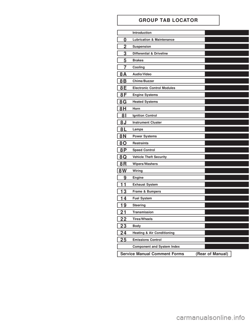
GROUP TAB LOCATOR
Introduction
0Lubrication & Maintenance
2Suspension
3Differential & Driveline
5Brakes
7Cooling
8AAudio/Video
8BChime/Buzzer
8EElectronic Control Modules
8FEngine Systems
8GHeated Systems
8HHorn
8IIgnition Control
8JInstrument Cluster
8LLamps
8NPower Systems
8ORestraints
8PSpeed Control
8QVehicle Theft Security
8RWipers/Washers
8WWiring
9Engine
11Exhaust System
13Frame & Bumpers
14Fuel System
19Steering
21Transmission
22Tires/Wheels
23Body
24Heating & Air Conditioning
25Emissions Control
Component and System Index
Service Manual Comment Forms (Rear of Manual)