2006 MERCEDES-BENZ SPRINTER oil capacities
[x] Cancel search: oil capacitiesPage 716 of 2305
LUBRICATION & MAINTENANCE
TABLE OF CONTENTS
page page
FLUID TYPES
DESCRIPTION
PARTS AND LUBRICANT
RECOMMENDATIONS...................1
AUTOMATIC TRANSMISSION FLUID - NAG1 . 1
AXLE FLUID..........................2
BRAKE FLUID.........................2
HOAT COOLANT.......................2
ENGINE OIL - DIESEL ENGINES...........3
FUEL REQUIREMENTS - DIESEL ENGINE . . . 4
POWER STEERING FLUID...............5
OPERATION - AUTOMATIC TRANSMISSION
FLUID...............................5
FLUID CAPACITIES
SPECIFICATIONS - FLUID CAPACITIES.......5FLUID FILL/CHECK LOCATIONS
INSPECTION - FLUID FILL/CHECK
LOCATIONS..........................5
HOISTING
STANDARD PROCEDURE - HOISTING........5
JUMP STARTING
STANDARD PROCEDURE - JUMP STARTING . . 6
TOWING
STANDARD PROCEDURE - TOWING.........7
MAINTENANCE SCHEDULES
DESCRIPTION..........................8
INTERNATIONAL SYMBOLS
DESCRIPTION..........................9
FLUID TYPES
DESCRIPTION
PARTS AND LUBRICANT RECOMMENDATIONS
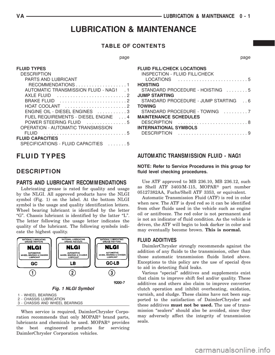
Lubricating grease is rated for quality and usage
by the NLGI. All approved products have the NLGI
symbol (Fig. 1) on the label. At the bottom NLGI
symbol is the usage and quality identification letters.
Wheel bearing lubricant is identified by the letter
ªGº. Chassis lubricant is identified by the latter ªLº.
The letter following the usage letter indicates the
quality of the lubricant. The following symbols indi-
cate the highest quality.
When service is required, DaimlerChrysler Corpo-
ration recommends that only MOPARtbrand parts,
lubricants and chemicals be used. MOPARtprovides
the best engineered products for servicing
DaimlerChrysler Corporation vehicles.
AUTOMATIC TRANSMISSION FLUID - NAG1
NOTE: Refer to Service Procedures in this group for
fluid level checking procedures.
Use ATF approved to MB 236.10, MB 236.12, such
as Shell ATF 3403/M-115, MOPARtpart number
05127382AA, Fuchs/Shell ATF 3353, or equivalent.
Automatic Transmission Fluid (ATF) is red in color
when new. The ATF is dyed red so it can be identified
from other fluids used in the vehicle such as engine
oil or antifreeze. The red color is not permanent and
is not an indicator of fluid condition. As the vehicle is
driven, the ATF will begin to look darker in color and
may eventually become brown.This is normal.
FLUID ADDITIVES
DaimlerChrysler strongly recommends against the
addition of any fluids to the transmission, other than
those automatic transmission fluids listed above.
Exceptions to this policy are the use of special dyes
to aid in detecting fluid leaks.
Various ªspecialº additives and supplements exist
that claim to improve shift feel and/or quality. These
additives and others also claim to improve converter
clutch operation and inhibit overheating, oxidation,
varnish, and sludge. These claims have not been sup-
ported to the satisfaction of DaimlerChrysler and
these additivesmust not be used.The use of trans-
mission ªsealersº should also be avoided, since they
may adversely affect the integrity of transmission
seals.
Fig. 1 NLGI Symbol
1 - WHEEL BEARINGS
2 - CHASSIS LUBRICATION
3 - CHASSIS AND WHEEL BEARINGS
VALUBRICATION & MAINTENANCE 0 - 1
Page 720 of 2305
Do not blend other specific fuel additives with die-
sel fuel. They only result in unnecessary cost, and
may be harmful to the engine operation.
POWER STEERING FLUID
No fluid service required. Filled with Power Steer-
ing Fluid approved to MB 236.3, such as Mobil
ATF-D (Exxon Mobil Corporation) or equivalent.
OPERATION - AUTOMATIC TRANSMISSION
FLUID
The automatic transmission fluid is selected based
upon several qualities. The fluid must provide a high
level of protection for the internal components by
providing a lubricating film between adjacent metal
components. The fluid must also be thermally stable
so that it can maintain a consistent viscosity through
a large temperature range. If the viscosity stays con-
stant through the temperature range of operation,
transmission operation and shift feel will remain con-
sistent. Transmission fluid must also be a good con-
ductor of heat. The fluid must absorb heat from the
internal transmission components and transfer that
heat to the transmission case.
FLUID CAPACITIES
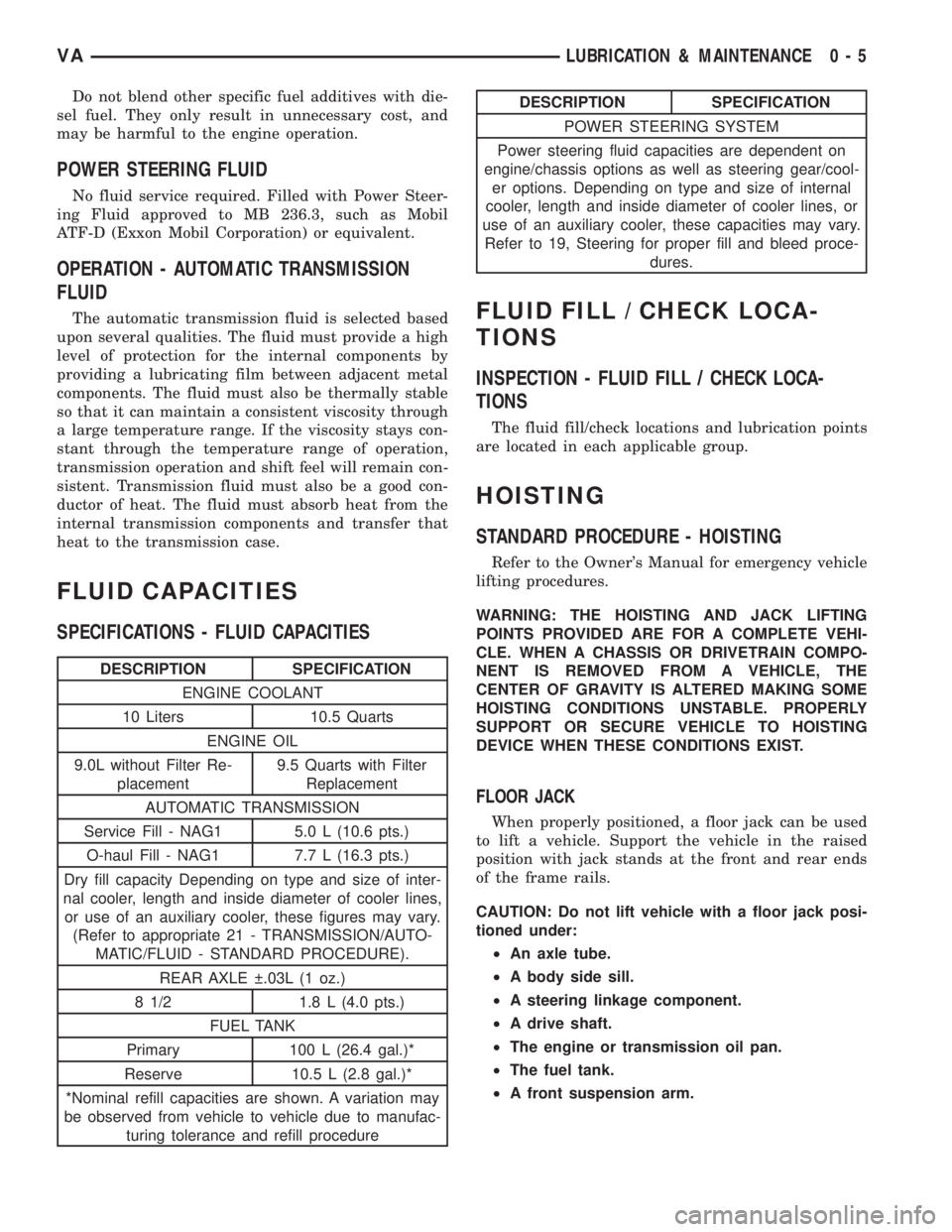
SPECIFICATIONS - FLUID CAPACITIES
DESCRIPTION SPECIFICATION
ENGINE COOLANT
10 Liters 10.5 Quarts
ENGINE OIL
9.0L without Filter Re-
placement9.5 Quarts with Filter
Replacement
AUTOMATIC TRANSMISSION
Service Fill - NAG1 5.0 L (10.6 pts.)
O-haul Fill - NAG1 7.7 L (16.3 pts.)
Dry fill capacity Depending on type and size of inter-
nal cooler, length and inside diameter of cooler lines,
or use of an auxiliary cooler, these figures may vary.
(Refer to appropriate 21 - TRANSMISSION/AUTO-
MATIC/FLUID - STANDARD PROCEDURE).
REAR AXLE .03L (1 oz.)
8 1/2 1.8 L (4.0 pts.)
FUEL TANK
Primary 100 L (26.4 gal.)*
Reserve 10.5 L (2.8 gal.)*
*Nominal refill capacities are shown. A variation may
be observed from vehicle to vehicle due to manufac-
turing tolerance and refill procedure
DESCRIPTION SPECIFICATION
POWER STEERING SYSTEM
Power steering fluid capacities are dependent on
engine/chassis options as well as steering gear/cool-
er options. Depending on type and size of internal
cooler, length and inside diameter of cooler lines, or
use of an auxiliary cooler, these capacities may vary.
Refer to 19, Steering for proper fill and bleed proce-
dures.
FLUID FILL / CHECK LOCA-
TIONS
INSPECTION - FLUID FILL / CHECK LOCA-
TIONS
The fluid fill/check locations and lubrication points
are located in each applicable group.
HOISTING
STANDARD PROCEDURE - HOISTING
Refer to the Owner's Manual for emergency vehicle
lifting procedures.
WARNING: THE HOISTING AND JACK LIFTING
POINTS PROVIDED ARE FOR A COMPLETE VEHI-
CLE. WHEN A CHASSIS OR DRIVETRAIN COMPO-
NENT IS REMOVED FROM A VEHICLE, THE
CENTER OF GRAVITY IS ALTERED MAKING SOME
HOISTING CONDITIONS UNSTABLE. PROPERLY
SUPPORT OR SECURE VEHICLE TO HOISTING
DEVICE WHEN THESE CONDITIONS EXIST.
FLOOR JACK
When properly positioned, a floor jack can be used
to lift a vehicle. Support the vehicle in the raised
position with jack stands at the front and rear ends
of the frame rails.
CAUTION: Do not lift vehicle with a floor jack posi-
tioned under:
²An axle tube.
²A body side sill.
²A steering linkage component.
²A drive shaft.
²The engine or transmission oil pan.
²The fuel tank.
²A front suspension arm.
VALUBRICATION & MAINTENANCE 0 - 5
Page 900 of 2305
INSTALLATION
(1) Raise and support vehicle.
(2) Position starter motor to transmission housing.
(3) Install 2 mounting bolts. Refer to Torque Spec-
ifications.
(4) Lower vehicle.
(5) Connect battery cable and solenoid wiring to
solenoid (2 nuts). Refer to Torque Specifications.
(6) Position wiring harness trough and install
retaining bolt.
(7) Install new nylon tie-wraps to wiring trough.
(8) Connect negative battery cable.
STARTER MOTOR RELAY
DESCRIPTION
The starter relay is an electromechanical device
that switches battery current to the pull-in coil of the
starter solenoid when ignition switch is turned to
Start position. The starter relay is located in the
Fuse/Relay Block. The Fuse/Relay Block is located
under, and to the left side of the drivers seat. See
Fuse/Relay Block cover for relay identification and
location.
The starter relay is an International Standards
Organization (ISO) relay. Relays conforming to ISO
specifications have common physical dimensions, cur-rent capacities, terminal patterns, and terminal func-
tions.
The starter relay cannot be repaired or adjusted
and, if faulty or damaged, it must be replaced.
REMOVAL
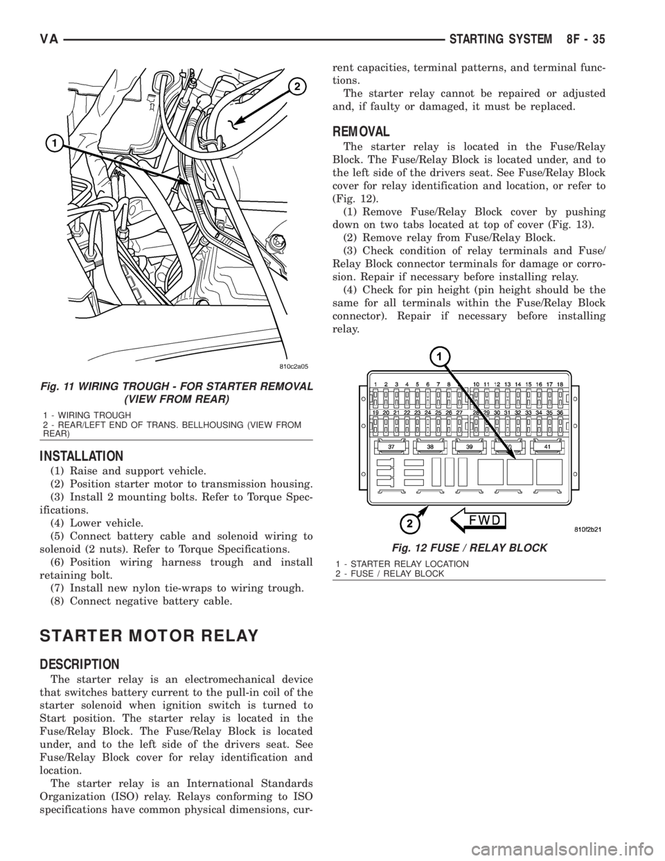
The starter relay is located in the Fuse/Relay
Block. The Fuse/Relay Block is located under, and to
the left side of the drivers seat. See Fuse/Relay Block
cover for relay identification and location, or refer to
(Fig. 12).
(1) Remove Fuse/Relay Block cover by pushing
down on two tabs located at top of cover (Fig. 13).
(2) Remove relay from Fuse/Relay Block.
(3) Check condition of relay terminals and Fuse/
Relay Block connector terminals for damage or corro-
sion. Repair if necessary before installing relay.
(4) Check for pin height (pin height should be the
same for all terminals within the Fuse/Relay Block
connector). Repair if necessary before installing
relay.
Fig. 11 WIRING TROUGH - FOR STARTER REMOVAL
(VIEW FROM REAR)
1 - WIRING TROUGH
2 - REAR/LEFT END OF TRANS. BELLHOUSING (VIEW FROM
REAR)
Fig. 12 FUSE / RELAY BLOCK
1 - STARTER RELAY LOCATION
2 - FUSE / RELAY BLOCK
VASTARTING SYSTEM 8F - 35
Page 904 of 2305
REAR WINDOW DEFOGGER
RELAY
DESCRIPTION
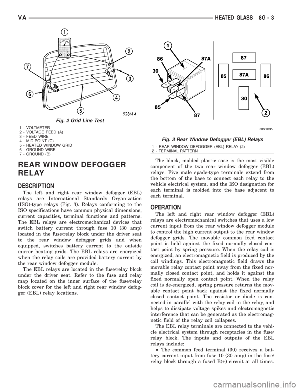
The left and right rear window defogger (EBL)
relays are International Standards Organization
(ISO)-type relays (Fig. 3). Relays conforming to the
ISO specifications have common physical dimensions,
current capacities, terminal functions and patterns.
The EBL relays are electromechanical devices that
switch battery current through fuse 10 (30 amp)
located in the fuse/relay block under the driver seat
to the rear window defogger grids and when
equipped, switches battery current to the outside
mirror heating grids. The EBL relays are energized
when the relay coils are provided battery current by
the rear window defogger module.
The EBL relays are located in the fuse/relay block
under the driver seat. Refer to the fuse and relay
map located on the inner surface of the fuse/relay
block cover for the left and right rear window defog-
ger (EBL) relay locations.The black, molded plastic case is the most visible
component of the two rear window defogger (EBL)
relays. Five male spade-type terminals extend from
the bottom of the base to connect each relay to the
vehicle electrical system, and the ISO designation for
each terminal is molded into the base adjacent to
each terminal.
OPERATION
The left and right rear window defogger (EBL)
relays are electromechanical switches that uses a low
current input from the rear window defogger module
to control the high current output to the rear window
defogger grids. The movable common feed contact
point is held against the fixed normally closed con-
tact point by spring pressure. When the relay coil is
energized, an electromagnetic field is produced by the
coil windings. This electromagnetic field draws the
movable relay contact point away from the fixed nor-
mally closed contact point, and holds it against the
fixed normally open contact point. When the relay
coil is de-energized, spring pressure returns the mov-
able contact point back against the fixed normally
closed contact point. The resistor or diode is con-
nected in parallel with the relay coil in the relay, and
helps to dissipate voltage spikes and electromagnetic
interference that can be generated as the electromag-
netic field of the relay coil collapses.
The EBL relay terminals are connected to the vehi-
cle electrical system through receptacles in the fuse/
relay block. The inputs and outputs of the EBL
relays include:
²The common feed terminal (30) receives a bat-
tery current input from fuse 10 (30 amp) in the fuse/
relay block through a fused B(+) circuit at all times.
Fig. 2 Grid Line Test
1 - VOLTMETER
2 - VOLTAGE FEED (A)
3 - FEED WIRE
4 - MID-POINT (C)
5 - HEATED WINDOW GRID
6 - GROUND WIRE
7 - GROUND (B)
Fig. 3 Rear Window Defogger (EBL) Relays
1 - REAR WINDOW DEFOGGER (EBL) RELAY (2)
2 - TERMINAL PATTERN
VAHEATED GLASS 8G - 3
Page 913 of 2305

(6) Working from the underside of the switch, gen-
tly rock the switch back and forth out of its mounting
location in the switch bezel.
INSTALLATION
(1) Install the heated seat switch in its mounting
location in the switch bezel.
(2) Connect electrical connections.
(3) Position the switch bezel and install the retain-
ing screw. Refer to the Body section for the proce-
dure.
(4) Install the storage bin. Refer to the Body sec-
tion for the procedure.
(5) Install the gear selector bezel trim. Refer to the
Body section for the procedure.
(6) Connect the negative battery cable.
HEATED SEAT ELEMENT
DESCRIPTION
The heated seat system includes two seat heating
elements in each front seat, one for the seat cushion
(Fig. 1) and the other for the seat back. All models
use two resistor wire heating elements for each seat
that are connected in series with the Heated Seat
Relay. The temperature sensor is a Negative Temper-
ature Coefficient (NTC) thermistor. One temperature
sensor is used for each seat, and it is located in the
seat cushion heating element for all models.The seat heating elements are glued onto the seat
and seat back cushions. The heated seat elements
and the temperature sensor cannot be adjusted or
repaired and, if faulty or damaged a new seat assem-
bly must be installed.
OPERATION
The heated seat elements resist the flow of electri-
cal current. When battery current is passed through
the elements, the energy lost by the resistance of the
elements is released in the form of heat. The heated
seat temperature sensor is a NTC thermistor. When
the temperature of the seat cushion cover rises, the
resistance of the sensor decreases. The heated seat
relay uses this temperature sensor input to monitor
the temperature of the seat, and regulates the cur-
rent flow to the seat heating elements accordingly.
DIAGNOSIS AND TESTING - HEATED SEAT
ELEMENT
For complete circuit diagrams, refer toWiring.
NOTE: When checking heated seat elements for
continuity, be certain to move the heating element
being checked. Moving the element, such as sitting
in the seat will eliminate the possibility of an inter-
mittent open in the element which would only be
evident if the element was in a certain position.
Failure to check the element in various positions
could result in an incomplete test.
(1) Disconnect and isolate the battery negative
cable. Disconnect the heated seat element wire har-
ness connector from under the seat cushion. Check
for continuity between the seat heater driver circuit
and ground. There should be continuity, less than 7
ohms. If OK, go to Step 2. If not OK, replace the seat
assembly.
(2) Check for continuity between the seat heater
B+ driver circuit cavity and the seat back frame.
There should benocontinuity. If OK, heating ele-
ment is OK at this time. If not OK, replace the seat
assembly.
HEATED SEAT RELAY
DESCRIPTION
The heated seat relay is an electromechanical
device that switches 12v battery current to the
heated seat elements when the relay control coil is
energized. The heated seat relay is located in the
Fuse Block, under the drivers seat. The heated seat
relay is a International Standards Organization
(ISO) relay. Relays conforming to the ISO specifica-
tions have common physical dimensions, current
capacities, terminal patterns, and terminal functions.
Fig. 1 Heated Seat Element - Typical
1 - Seat Back Wire Harness
2 - Heated Seat Wire Harness Connector
3 - Heated Seat Cushion Element
8G - 12 HEATED SEATSVA
Page 1573 of 2305
repaired and, if faulty or damaged, it must be
replaced.
OPERATION
The power outlet base or receptacle shell is con-
nected to ground, and an insulated contact in the
bottom of the shell is connected to battery current.
The power outlet receives battery voltage from a fuse
in the fuse block at all times.
DIAGNOSIS AND TESTING - POWER OUTLET
(1) Check for battery voltage at the fused B(+) fuse
in the fuse block. If OK, go to Step 2. If not OK,
repair the open fused B(+) circuit to the battery as
required.
(2) Check for continuity between the inside cir-
cumference of the power outlet receptacle and a good
ground. There should be continuity. If OK, go to Step
3. If not OK, go to Step 4.
(3) Check for battery voltage at the insulated con-
tact located at the back of the power outlet recepta-
cle. If not OK, go to Step 4.
(4) Disconnect and isolate the battery negative
cable. Check for continuity between the ground cir-
cuit cavity of the power outlet wire harness connector
and a good ground. There should be continuity. If
OK, go to Step 5. If not OK, repair the open ground
circuit to ground as required.
(5) Connect the battery negative cable. Check for
battery voltage at the fused B(+) circuit cavity of the
power outlet wire harness connector. If OK, replace
the faulty power outlet receptacle. If not OK, repair
the open fused B(+) circuit to the fuse in the fuse
block as required.
REMOVAL
(1) Disconnect and isolate the battery negative
cable.
(2) Pull the cigar lighter knob and element out of
the cigar lighter receptacle base, or unsnap the pro-
tective cap from the power outlet receptacle base.
(3) Look inside the cigar lighter or power outlet
receptacle base and note the position of the rectangu-
lar retaining bosses of the mount that secures the
receptacle base to the instrument panel.
(4) Insert a pair of external snap ring pliers into
the cigar lighter or power outlet receptacle base and
engage the tips of the pliers with the retaining
bosses of the mount.
(5) Squeeze the pliers to disengage the mount
retaining bosses from the receptacle base and, using
a gentle rocking motion, pull the pliers and the
receptacle base out of the mount.
(6) Disconnect the instrument panel wire harness
connector from the connector receptacle of the cigar
lighter or the power outlet receptacle base.(7) Remove the cigar lighter or power outlet mount
from the instrument panel.
INSTALLATION
(1) Install the cigar lighter or power outlet mount
into the instrument panel.
(2) Reconnect the instrument panel wire harness
connector to the connector receptacle of the cigar
lighter or the power outlet receptacle base.
(3) Align the splines on the outside of the cigar
lighter or power outlet receptacle base connector
receptacle with the grooves on the inside of the
mount.
(4) Press firmly on the cigar lighter or power out-
let receptacle base until the retaining bosses of the
mount are fully engaged in their receptacles.
(5) Install the cigar lighter knob and element into
the cigar lighter receptacle base.
(6) Reconnect the battery negative cable.
RELAY
DESCRIPTION
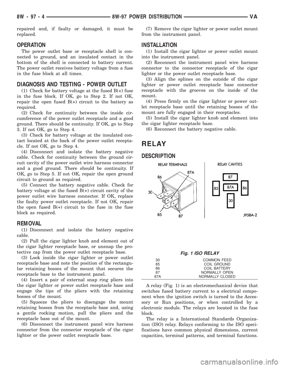
A relay (Fig. 1) is an electromechanical device that
switches fused battery current to a electrical compo-
nent when the ignition switch is turned to the Acces-
sory or Run positions, or when controlled by a
electronic module. The relays are located in the fuse
block.
The relay is a International Standards Organiza-
tion (ISO) relay. Relays conforming to the ISO speci-
fications have common physical dimensions, current
capacities, terminal patterns, and terminal functions.
Fig. 1 ISO RELAY
30 COMMON FEED
85 COIL GROUND
86 COIL BATTERY
87 NORMALLY OPEN
87A NORMALLY CLOSED
8W - 97 - 4 8W-97 POWER DISTRIBUTIONVA
Page 2061 of 2305
CONTROLS - REAR
TABLE OF CONTENTS
page page
A/C CLUTCH RELAY
DESCRIPTION.........................24
OPERATION...........................25
REMOVAL.............................25
INSTALLATION.........................26
A/C CONDENSER FAN RELAY
DESCRIPTION.........................26
OPERATION...........................26
REMOVAL.............................27
INSTALLATION.........................28
A/C CONTROL MODULE
DESCRIPTION.........................28
OPERATION...........................28
REMOVAL.............................29
INSTALLATION.........................30
A/C HIGH PRESSURE SWITCH
DESCRIPTION.........................30
OPERATION...........................30
REMOVAL.............................31
INSTALLATION.........................31
A/C LOW PRESSURE SWITCH
DESCRIPTION.........................32
OPERATION...........................32
REMOVAL.............................32
INSTALLATION.........................33
BLOWER MOTOR RELAY
DESCRIPTION.........................33
OPERATION...........................33
REMOVAL.............................34
INSTALLATION.........................35
BLOWER MOTOR SWITCH
DESCRIPTION.........................35
OPERATION...........................35
DIAGNOSIS AND TESTING
REAR BLOWER MOTOR SWITCH.........36REMOVAL.............................36
INSTALLATION.........................37
EVAPORATOR TEMPERATURE SENSOR
DESCRIPTION.........................37
OPERATION...........................37
REMOVAL.............................37
INSTALLATION.........................38
TEMPERATURE CONTROL
DESCRIPTION.........................38
OPERATION...........................38
DIAGNOSIS AND TESTING
REAR A/C TEMPERATURE CONTROL.....39
REMOVAL.............................39
INSTALLATION.........................40
TEMPERATURE SENSOR
DESCRIPTION.........................40
OPERATION...........................40
DIAGNOSIS AND TESTING
REAR TEMPERATURE SENSOR..........40
REMOVAL.............................40
INSTALLATION.........................41
SUPPRESSOR FILTER - REAR BLOWER
MOTOR
DESCRIPTION.........................41
OPERATION...........................41
REMOVAL.............................42
INSTALLATION.........................43
SUPPRESSOR FILTER - REAR CONDENSER
FA N
DESCRIPTION.........................43
OPERATION...........................44
REMOVAL.............................44
INSTALLATION.........................44
A / C CLUTCH RELAY
DESCRIPTION
The rear A/C clutch relay for the rear A/C system
is an International Standards Organization (ISO)-
type relay (Fig. 1). Relays conforming to the ISO
specifications have common physical dimensions, cur-
rent capacities, terminal functions and patterns. The
rear A/C clutch relay is an electromechanical device
that uses a low current input controlled by the rear
A/C control module to control the high current output
to the A/C clutch field coil for the rear A/C system.The rear A/C clutch relay is located in the relay
block in the rear A/C evaporator housing.
24 - 24 CONTROLS - REARVA
Page 2063 of 2305
INSTALLATION
(1) Position the rear A/C clutch relay into the
proper receptacle of the relay block located in the
rear A/C evaporator housing.
(2) Align the A/C clutch relay terminals with the
terminal cavities in the relay block receptacle and
push down firmly on the relay until the terminals
are fully seated.
(3) Install the rear air filter (Refer to 24 - HEAT-
ING & AIR CONDITIONING/DISTRIBUTION -
REAR/AIR FILTER - INSTALLATION).
(4) Reconnect the negative battery cable.
A / C CONDENSER FAN RELAY
DESCRIPTION
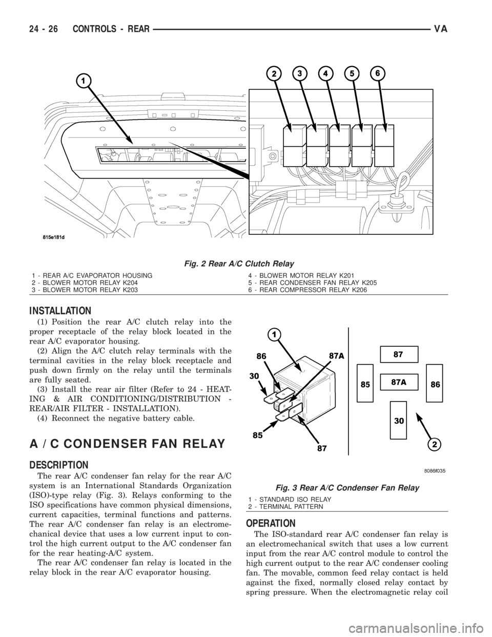
The rear A/C condenser fan relay for the rear A/C
system is an International Standards Organization
(ISO)-type relay (Fig. 3). Relays conforming to the
ISO specifications have common physical dimensions,
current capacities, terminal functions and patterns.
The rear A/C condenser fan relay is an electrome-
chanical device that uses a low current input to con-
trol the high current output to the A/C condenser fan
for the rear heating-A/C system.
The rear A/C condenser fan relay is located in the
relay block in the rear A/C evaporator housing.
OPERATION
The ISO-standard rear A/C condenser fan relay is
an electromechanical switch that uses a low current
input from the rear A/C control module to control the
high current output to the rear A/C condenser cooling
fan. The movable, common feed relay contact is held
against the fixed, normally closed relay contact by
spring pressure. When the electromagnetic relay coil
Fig. 2 Rear A/C Clutch Relay
1 - REAR A/C EVAPORATOR HOUSING
2 - BLOWER MOTOR RELAY K204
3 - BLOWER MOTOR RELAY K2034 - BLOWER MOTOR RELAY K201
5 - REAR CONDENSER FAN RELAY K205
6 - REAR COMPRESSOR RELAY K206
Fig. 3 Rear A/C Condenser Fan Relay
1 - STANDARD ISO RELAY
2 - TERMINAL PATTERN
24 - 26 CONTROLS - REARVA