2006 MERCEDES-BENZ SPRINTER seat adjustment
[x] Cancel search: seat adjustmentPage 805 of 2305
(3) Check the brake system for any leaks.
(4) Reconnect the electrical connector to the brake
fluid level indicator (Fig. 14).
ALB LEVER
REMOVAL
(1) Raise and support the vehicle.
(2) Remove the retaining clip for the ALB lever
(Fig. 15).
(3) Remove the bolt for the lever at the axle (Fig.
15).
(4) Remove the lever.
INSTALLATION
(1) Install the lever to the vehicle.
(2) Install the lower mounting bolt to the axle (Fig.
15).
(3) Install the lever to the shock bolt and then
install the clip (Fig. 15).
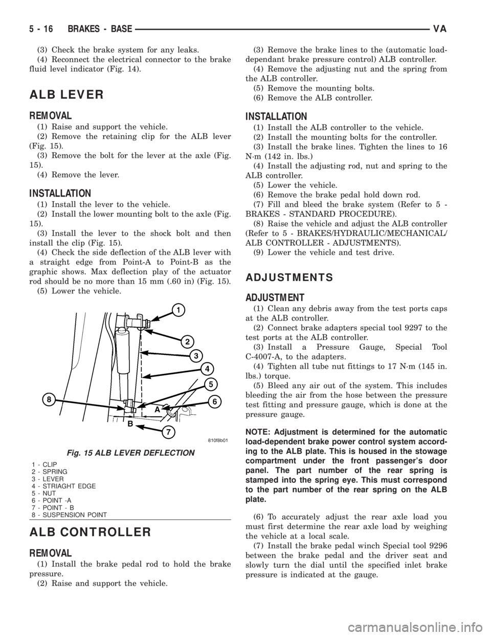
(4) Check the side deflection of the ALB lever with
a straight edge from Point-A to Point-B as the
graphic shows. Max deflection play of the actuator
rod should be no more than 15 mm (.60 in) (Fig. 15).
(5) Lower the vehicle.
ALB CONTROLLER
REMOVAL
(1) Install the brake pedal rod to hold the brake
pressure.
(2) Raise and support the vehicle.(3) Remove the brake lines to the (automatic load-
dependant brake pressure control) ALB controller.
(4) Remove the adjusting nut and the spring from
the ALB controller.
(5) Remove the mounting bolts.
(6) Remove the ALB controller.
INSTALLATION
(1) Install the ALB controller to the vehicle.
(2) Install the mounting bolts for the controller.
(3) Install the brake lines. Tighten the lines to 16
N´m (142 in. lbs.)
(4) Install the adjusting rod, nut and spring to the
ALB controller.
(5) Lower the vehicle.
(6) Remove the brake pedal hold down rod.
(7) Fill and bleed the brake system (Refer to 5 -
BRAKES - STANDARD PROCEDURE).
(8) Raise the vehicle and adjust the ALB controller
(Refer to 5 - BRAKES/HYDRAULIC/MECHANICAL/
ALB CONTROLLER - ADJUSTMENTS).
(9) Lower the vehicle and test drive.
ADJUSTMENTS
ADJUSTMENT
(1) Clean any debris away from the test ports caps
at the ALB controller.
(2) Connect brake adapters special tool 9297 to the
test ports at the ALB controller.
(3) Install a Pressure Gauge, Special Tool
C-4007-A, to the adapters.
(4) Tighten all tube nut fittings to 17 N´m (145 in.
lbs.) torque.
(5) Bleed any air out of the system. This includes
bleeding the air from the hose between the pressure
test fitting and pressure gauge, which is done at the
pressure gauge.
NOTE: Adjustment is determined for the automatic
load-dependent brake power control system accord-
ing to the ALB plate. This is housed in the stowage
compartment under the front passenger's door
panel. The part number of the rear spring is
stamped into the spring eye. This must correspond
to the part number of the rear spring on the ALB
plate.
(6) To accurately adjust the rear axle load you
must first determine the rear axle load by weighing
the vehicle at a local scale.
(7) Install the brake pedal winch Special tool 9296
between the brake pedal and the driver seat and
slowly turn the dial until the specified inlet brake
pressure is indicated at the gauge.
Fig. 15 ALB LEVER DEFLECTION
1 - CLIP
2 - SPRING
3 - LEVER
4 - STRIAGHT EDGE
5 - NUT
6 - POINT -A
7 - POINT - B
8 - SUSPENSION POINT
5 - 16 BRAKES - BASEVA
Page 953 of 2305
seat riser, a fog lamp switch installed in the cluster
bezel on the instrument panel outboard of the steer-
ing column, and a fog lamp bulb installed in each of
the two front lamp units. The front fog lamps have a
path to ground at all times through their connection
to the vehicle wire harness. The headlamp switch cir-
cuitry of the left (lighting) control stalk of the multi-
function switch controls front fog lamp operation by
providing battery current to the front fog lamp relay
only when the low beam headlamps are selected. The
fog lamp switch controls front fog lamp operation by
energizing or de-energizing the front fog lamp relay
control coil.
HAZARD WARNING LAMPS
With the hazard switch in the On position, the
hazard switch button illuminates and the right and
left turn signal indicators as well as the right and
left turn signal lamps begin to flash on and off. When
the hazard warning system is activated, the hazard
switch circuitry within the multi-function switch and
the wipers, turn signals and engine start control
module electronic circuitry within the fuse block will
repeatedly energize and de-energize the turn signal
relay located in the fuse block. The turn signal relay
switches battery current from a fused B(+) fuse in
the fuse block to the turn signal indicators and the
turn signal lamps. The flashing of the hazard switch
button illumination lamp is also controlled by the
output from the turn signal relay.
HEADLAMPS
The headlamp system includes the exterior lighting
switches integral to the left (lighting) control stalk of
the multi-function switch as well as the low and high
beam bulbs installed in the right and left front lamp
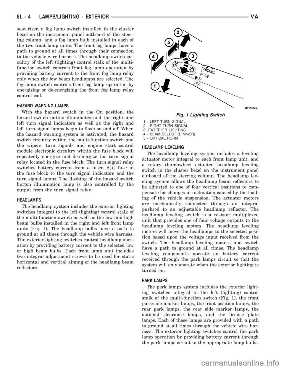
units (Fig. 1). The headlamp bulbs have a path to
ground at all times through the vehicle wire harness.
The exterior lighting switches control headlamp oper-
ation by providing battery current to the selected low
or high beam bulbs. Each front lamp unit includes
two integral adjustment screws to be used for static
horizontal and vertical aiming of the headlamp beam
reflectors.HEADLAMP LEVELING
The headlamp leveling system includes a leveling
actuator motor integral to each front lamp unit, and
a rotary thumbwheel actuated headlamp leveling
switch in the cluster bezel on the instrument panel
outboard of the steering column. The headlamp lev-
eling system allows the headlamp beam reflectors to
be adjusted to one of four vertical positions to com-
pensate for changes in inclination caused by the load-
ing of the vehicle suspension. The actuator motors
are mechanically connected through an integral
pushrod to an adjustable headlamp reflector. The
headlamp leveling switch is a resistor multiplexed
unit that provides one of four voltage outputs to the
headlamp leveling motors. The headlamp leveling
motors will move the headlamps to the selected posi-
tion based upon the voltage input received from the
switch. The headlamp leveling motors and switch
have a path to ground at all times. The headlamp
leveling components operate on battery current
received through the park lamps circuit so that the
system will only operate when the exterior lighting is
turned on.
PARK LAMPS
The park lamps system includes the exterior light-
ing switches integral to the left (lighting) control
stalk of the multi-function switch (Fig. 1), the front
park/side marker lamps, the front position lamps, the
rear park lamps, the rear side marker lamps, the
optional clearance lamps, and the license plate
lamps. Each of these lamps are provided with a path
to ground at all times through the vehicle wire har-
ness. The exterior lighting switches control the park
lamp operation by providing battery current through
the park lamps circuit to the appropriate lamp bulbs.
Fig. 1 Lighting Switch
1 - LEFT TURN SIGNAL
2 - RIGHT TURN SIGNAL
3 -EXTERIOR LIGHTING
4 - BEAM SELECT (DIMMER)
5 - OPTICAL HORN
8L - 4 LAMPS/LIGHTING - EXTERIORVA
Page 956 of 2305
INSTALLATION
WARNING: To avoid personal injury or death, on
vehicles equipped with airbags, disable the supple-
mental restraint system before attempting any
steering wheel, steering column, airbag, seat belt
tensioner, or instrument panel component diagno-
sis or service. Disconnect and isolate the battery
negative (ground) cable, then wait two minutes for
the system capacitor to discharge before perform-
ing further diagnosis or service. This is the only
sure way to disable the supplemental restraint sys-
tem. Failure to take the proper precautions could
result in accidental airbag deployment.
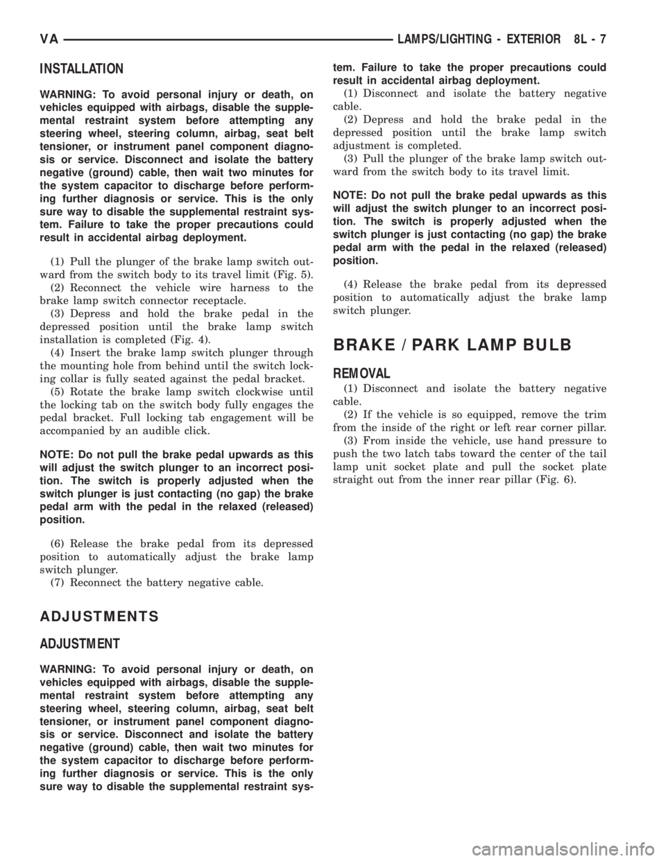
(1) Pull the plunger of the brake lamp switch out-
ward from the switch body to its travel limit (Fig. 5).
(2) Reconnect the vehicle wire harness to the
brake lamp switch connector receptacle.
(3) Depress and hold the brake pedal in the
depressed position until the brake lamp switch
installation is completed (Fig. 4).
(4) Insert the brake lamp switch plunger through
the mounting hole from behind until the switch lock-
ing collar is fully seated against the pedal bracket.
(5) Rotate the brake lamp switch clockwise until
the locking tab on the switch body fully engages the
pedal bracket. Full locking tab engagement will be
accompanied by an audible click.
NOTE: Do not pull the brake pedal upwards as this
will adjust the switch plunger to an incorrect posi-
tion. The switch is properly adjusted when the
switch plunger is just contacting (no gap) the brake
pedal arm with the pedal in the relaxed (released)
position.
(6) Release the brake pedal from its depressed
position to automatically adjust the brake lamp
switch plunger.
(7) Reconnect the battery negative cable.
ADJUSTMENTS
ADJUSTMENT
WARNING: To avoid personal injury or death, on
vehicles equipped with airbags, disable the supple-
mental restraint system before attempting any
steering wheel, steering column, airbag, seat belt
tensioner, or instrument panel component diagno-
sis or service. Disconnect and isolate the battery
negative (ground) cable, then wait two minutes for
the system capacitor to discharge before perform-
ing further diagnosis or service. This is the only
sure way to disable the supplemental restraint sys-tem. Failure to take the proper precautions could
result in accidental airbag deployment.
(1) Disconnect and isolate the battery negative
cable.
(2) Depress and hold the brake pedal in the
depressed position until the brake lamp switch
adjustment is completed.
(3) Pull the plunger of the brake lamp switch out-
ward from the switch body to its travel limit.
NOTE: Do not pull the brake pedal upwards as this
will adjust the switch plunger to an incorrect posi-
tion. The switch is properly adjusted when the
switch plunger is just contacting (no gap) the brake
pedal arm with the pedal in the relaxed (released)
position.
(4) Release the brake pedal from its depressed
position to automatically adjust the brake lamp
switch plunger.
BRAKE / PARK LAMP BULB
REMOVAL
(1) Disconnect and isolate the battery negative
cable.
(2) If the vehicle is so equipped, remove the trim
from the inside of the right or left rear corner pillar.
(3) From inside the vehicle, use hand pressure to
push the two latch tabs toward the center of the tail
lamp unit socket plate and pull the socket plate
straight out from the inner rear pillar (Fig. 6).
VALAMPS/LIGHTING - EXTERIOR 8L - 7
Page 963 of 2305
ADJUSTMENTS
ADJUSTMENT - FRONT LAMP UNIT
VEHICLE PREPARATION FOR FRONT LAMP UNIT
ALIGNMENT
(1) Verify headlamp dimmer (multi-function)
switch, fog lamp switch (if equipped), and high beam
indicator operation.
(2) Verify that the headlamp leveling switch is in
the ª0º position.
(3) Repair or replace any faulty or damaged com-
ponents that could interfere with proper lamp align-
ment.
(4) Verify proper tire inflation.
(5) Clean front lamp unit lenses.
(6) Verify that the cargo compartment is not
heavily loaded. Vehicle should be at or near curb
weight.
(7) The fuel tank should be ªFull.º Add 2.94 kilo-
grams (6.5 pounds) of weight over the fuel tank for
each estimated gallon of missing fuel.
(8) Load the driver's seat with 75 kilograms (165
pounds) of weight.
FRONT LAMP UNIT ALIGNMENT
(1) Position the vehicle on a level surface.
(2) Turn On the headlamp low beams or the fog
lamps (if equipped).
(3) Open the hood.
(4) Set up the headlamp adjuster according to the
instructions provided by the manufacturer of the
unit.
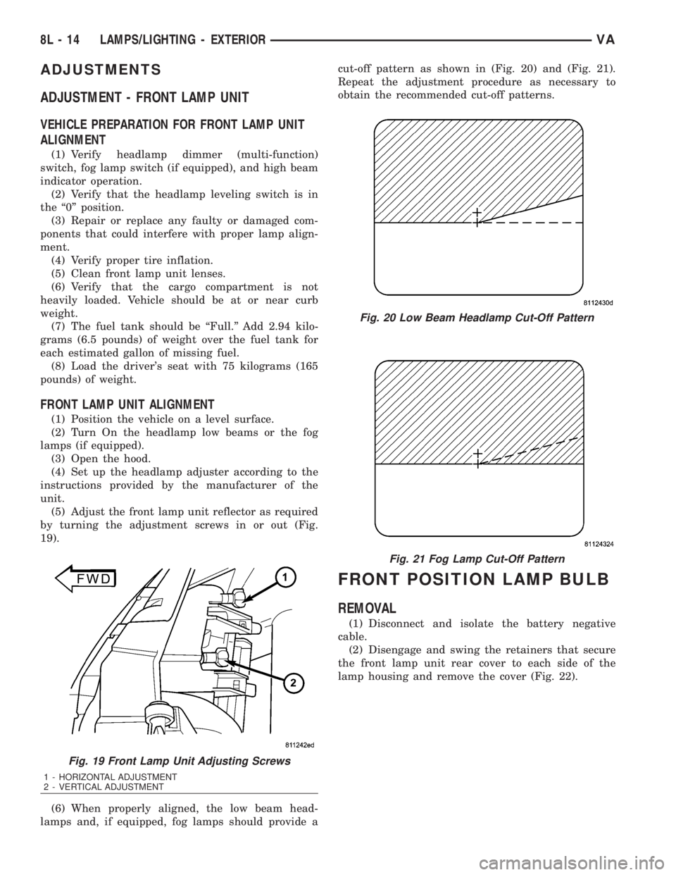
(5) Adjust the front lamp unit reflector as required
by turning the adjustment screws in or out (Fig.
19).
(6) When properly aligned, the low beam head-
lamps and, if equipped, fog lamps should provide acut-off pattern as shown in (Fig. 20) and (Fig. 21).
Repeat the adjustment procedure as necessary to
obtain the recommended cut-off patterns.
FRONT POSITION LAMP BULB
REMOVAL
(1) Disconnect and isolate the battery negative
cable.
(2) Disengage and swing the retainers that secure
the front lamp unit rear cover to each side of the
lamp housing and remove the cover (Fig. 22).
Fig. 19 Front Lamp Unit Adjusting Screws
1 - HORIZONTAL ADJUSTMENT
2 - VERTICAL ADJUSTMENT
Fig. 20 Low Beam Headlamp Cut-Off Pattern
Fig. 21 Fog Lamp Cut-Off Pattern
8L - 14 LAMPS/LIGHTING - EXTERIORVA
Page 1944 of 2305
BODY
TABLE OF CONTENTS
page page
BODY
WARNING
SAFETY PRECAUTIONS AND WARNINGS . . . 1
DIAGNOSIS AND TESTING
DIAGNOSIS AND TESTING - WATER LEAKS . 1
DIAGNOSIS AND TESTING - WIND NOISE . . . 2
STANDARD PROCEDURE
STANDARD PROCEDURE - PLASTIC BODY
PANEL REPAIR........................3
STANDARD PROCEDURE - BUZZ, SQUEAK
& RATTLE...........................10
SPECIFICATIONS.......................11DOOR - FRONT..........................13
DOORS - REAR..........................23
DOORS - SLIDING........................35
EXTERIOR..............................48
HOOD.................................51
INSTRUMENT PANEL.....................55
INTERIOR..............................70
PAINT.................................77
SEATS.................................79
STATIONARY GLASS.....................84
WEATHERSTRIP/SEALS...................90
BODY STRUCTURE.......................91
BODY
WARNING
SAFETY PRECAUTIONS AND WARNINGS
WARNING: USE AN OSHA APPROVED BREATHING
FILTER WHEN SPRAYING PAINT OR SOLVENTS IN
A CONFINED AREA. PERSONAL INJURY CAN
RESULT.
²AVOID PROLONGED SKIN CONTACT WITH
PETROLEUM OR ALCOHOL ± BASED CLEANING
SOLVENTS. PERSONAL INJURY CAN RESULT.
²DO NOT STAND UNDER A HOISTED VEHICLE
THAT IS NOT PROPERLY SUPPORTED ON SAFETY
STANDS. PERSONAL INJURY CAN RESULT.
CAUTION: When holes must be drilled or punched
in an inner body panel, verify depth of space to the
outer body panel, electrical wiring, or other compo-
nents. Damage to vehicle can result.
²Do not weld exterior panels unless combustible
material on the interior of vehicle is removed from
the repair area. Fire or hazardous conditions, can
result.
²Always have a fire extinguisher ready for use
when welding.
²Disconnect the negative (-) cable clamp from
the battery when servicing electrical components
that are live when the ignition is OFF. Damage to
electrical system can result.
²Do not use abrasive chemicals or compounds
on painted surfaces. Damage to finish can result.²Do not use harsh alkaline based cleaning sol-
vents on painted or upholstered surfaces. Damage
to finish or color can result.
²Do not hammer or pound on plastic trim panel
when servicing interior trim. Plastic panels can
break.DIAGNOSIS AND TESTING
DIAGNOSIS AND TESTING - WATER LEAKS
Water leaks can be caused by poor sealing,
improper body component alignment, body seam
porosity, missing plugs, or blocked drain holes. Cen-
trifugal and gravitational force can cause water to
drip from a location away from the actual leak point,
making leak detection difficult. All body sealing
points should be water tight in normal wet-driving
conditions. Water flowing downward from the front of
the vehicle should not enter the passenger or luggage
compartment. Moving sealing surfaces will not
always seal water tight under all conditions. At
times, side glass or door seals will allow water to
enter the passenger compartment during high pres-
sure washing or hard driving rain (severe) condi-
tions. Overcompensating on door or glass
adjustments to stop a water leak that occurs under
severe conditions can cause premature seal wear and
excessive closing or latching effort. After completing
a repair, water test vehicle to verify leak has stopped
before returning vehicle to use.
VISUAL INSPECTION BEFORE WATER LEAK TESTS
Verify that floor and body plugs are in place, body
drains are clear, and body components are properly
VABODY 23 - 1
Page 1973 of 2305
CAUTION: Since the rear doors are components
with static functions it is very important that they
are fastened while driving. This prevents excessive
torsion of the vehicle and leaky rear doors. The rear
doors are fastened by adjusting the closing
wedges.
(9) Closing wedges at bottom must be resting free
of play on plastic closing plates when rear doors are
closed. To adjust, loosen door hinges and raise or
lower complete doors.
(10) Loosen upper closing wedge screws and move
top closing wedge up against plastic closing plate free
of play with rear door closed and tighten screws to 10
N´m (89 in. lbs.).
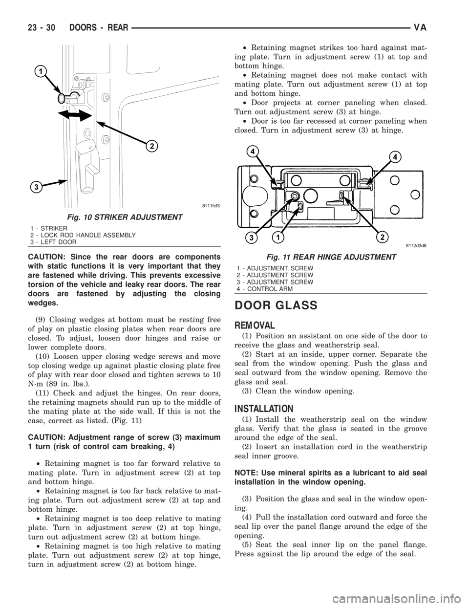
(11) Check and adjust the hinges. On rear doors,
the retaining magnets should run up to the middle of
the mating plate at the side wall. If this is not the
case, correct as listed. (Fig. 11)
CAUTION: Adjustment range of screw (3) maximum
1 turn (risk of control cam breaking, 4)
²Retaining magnet is too far forward relative to
mating plate. Turn in adjustment screw (2) at top
and bottom hinge.
²Retaining magnet is too far back relative to mat-
ing plate. Turn out adjustment screw (2) at top and
bottom hinge.
²Retaining magnet is too deep relative to mating
plate. Turn in adjustment screw (2) at top hinge,
turn out adjustment screw (2) at bottom hinge.
²Retaining magnet is too high relative to mating
plate. Turn out adjustment screw (2) at top hinge,
turn in adjustment screw (2) at bottom hinge.²Retaining magnet strikes too hard against mat-
ing plate. Turn in adjustment screw (1) at top and
bottom hinge.
²Retaining magnet does not make contact with
mating plate. Turn out adjustment screw (1) at top
and bottom hinge.
²Door projects at corner paneling when closed.
Turn out adjustment screw (3) at hinge.
²Door is too far recessed at corner paneling when
closed. Turn in adjustment screw (3) at hinge.
DOOR GLASS
REMOVAL
(1) Position an assistant on one side of the door to
receive the glass and weatherstrip seal.
(2) Start at an inside, upper corner. Separate the
seal from the window opening. Push the glass and
seal outward from the window opening. Remove the
glass and seal.
(3) Clean the window opening.
INSTALLATION
(1) Install the weatherstrip seal on the window
glass. Verify that the glass is seated in the groove
around the edge of the seal.
(2) Insert an installation cord in the weatherstrip
seal inner groove.
NOTE: Use mineral spirits as a lubricant to aid seal
installation in the window opening.
(3) Position the glass and seal in the window open-
ing.
(4) Pull the installation cord outward and force the
seal lip over the panel flange around the edge of the
opening.
(5) Seat the seal inner lip on the panel flange.
Press against the lip around the edge of the seal.
Fig. 10 STRIKER ADJUSTMENT
1 - STRIKER
2 - LOCK ROD HANDLE ASSEMBLY
3 - LEFT DOOR
Fig. 11 REAR HINGE ADJUSTMENT
1 - ADJUSTMENT SCREW
2 - ADJUSTMENT SCREW
3 - ADJUSTMENT SCREW
4 - CONTROL ARM
23 - 30 DOORS - REARVA
Page 1989 of 2305
(3) Install wedge and install screws.
(4) Close sliding door to adjust closing wedge.
(5) Open door and tighten screws to 10 N´m (89 in.
lbs.).
TRIM PANEL
REMOVAL
Upper
(1) Remove rivets and remove panel.
Lower
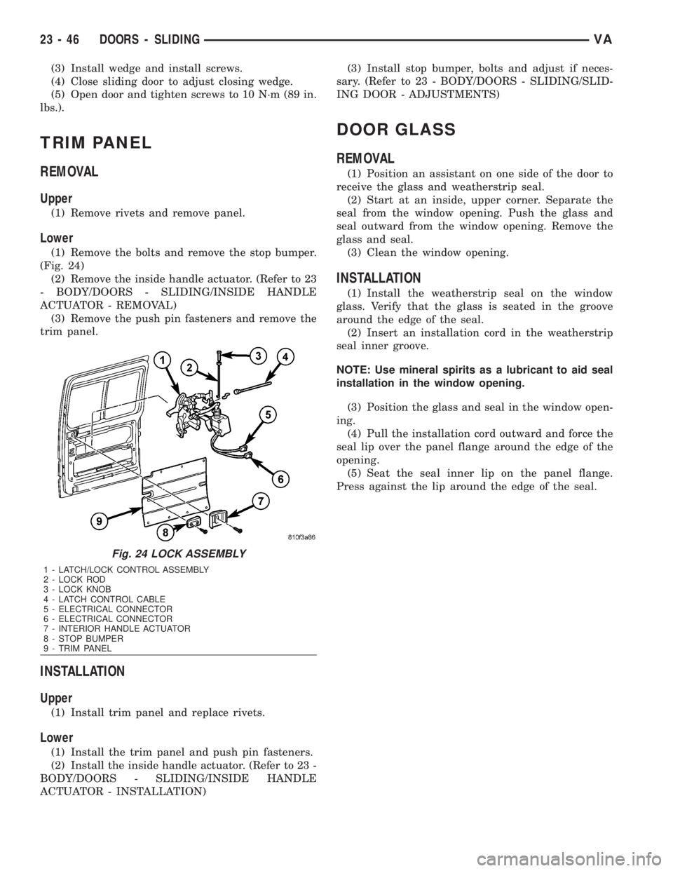
(1) Remove the bolts and remove the stop bumper.
(Fig. 24)
(2) Remove the inside handle actuator. (Refer to 23
- BODY/DOORS - SLIDING/INSIDE HANDLE
ACTUATOR - REMOVAL)
(3) Remove the push pin fasteners and remove the
trim panel.
INSTALLATION
Upper
(1) Install trim panel and replace rivets.
Lower
(1) Install the trim panel and push pin fasteners.
(2) Install the inside handle actuator. (Refer to 23 -
BODY/DOORS - SLIDING/INSIDE HANDLE
ACTUATOR - INSTALLATION)(3) Install stop bumper, bolts and adjust if neces-
sary. (Refer to 23 - BODY/DOORS - SLIDING/SLID-
ING DOOR - ADJUSTMENTS)
DOOR GLASS
REMOVAL
(1) Position an assistant on one side of the door to
receive the glass and weatherstrip seal.
(2) Start at an inside, upper corner. Separate the
seal from the window opening. Push the glass and
seal outward from the window opening. Remove the
glass and seal.
(3) Clean the window opening.
INSTALLATION
(1) Install the weatherstrip seal on the window
glass. Verify that the glass is seated in the groove
around the edge of the seal.
(2) Insert an installation cord in the weatherstrip
seal inner groove.
NOTE: Use mineral spirits as a lubricant to aid seal
installation in the window opening.
(3) Position the glass and seal in the window open-
ing.
(4) Pull the installation cord outward and force the
seal lip over the panel flange around the edge of the
opening.
(5) Seat the seal inner lip on the panel flange.
Press against the lip around the edge of the seal.
Fig. 24 LOCK ASSEMBLY
1 - LATCH/LOCK CONTROL ASSEMBLY
2 - LOCK ROD
3 - LOCK KNOB
4 - LATCH CONTROL CABLE
5 - ELECTRICAL CONNECTOR
6 - ELECTRICAL CONNECTOR
7 - INTERIOR HANDLE ACTUATOR
8 - STOP BUMPER
9 - TRIM PANEL
23 - 46 DOORS - SLIDINGVA
Page 2050 of 2305
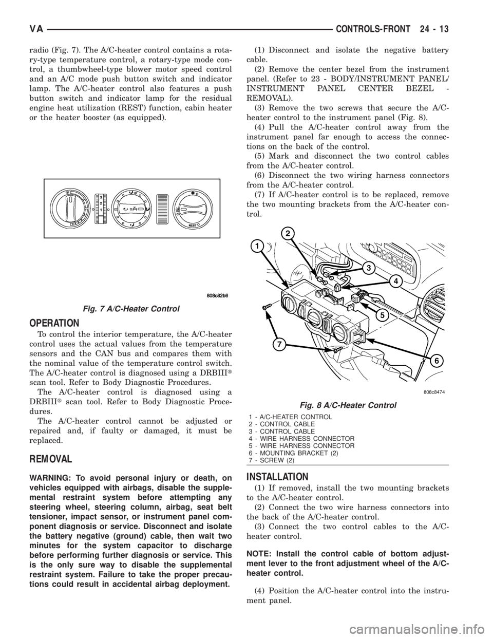
radio (Fig. 7). The A/C-heater control contains a rota-
ry-type temperature control, a rotary-type mode con-
trol, a thumbwheel-type blower motor speed control
and an A/C mode push button switch and indicator
lamp. The A/C-heater control also features a push
button switch and indicator lamp for the residual
engine heat utilization (REST) function, cabin heater
or the heater booster (as equipped).
OPERATION
To control the interior temperature, the A/C-heater
control uses the actual values from the temperature
sensors and the CAN bus and compares them with
the nominal value of the temperature control switch.
The A/C-heater control is diagnosed using a DRBIIIt
scan tool. Refer to Body Diagnostic Procedures.
The A/C-heater control is diagnosed using a
DRBIIItscan tool. Refer to Body Diagnostic Proce-
dures.
The A/C-heater control cannot be adjusted or
repaired and, if faulty or damaged, it must be
replaced.
REMOVAL
WARNING: To avoid personal injury or death, on
vehicles equipped with airbags, disable the supple-
mental restraint system before attempting any
steering wheel, steering column, airbag, seat belt
tensioner, impact sensor, or instrument panel com-
ponent diagnosis or service. Disconnect and isolate
the battery negative (ground) cable, then wait two
minutes for the system capacitor to discharge
before performing further diagnosis or service. This
is the only sure way to disable the supplemental
restraint system. Failure to take the proper precau-
tions could result in accidental airbag deployment.(1) Disconnect and isolate the negative battery
cable.
(2) Remove the center bezel from the instrument
panel. (Refer to 23 - BODY/INSTRUMENT PANEL/
INSTRUMENT PANEL CENTER BEZEL -
REMOVAL).
(3) Remove the two screws that secure the A/C-
heater control to the instrument panel (Fig. 8).
(4) Pull the A/C-heater control away from the
instrument panel far enough to access the connec-
tions on the back of the control.
(5) Mark and disconnect the two control cables
from the A/C-heater control.
(6) Disconnect the two wiring harness connectors
from the A/C-heater control.
(7) If A/C-heater control is to be replaced, remove
the two mounting brackets from the A/C-heater con-
trol.INSTALLATION
(1) If removed, install the two mounting brackets
to the A/C-heater control.
(2) Connect the two wire harness connectors into
the back of the A/C-heater control.
(3) Connect the two control cables to the A/C-
heater control.
NOTE: Install the control cable of bottom adjust-
ment lever to the front adjustment wheel of the A/C-
heater control.
(4) Position the A/C-heater control into the instru-
ment panel.
Fig. 7 A/C-Heater Control
Fig. 8 A/C-Heater Control
1 - A/C-HEATER CONTROL
2 - CONTROL CABLE
3 - CONTROL CABLE
4 - WIRE HARNESS CONNECTOR
5 - WIRE HARNESS CONNECTOR
6 - MOUNTING BRACKET (2)
7 - SCREW (2)
VACONTROLS-FRONT 24 - 13